Transmission tower
 A transmission tower | |
| Type | structure, lattice tower and overhead power line |
|---|---|
| First production | 20th century |
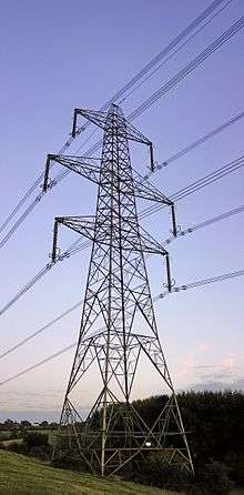
A transmission tower or power tower (electricity pylon in the United Kingdom, Canada and parts of Europe) is a tall structure, usually a steel lattice tower, used to support an overhead power line.
They are used in high-voltage AC and DC systems, and come in a wide variety of shapes and sizes. Typical height ranges from 15 to 55 m (49 to 180 ft),[1] though the tallest are the 370 m (1,214 ft) towers of a 2,700 m (8,858 ft) span of Zhoushan Island Overhead Powerline Tie. In addition to steel, other materials may be used, including concrete and wood.
There are four major categories of transmission towers:[1] suspension, terminal, tension, and transposition. Some transmission towers combine these basic functions. Transmission towers and their overhead power lines are often considered to be a form of visual pollution. Methods to reduce the visual effect include undergrounding.
Naming
"Transmission tower" is the name for the structure used in the industry in the United States, and some other English-speaking countries. The term "pylon" comes from the basic shape of the structure, an obelisk-like structure which tapers toward the top, and the name is mostly used in the United Kingdom and parts of Europe in everyday colloquial speech. This term is used infrequently in the United States, as the word "pylon" is commonly used for many other things, mostly for traffic cones.
High voltage AC transmission towers
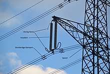
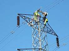
Three-phase electric power systems are used for high voltage (66- or 69-kV and above) and extra-high voltage (110- or 115-kV and above; most often 138- or 230-kV and above in contemporary systems) AC transmission lines. The towers must be designed to carry three (or multiples of three) conductors. The towers are usually steel lattices or trusses (wooden structures are used in Canada, Germany, and Scandinavia in some cases) and the insulators are either glass or porcelain discs or composite insulators using silicone rubber or EPDM rubber material assembled in strings or long rods whose lengths are dependent on the line voltage and environmental conditions.
Typically, one or two ground wires, also called "guard" wires, are placed on top to intercept lightning and harmlessly divert it to ground.
Towers for high- and extra-high voltage are usually designed to carry two or more electric circuits (with very rare exceptions, only one circuit for 500-kV and higher). If a line is constructed using towers designed to carry several circuits, it is not necessary to install all the circuits at the time of construction. Indeed, for economic reasons, some transmission lines are designed for three (or four) circuits, but only two (or three) circuits are initially installed.
Some high voltage circuits are often erected on the same tower as 110 kV lines. Paralleling circuits of 380 kV, 220 kV and 110 kV-lines on the same towers is common. Sometimes, especially with 110 kV circuits, a parallel circuit carries traction lines for railway electrification.
High voltage DC transmission towers
High-voltage direct current (HVDC) transmission lines are either monopolar or bipolar systems. With bipolar systems, a conductor arrangement with one conductor on each side of the tower is used. On some schemes, the ground conductor is used as electrode line or ground return. In this case, it had to be installed with insulators equipped with surge arrestors on the pylons in order to prevent electrochemical corrosion of the pylons. For single-pole HVDC transmission with ground return, towers with only one conductor can be used. In many cases, however, the towers are designed for later conversion to a two-pole system. In these cases, often conductors on both sides of the tower are installed for mechanical reasons. Until the second pole is needed, it is either used as electrode line or joined in parallel with the pole in use. In the latter case, the line from the converter station to the earthing (grounding) electrode is built as underground cable, as overhead line on a separate right of way or by using the ground conductors.
Electrode line towers are used in some HVDC schemes to carry the power line from the converter station to the grounding electrode. They are similar to structures used for lines with voltages of 10–30 kV, but normally carry only one or two conductors.
Railway traction line towers

Towers used for single-phase AC railway traction lines are similar in construction to those towers used for 110 kV three-phase lines. Steel tube or concrete poles are also often used for these lines. However, railway traction current systems are two-pole AC systems, so traction lines are designed for two conductors (or multiples of two, usually four, eight, or twelve). As a rule, the towers of railway traction lines carry two electric circuits, so they have four conductors. These are usually arranged on one level, whereby each circuit occupies one half of the cross arm. For four traction circuits, the arrangement of the conductors is in two-levels and for six electric circuits, the arrangement of the conductors is in three levels.
Towers for different types of currents
AC circuits of different frequency and phase-count, or AC and DC circuits, may be installed on the same tower. Usually all circuits of such lines have voltages of 50 kV and more. However, there are some lines of this type for lower voltages. For example, towers used by both railway traction power circuits and the general three-phase AC grid.
Two very short sections of line carry both AC and DC power circuits. One set of such towers is near the terminal of HVDC Volgograd-Donbass on Volga Hydroelectric Power Station. The other are two towers south of Stenkullen, which carry one circuit of HVDC Konti-Skan and üne circuit of the three-phase AC line Stenkullen-Holmbakullen.
Towers carrying AC circuits and DC electrode lines exist in a section of the powerline between Adalph Static Inverter Plant and Brookston the pylons carry the electrode line of HVDC Square Butte.
The electrode line of HVDC CU at the converter station at Coal Creek Station uses on a short section the towers of two AC lines as support.
The overhead section of the electrode line of Pacific DC Intertie from Sylmar Converter Station to the grounding electrode in the Pacific Ocean near Will Rogers State Beach is also installed on AC pylons. It runs from Sylmar East Converter Station to Southern California Edison Malibu Substation, where the overhead line section ends.
In Germany, Austria and Switzerland some transmission towers carry both public AC grid circuits and railway traction power in order to better use rights of way.
Tower designs
Shape
Different shapes of Transmission towers are typical for different countries. The Shape also depends on voltage and number of circuits.
One circuit
Delta pylons are the most common design for single circuit lines, because of their stability. They have a V-shaped body with a horizontal arm on the top, which forms an inverted Delta. Larger Delta Towers usually use two guard cables.
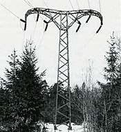
Portal pylons are widely used in Ireland, Scandianvia and Canada. They stand on two legs with one cross arm, which gaves them a H-shape. Up to 110 kV they often were made from wood, but higher voltage lines use steel pylons.
Smaller single circuit pylons may have two small cross arms on one side and one on the other.
Two circuits
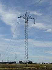
One level pylons only have one cross arm carrying 3 cables on each side. Sometimes they have an additional cross arm for the protection cables. They are frequently used close to airports due to their reduced size.

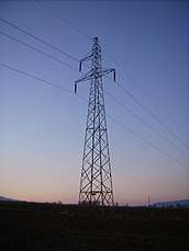
Danube pylons or Donaumasten got their name from a line built in 1927 next to the Danube river. They are the most common design in central european countries like Germany or Poland. They have two cross arms, the upper arm carries one and the lower arm carries two cables on each side. Sometimes they have an additional cross arm for the protection cables.
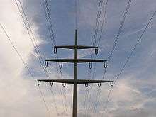
Ton shaped towers are the most common design, they have 3 horizontal levels with one cable very close to the pylon on each side. In the United Kingdom the second level is wider than the other ones while in the United States all cross arms have the same width.
Four circuits
Christmas-tree-shaped towers for 4 or even 6 circuits are common in Germany and have 3 cross arms where the highest arm has each one cable, the second has two cables and the third has three cables on each side. The cables on the third arm usually carry circuits for lower high voltage.
Support structures
.jpg)
Towers may be self-supporting and capable of resisting all forces due to conductor loads, unbalanced conductors, wind and ice in any direction. Such towers often have approximately square bases and usually four points of contact with the ground.
A semi-flexible tower is designed so that it can use overhead grounding wires to transfer mechanical load to adjacent structures, if a phase conductor breaks and the structure is subject to unbalanced loads. This type is useful at extra-high voltages, where phase conductors are bundled (two or more wires per phase). It is unlikely for all of them to break at once, barring a catastrophic crash or storm.
A guyed mast has a very small footprint and relies on guy wires in tension to support the structure and any unbalanced tension load from the conductors. A guyed tower can be made in a V shape, which saves weight and cost.[2]
Materials
Tubular steel
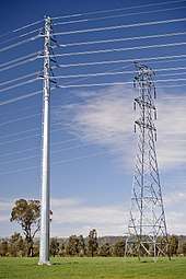
Poles made of tubular steel generally are assembled at the factory and placed on the right-of-way afterward. Because of its durability and ease of manufacturing and installation, many utilities in recent years prefer the use of monopolar steel or concrete towers over lattice steel for new power lines and tower replacements.
In Germany steel tube pylons are also established predominantly for medium voltage lines, in addition, for high voltage transmission lines or two electric circuits for operating voltages by up to 110 kV. Steel tube pylons are also frequently used for 380 kV lines in France, and for 500 kV lines in the United States.
Lattice
A lattice tower is a framework construction made of steel or aluminium sections. Lattice towers are used for power lines of all voltages, and are the most common type for high-voltage transmission lines. Lattice towers are usually made of galvanized steel. Aluminium is used for reduced weight, such as in mountainous areas where structures are placed by helicopter. Aluminium is also used in environments that would be corrosive to steel. The extra material cost of aluminium towers will be offset by lower installation cost. Design of aluminium lattice towers is similar to that for steel, but must take into account aluminium's lower Young's modulus.
A lattice tower is usually assembled at the location where it is to be erected. This makes very tall towers possible, up to 100 m (328 ft) (and in special cases even higher, as in the Elbe crossing 1 and Elbe crossing 2). Assembly of lattice steel towers can be done using a crane. Lattice steel towers are generally made of angle-profiled steel beams (L- or T-beams). For very tall towers, trusses are often used.
Wood
Wood is a material which is limited in use in high-voltage transmission. Because of the limited height of available trees, the maximum height of wooden pylons is limited to approximately 30 m (98 ft). Wood is rarely used for lattice framework. Instead, they are used to build multi-pole structures, such as H-frame and K-frame structures. The voltages they carry are also limited, such as in other regions, where wood structures only carry voltages up to approximately 30 kV.
In countries such as Canada or the United States, wooden towers carry voltages up to 345 kV; these can be less costly than steel structures and take advantage of the surge voltage insulating properties of wood.[2] As of 2012, 345 kV lines on wood towers are still in use in the US and some are still being constructed on this technology.[3][4] Wood can also be used for temporary structures while constructing a permanent replacement.
Concrete
Concrete pylons are used in Germany normally only for lines with operating voltages below 30 kV. In exceptional cases, concrete pylons are used also for 110 kV lines, as well as for the public grid or for the railway traction current grid. In Switzerland, concrete pylons with heights of up to 59.5 metres (world's tallest pylon of prefabricated concrete at Littau) are used for 380 kV overhead lines. Concrete poles are also used in Canada and the United States.
Concrete pylons, which are not prefabricated, are also used for constructions taller than 60 metres. One example is a 66 m (217 ft) tall pylon of a 380 kV powerline near Reuter West Power Plant in Berlin. Such pylons look like industrial chimneys. In China some pylons for lines crossing rivers were built of concrete. The tallest of these pylons belong to the Yangtze Powerline crossing at Nanjing with a height of 257 m (843 ft).
Special designs
Sometimes (in particular on steel lattice towers for the highest voltage levels) transmitting plants are installed, and antennas mounted on the top above or below the overhead ground wire. Usually these installations are for mobile phone services or the operating radio of the power supply firm, but occasionally also for other radio services, like directional radio. Thus transmitting antennas for low-power FM radio and television transmitters were already installed on pylons. On the Elbe Crossing 1 tower, there is a radar facility belonging to the Hamburg water and navigation office.
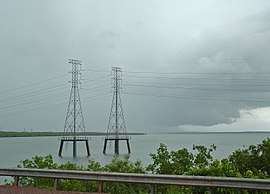
For crossing broad valleys, a large distance between the conductors must be maintained to avoid short-circuits caused by conductor cables colliding during storms. To achieve this, sometimes a separate mast or tower is used for each conductor. For crossing wide rivers and straits with flat coastlines, very tall towers must be built due to the necessity of a large height clearance for navigation. Such towers and the conductors they carry must be equipped with flight safety lamps and reflectors.
Two well-known wide river crossings are the Elbe Crossing 1 and Elbe Crossing 2. The latter has the tallest overhead line masts in Europe, at 227 m (745 ft) tall. In Spain, the overhead line crossing pylons in the Spanish bay of Cádiz have a particularly interesting construction. The main crossing towers are 158 m (518 ft) tall with one crossarm atop a frustum framework construction. The longest overhead line spans are the crossing of the Norwegian Sognefjord (4,597 m (15,082 ft) between two masts) and the Ameralik Span in Greenland (5,376 m (17,638 ft)). In Germany, the overhead line of the EnBW AG crossing of the Eyachtal has the longest span in the country at 1,444 m (4,738 ft).
In order to drop overhead lines into steep, deep valleys, inclined towers are occasionally used. These are utilized at the Hoover Dam, located in the United States, to descend the cliff walls of the Black Canyon of the Colorado. In Switzerland, a NOK pylon inclined around 20 degrees to the vertical is located near Sargans, St. Gallens. Highly sloping masts are used on two 380 kV pylons in Switzerland, the top 32 meters of one of them being bent by 18 degrees to the vertical.
Power station chimneys are sometimes equipped with crossbars for fixing conductors of the outgoing lines. Because of possible problems with corrosion by flue gases, such constructions are very rare.
A new type of pylon will be used in the Netherlands starting in 2010. The pylons were designed as a minimalist structure by Dutch architects Zwarts and Jansma. The use of physical laws for the design made a reduction of the magnetic field possible. Also, the visual impact on the surrounding landscape is reduced.[5]
Two clown-shaped pylons appear in Hungary, on both sides of the M5 motorway, near Újhartyán. (47°14′09″N 19°23′27″E / 47.2358442°N 19.3907302°E [6])
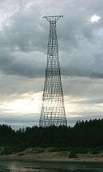 128 meters high Hyperboloid pylon in Russia
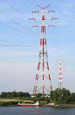 River Elbe Crossing 2 in Germany
 Wintrack pylons in the Netherlands
 The Mickey Pylon in Florida
Assembly
Before transmission towers are even erected, prototype towers are tested at tower testing stations. There are a variety of ways they can then be assembled and erected:

- They can be assembled horizontally on the ground and erected by push-pull cable. This method is rarely used because of the large assembly area needed.
- They can be assembled vertically (in their final upright position). Very tall towers, such as the Yangtze River Crossing, were assembled in this way.
- A jin-pole crane can be used to assemble lattice towers.[7] This is also used for utility poles.
- Helicopters can serve as aerial cranes for their assembly in areas with limited accessibility. Towers can also be assembled elsewhere and flown to their place on the transmission right-of-way.[8]
Markers
The International Civil Aviation Organization issues recommendations on markers for towers and the conductors suspended between them. Certain jurisdictions will make these recommendations mandatory, for example that certain power lines must have overhead wire markers placed at intervals, and that warning lights be placed on any sufficiently high towers.,[9] this is particularly true of transmission towers which are in close vicinity to airports.
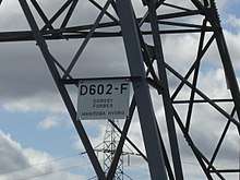
Electricity pylons often have an identification tag marked with the name of the line (either the terminal points of the line or the internal designation of the power company) and the tower number. This makes identifying the location of a fault to the power company that owns the tower easier.
Transmission towers, much like other steel lattice towers including broadcasting or cellphone towers, are marked with signs which discourage public access due to the danger of the high voltage. Often this is accomplished with a sign warning of the high voltage. At other times, the entire access point to the transmission corridor is marked with a sign. Some countries require that lattice steel towers be equipped with a barbed wire barrier approximately 3 m (9.8 ft) above ground in order to deter unauthorized climbing. Such barriers can often be found on towers close to roads or other areas with easy public access, even where there is not a legal requirement. In the United Kingdom, all such towers are fitted with barbed wire.
Tower functions
Tower structures can be classified by the way in which they support the line conductors.[10] Suspension structures support the conductor vertically using suspension insulators. Strain structures resist net tension in the conductors and the conductors attach to the structure through strain insulators. Dead-end structures support the full weight of the conductor and also all the tension in it, and also use strain insulators.
Structures are classified as tangent suspension, angle suspension, tangent strain, angle strain, tangent dead-end and angle dead-end.[2] Where the conductors are in a straight line, a tangent tower is used. Angle towers are used where a line must change direction.
Cross arms and conductor arrangement
Generally three conductors are required per AC 3-phase circuit, although single-phase and DC circuits are also carried on towers. Conductors may be arranged in one plane, or by use of several cross-arms may be arranged in a roughly symmetrical, triangulated pattern to balance the impedances of all three phases. If more than one circuit is required to be carried and the width of the line right-of-way does not permit multiple towers to be used, two or three circuits can be carried on the same tower using several levels of cross-arms. Often multiple circuits are the same voltage, but mixed voltages can be found on some structures.
Notable electricity transmission towers
The following electricity transmission towers are notable due to their enormous height, unusual design, unusual construction site or their use in artworks.
| Tower | Year | Country | Town | Pinnacle | Remarks |
|---|---|---|---|---|---|
| Zhoushan Island Overhead Powerline Tie | 2009–2010 | China | Damao Island | 370 m | Tallest pylons in the world |
| Jiangyin Yangtze River Crossing | 2003 | China | Jiangyin | 346.5 m | |
| Amazonas Crossing of Tucuruí transmission line | 2013 | Brazil | near Almeirim | 295 m[11] | Tallest electricity pylons in South America |
| Yangtze River power line crossing of Shanghai-Huainan Powerline | 2013 | China | Gaogouzhen | 269.75 m | |
| Nanjing Yangtze River Crossing | 1992 | China | Nanjing | 257 m | Tallest reinforced concrete pylons in the world |
| Pylons of Pearl River Crossing | 1987 | China | Pearl River | 253 m + 240 m | |
| Orinoco River Crossing | 1990 | Venezuela | Caroní | 240 m | |
| Pylons of Messina | 1957 | Italy | Messina | 232 m (224 m without basement) | Not used as pylons any more |
| HVDC Yangtze River Crossing Wuhu | 2003 | China | Wuhu | 229 m | Tallest electricity pylons used for HVDC |
| Elbe Crossing 2 | 1976–1978 | Germany | Stade | 227 m | Tallest electricity pylons still in use in Europe |
| Chushi Powerline Crossing | 1962 | Japan | Takehara | 226 m | Tallest electricity pylons in Japan |
| Daqi-Channel-Crossing | 1997 | Japan | Takehara | 223 m | |
| Overhead line crossing Suez Canal | 1998 | Egypt | 221 m | ||
| Kerinchi Pylon | 1999 | Malaysia | Kerinchi | 210 m | Tallest strainer pylon in the world, not part of a powerline crossing of a waterway |
| Huainan Luohe Powerline Crossing | 1989 | China | Huainan | 202.5 m | Pylons of reinforced concrete |
| Yangzi River Crossing of HVDC Xianjiaba – Shanghai | 2009 | China | ??? | 202 m[12] | |
| Balakovo 500 kV Wolga Crossing, Tower East | 1983–1984 | Russia | Balakovo | 197 m | Tallest electricity pylon in Russia and ex-USSR |
| LingBei-Channel-Crossing | 1993 | Japan | Reihoku | 195 m | |
| Doel Schelde Powerline Crossing 2 | 2019 | Belgium | Antwerpen | 192 m | Second crossing of Schelde River |
| 400 kV Thames Crossing | 1965 | UK | West Thurrock | 190 m | |
| Elbe Crossing 1 | 1958–1962 | Germany | Stade | 189 m | |
| Doel Schelde Powerline Crossing 2 | 2000 | Belgium | Antwerpen | 178 m | Crossing of a container quay |
| Tracy Saint Lawrence River Powerline Crossing | ? | Canada | Tracy | 174.6 m | Tallest electricity pylon in Canada |
| Doel Schelde Powerline Crossing 1 | 1974 | Belgium | Antwerpen | 172 m | Group of 2 towers with 1 pylon situated in the middle of Schelde River |
| Lekkerkerk Crossing 1 | 1970 | Netherlands | Lekkerkerk | 163 m | Tallest crossing in the Netherlands |
| Bosporus overhead line crossing III | 1999 | Turkey | Istanbul | 160 m | |
| Balakovo 500 kV Wolga Crossing, Tower West | 1983–1984 | Russia | Balakovo | 159 m | |
| Pylons of Cadiz | 1957–1960 | Spain | Cadiz | 160 m | |
| Maracaibo Bay Powerline Crossing | ? | Venezuela | Maracaibo | 150 m | Towers on caissons |
| Meredosia-Ipava Illinois River Crossing | 2017 | United States | Beardstown | 149.35 m | |
| Aust Severn Powerline Crossing | 1959 | UK | Aust | 148.75 m | |
| 132 kV Thames Crossing | 1932 | UK | West Thurrock | 148.4 m | Demolished in 1987 |
| Karmsundet Powerline Crossing | ? | Norway | Karmsundet | 143.5 m | |
| Limfjorden Overhead powerline crossing 2 | ? | Denmark | Raerup | 141.7 m | |
| Saint Lawrence River HVDC Quebec-New England Overhead Powerline Crossing | 1989 | Canada | Deschambault-Grondines | 140 m | Dismantled in 1992 |
| Pylons of Voerde | 1926 | Germany | Voerde | 138 m | |
| Köhlbrand Powerline Crossing | ? | Germany | Hamburg | 138 m | |
| Bremen-Farge Weser Powerline Crossing | ? | Germany | Bremen | 135 m | |
| Pylons of Ghesm Crossing | 1984 | Iran | Strait of Ghesm | 130 m | One pylon standing on a caisson in the sea |
| Shukhov tower on the Oka River | 1929 | Russia | Dzerzhinsk | 128 m | Hyperboloid structure, 2 towers, one of them demolished |
| Tarchomin pylon of Tarchomin-Łomianki Vistula Powerline Crossing | ? | Poland | Tarchomin | 127 m | |
| Skolwin pylon of Skolwin-Inoujscie Odra Powerline Crossing | ? | Poland | Skolwin | 126 m | |
| Enerhodar Dnipro Powerline Crossing 2 | 1977 | Ukraine | Enerhodar | 126 m | |
| Inoujscie pylon of Skolwin-Inoujscie Odra Powerline Crossing | ? | Poland | Inoujscie | 125 m | |
| Bosporus overhead line crossing II | 1983 | Turkey | Istanbul | 124 m | |
| Tista River Crossing | 1985 | India | Jalpaiguri | 120 m | Pile Foundation |
| Duisburg-Wanheim Powerline Rhine Crossing | ? | Germany | Duisburg | 122 m | |
| Łomianki pylon of Tarchomin-Łomianki Vistula Powerline Crossing | ? | Poland | Łomianki | 121 m | |
| Little Belt Overhead powerline crossing 2 | ? | Denmark | Middelfart | 125.3 m / 119.2 m | |
| Little Belt Overhead powerline crossing 2 | ? | Denmark | Middelfart | 119.5 m / 113.1 m | |
| Pylons of Duisburg-Rheinhausen | 1926 | Germany | Duisburg-Rheinhausen | 118.8 m | |
| Bullenhausen Elbe Powerline Crossing | ? | Germany | Bullenhausen | 117 m | |
| Lubaniew-Bobrowniki Vistula Powerline Crossing | ? | Poland | Lubaniew/Bobrowniki | 117 m | |
| Swieze Górne-Rybakow Vistula Powerline Crossing | ? | Poland | Swieze Górne/Rybaków | 116 m | |
| Ostrówek-Tursko Vistula Powerline Crossing | ? | Poland | Ostrówek/Tursko | 115 m | |
| Bosporus overhead line crossing I | 1957 | Turkey | Istanbul | 113 m | |
| Riga Hydroelectric Power Plant Crossing Pylon | 1974 | Latvia | Salaspils | 112 m | |
| Bremen-Industriehafen Weser Powerline Crossing | ? | Germany | Bremen | 111 m | Two parallel running powerlines, one used for a single phase AC powerline of Deutsche Bahn AG |
| Probostwo Dolne pylon of Nowy Bógpomóz-Probostwo Dolne Vistula Powerline Crossing | ? | Poland | Nowy Bógpomóz/Probostwo Dolne | 111 m | |
| Daugava Powerline Crossing | 1975 | Latvia | Riga | 110 m | |
| Nowy Bógpomóz pylon of Nowy Bógpomóz-Probostwo Dolne Vistula Powerline Crossing | ? | Poland | Nowy Bógpomóz | 109 m | |
| Regów Golab Vistula Powerline Crossing | ? | Poland | Regów/Golab | 108 m | |
| Orsoy Rhine Crossing | ? | Germany | Orsoy | 105 m | |
| Limfjorden Overhead powerline crossing 1 | ? | Denmark | Raerup | 101.2 m | |
| Enerhodar Dnipro Powerline Crossing 2 | 1977 | Ukraine | Enerhodar | 100 m | Pylons standing on caissons |
| Reisholz Rhine Powerline Crossing | 1917 | Germany | Düsseldorf | ? | Under the legs of the pylon on the east shore of Rhine there runs the rail to nearby Holthausen substation |
| Sone River Crossing | 1983 | India | Sone Bhadra (Uttar Pradesh) | 96 m | Pylons standing on Well Foundation |
| Strelasund Powerline Crossing | ? | Germany | Sundhagen | 85 m | Pylons standing on caissons |
| 380 kV Ems Overhead Powerline Crossing | ? | Germany | Mark (south of Weener) | 84 m | |
| Pylon in the artificial lake of Santa Maria | 1959 | Switzerland | Lake of Santa Maria | 75 m | Pylon in an artificial lake |
| Zaporizhzhia Pylon Triple | ? | Ukraine | Zaporizhzhia | 74.5 m | Two triple pylons used for a powerline crossing from Khortytsia Island to the east shore of Dneipr |
| Aggersund Crossing of Cross-Skagerrak | 1977 | Denmark | Aggersund | 70 m | Tallest pylons used for HVDC-transmission in Europe |
| Eyachtal Span | 1992 | Germany | Höfen | 70 m | Longest span of Germany (1444 metres) |
| Leaning pylon of Mingjian | ? | Taiwan | Mingjian | ? | Earthquake memorial |
| Carquinez Strait Powerline Crossing | 1901 | United States | Benicia | 68 m + 20 m | World's first powerline crossing of a larger waterway |
| Pylon 310 of powerline Innertkirchen-Littau-Mettlen | 1990 | Switzerland | Littau | 59,5 m | Tallest pylon of prefabricated concrete |
| Anlage 2610, Mast 69 | ? | Germany | Bochum | 47 m | Pylon of 220 kV powerline decorated with balls in Ruhr-Park mall. |
| Colossus of Eislingen | 1980 | Germany | Eislingen/Fils | 47 m | Pylon standing over a small river |
| Pylon 24 of powerline Watari-Kashiwabara | ? | Japan | Uchihara, Ibaraki | 45 m | Pylon standing over a public road with two lanes |
| Mickey Pylon | 1996 | USA | Celebration, Florida | 32 m | Mickey mouse shaped pylon |
| Source[13] | 2004 | France | Amnéville les Thermes | 34 m / 28 m | 4 pylons forming an artwork |
| Huddersfield Narrow Canal Pylon | 1967 | UK | Stalybridge, Greater Manchester | ? | Pylon standing over a waterway shipable by small boats |
See also
References
- 1 2 "Environmental, Health, and Safety Guidelines for Electric Power Transmission and Distribution" (PDF). International Finance Corporation. 2007-04-30. p. 21. Retrieved 2013-09-15.
- 1 2 3 Donald Fink and Wayne Beaty (ed.) Standard Handbook for Electrical Engineers 11th Ed., Mc Graw Hill, 1978, ISBN 0-07-020974-X, pp. 14-102 and 14-103
- ↑ http://www.spta.org/pdf/Reisdorff%20Lam%20%209-11.pdf
- ↑ Olive Development. "Winterport, Maine".
- ↑ "New High Voltage Pylons for the Netherlands". 2009. Retrieved 2010-04-24.
- ↑ "Clown-shaped High Voltage Pylons in Hungary".
- ↑ Broadcast Tower Technologies. "Gin Pole Services". Retrieved 2009-10-24.
- ↑ "Powering Up – Vertical Magazine". verticalmag.com. Archived from the original on 4 October 2015. Retrieved 4 October 2015.
- ↑ "Chapter 6. Visual aids for denoting obstacles" (PDF). Annex 14 Volume I Aerodrome design and operations. International Civil Aviation Organization. 2004-11-25. pp. 6–3, 6–4, 6–5. Retrieved 1 June 2011.
6.2.8 ... spherical ... diameter of not less than 60 cm. ... 6.2.10 ... should be of one colour. ... Figure 6-2 ... 6.3.13
- ↑ American Society of Civil Engineers Design of latticed steel transmission structures ASCE Standard 10-97, 2000, ISBN 0-7844-0324-4, section C2.3
- ↑ "Concluída primeira torre da linha entre Manaus e Macapá". Archived from the original on 2015-06-12.
- ↑ CS Tower. "Projects – CS Tower – A leading Steel Tower Manufacturer in the World".
- ↑ http://electric-art.eu/
External links
| Wikimedia Commons has media related to Electricity pylons. |
- Electricity pylons in Hungary
- Pylon Appreciation Society
- Flash Bristow's pylon photo gallery and pylon FAQ
- Magnificent Views: Pictures of High Voltage Towers (also offers technical information)
- Structurae database of select notable transmission towers
- Pylons in Russia and other areas of former Soviet Union
- Collection of some electricity pylons on Skyscraperpage.com
- Meet the 'pylon spotters' – BBC News