Residual-current device

| Relevant topics on |
| Electrical installations |
|---|
| Wiring practice by region or country |
| Regulation of electrical installations |
| Cabling and accessories |
| Switching and protection devices |
A residual-current device (RCD), or residual-current circuit breaker (RCCB), is a device that instantly breaks an electric circuit to prevent serious harm from an ongoing electric shock. Injury may still occur in some cases, for example if a human falls after receiving a shock.
In the United States and Canada, the device is called a ground fault circuit interrupter (GFCI), ground fault interrupter (GFI) or an appliance leakage current interrupter (ALCI). In the United Kingdom, these devices are known by their initials RCD, and a combined RCD+MCB (miniature circuit breaker) is known as a RCBO (residual-current circuit breaker with overcurrent protection). In Australia a protection device with this function is called a Safety Switch or RCD.
An earth leakage circuit breaker (ELCB) may be a residual-current device, although an older type of voltage-operated earth leakage circuit breaker also exists.
These electrical wiring devices are designed to quickly and automatically disconnect a circuit when it detects that the electric current is not balanced between the supply and return conductors of a circuit. Any difference between the currents in these conductors indicates leakage current, which presents a shock hazard. A current of around 30 mA (0.030 amperes) is potentially sufficient to cause cardiac arrest or serious harm if it persists for more than a small fraction of a second. RCDs are designed to disconnect the conducting wires ("trip") quickly enough to prevent serious injury.
An RCD does not provide protection against overcurrent (overload) or short circuit in the circuit, and so cannot replace a fuse. RCDs are often integrated with some kind of circuit breaker, such as a fuse or miniature circuit breaker (MCB), which protects against excess current in the circuit. (Where both functions are provided in the same device, the resulting RCD with overcurrent protection called an RCBO). RCDs also cannot detect a human accidentally touching both conductors at the same time.
RCDs are testable and resettable devices. A test button safely creates a small leakage condition, and a reset button reconnects the conductors after a fault condition has been cleared. Some RCDs disconnect both the energized and return conductors upon a fault (double pole), while a single pole RCD only disconnects the energized conductor. If the fault has left the return wire "floating" or not at its expected ground potential for any reason, then a single-pole RCD will leave this conductor still connected to the circuit when it detects the fault.
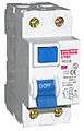 A two-pole, or double-pole, residual-current device. The test button and connect/disconnect switch are colored blue. A fault will trigger the switch to its down (off) position, which in this device would disconnect both conductors.
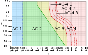 Log-log graph of the effect of alternating current I of duration T passing from left hand to feet as defined in IEC publication 60479-1.[1]
 1: Electromagnet with help electronics
2: Current transformer secondary winding
3: Transformer core
4: Test push-button
L: Line conductor
N: Neutral conductor
Purpose and operation
RCDs are designed to disconnect the circuit if there is a leakage current.[2] By detecting small leakage currents (typically 5–30 mA) and disconnecting quickly enough (<30 ms), they may prevent electrocution.[3] They are an essential part of the automatic disconnection of supply (ADS), i.e. to switch off when a fault develops, rather than rely on human intervention, one of the essential tenets of modern electrical practice.[4]
To prevent electrocution, RCDs should operate within 25–40 milliseconds with any leakage currents (through a person) of greater than 30 mA, before electric shock can drive the heart into ventricular fibrillation, the most common cause of death through electric shock. By contrast, conventional circuit breakers or fuses only break the circuit when the total current is excessive (which may be thousands of times the leakage current an RCD responds to). A small leakage current, such as through a person, can be a very serious fault, but would probably not increase the total current enough for a fuse or circuit breaker to break the circuit, and certainly not do so fast enough to save a life.
RCDs operate by measuring the current balance between two conductors using a differential current transformer. This measures the difference between current flowing through the live conductor and that returning through the neutral conductor. If these do not sum to zero, there is a leakage of current to somewhere else (to earth/ground or to another circuit), and the device will open its contacts. Operation does not require a fault current to return through the earth wire in the installation; the trip will operate just as well if the return path is through plumbing, contact with the ground or any other current path. Automatic disconnection and a measure of shock protection is therefore still provided even if the earth wiring of the installation is damaged or incomplete.
Residual-current detection is complementary to over-current detection. Residual-current detection cannot provide protection for overload or short-circuit currents, except for the special case of a short circuit from live to ground (not live to neutral).
For a RCD used with three-phase power, all three live conductors and the neutral (if fitted) must pass through the current transformer.
Application
A ground fault circuit interrupter circuit breaker (GFCI breaker in USA and Canada) and residual-current breaker with overload (RCBO in Europe) are devices that combine the functions of a residual-current device with a circuit breaker. They detect both supply imbalance and overload current.
In Europe, RCDs can fit on the same DIN rail as the MCBs, however the busbar arrangements in consumer units and distribution boards can make it awkward to use them in this way. If it is desired to protect an individual circuit, an RCBO (residual-current circuit breaker with overcurrent protection) can be used. This incorporates an RCD and a miniature circuit breaker in one device.
Electrical plugs with incorporated RCD are sometimes installed on appliances that might be considered to pose a particular safety hazard, for example long extension leads, which might be used outdoors, or garden equipment or hair dryers, which may be used near a bath or sink. Occasionally an in-line RCD may be used to serve a similar function to one in a plug. By putting the RCD in the extension lead, protection is provided at whatever outlet is used even if the building has old wiring, such as knob and tube, or wiring that does not contain a grounding conductor.
In North America, GFI receptacles can be used in cases where there is no grounding conductor, but they must be labeled as "ungrounded". An ungrounded GFI receptacle will trip using the built-in "test" button, but will not trip using a GFI test plug, because the plug tests by passing a small current from line to the non-existent ground.
Electrical sockets with included RCDs are becoming common.
Typical design
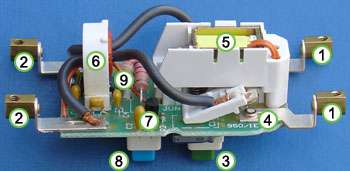

The diagram depicts the internal mechanism of a residual-current device (RCD). The device is designed to be wired in-line in an appliance power cord. It is rated to carry a maximal current of 13 A and is designed to trip on a leakage current of 30 mA. This is an active RCD; that is, it latches electrically and therefore trips on power failure, a useful feature for equipment that could be dangerous on unexpected re-energisation. Some early RCDs were entirely electromechanical and relied on finely balanced sprung over-centre mechanisms driven directly from the current transformer. As these are hard to manufacture to the required accuracy and prone to drift in sensitivity both from pivot wear and lubricant dry-out, the electronically amplified type with a more robust solenoid part as illustrated are now dominant.
The incoming supply and the neutral conductors are connected to the terminals at (1), and the outgoing load conductors are connected to the terminals at (2). The earth conductor (not shown) is connected through from supply to load uninterrupted. When the reset button (3) is pressed, the contacts ((4) and another, hidden behind (5)) close, allowing current to pass. The solenoid (5) keeps the contacts closed when the reset button is released.
The sense coil (6) is a differential current transformer which surrounds (but is not electrically connected to) the live and neutral conductors. In normal operation, all the current down the live conductor returns up the neutral conductor. The currents in the two conductors are therefore equal and opposite and cancel each other out.
Any fault to earth (for example caused by a person touching a live component in the attached appliance) causes some of the current to take a different return path, which means that there is an imbalance (difference) in the current in the two conductors (single-phase case), or, more generally, a nonzero sum of currents from among various conductors (for example, three phase conductors and one neutral conductor).
This difference causes a current in the sense coil (6), which is picked up by the sense circuitry (7). The sense circuitry then removes power from the solenoid (5), and the contacts (4) are forced apart by a spring, cutting off the electricity supply to the appliance.
The test button (8) allows the correct operation of the device to be verified by passing a small current through the orange test wire (9). This simulates a fault by creating an imbalance in the sense coil. If the RCD does not trip when this button is pressed, then the device must be replaced.
RCD with additional overcurrent protection circuitry (RCBO or GFCI breaker)
Residual-current and overcurrent protection may be combined in one device for installation into the service panel; this device is known as a GFCI (ground fault circuit interrupter) breaker in the USA and Canada, and as an RCBO (residual-current circuit breaker with overload protection) in Europe. In the US, GFCI breakers are more expensive than GFCI outlets.
As well as requiring both line and neutral inputs and outputs (or, full 3-phase), many GFCI/RCBO devices require a functional earth (FE) connection. This serves to provide both EMC immunity and to reliably operate the device if the input-side neutral connection is lost but live and earth remain.
For reasons of space, many devices, especially in DIN rail format, use flying leads rather than screw terminals, especially for the neutral input and FE connections. Additionally, because of the small form factor, the output cables of some models (Eaton/MEM) are used to form the primary winding of the RCD part, and the outgoing circuit cables must be led through a specially dimensioned terminal tunnel with the current transformer part around it. This can lead to incorrect failed trip results when testing with meter probes from the screw heads of the terminals, rather than from the final circuit wiring.
Having one RCD feeding another is generally unnecessary, provided they have been wired properly. One exception is the case of a TT earthing system, where the earth loop impedance may be high, meaning that a ground fault might not cause sufficient current to trip an ordinary circuit breaker or fuse. In this case a special 100 mA (or greater) trip current time-delayed RCD is installed, covering the whole installation, and then more sensitive RCDs should be installed downstream of it for sockets and other circuits that are considered high-risk.
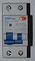 CHINT's RCBO
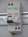 Schneider Electric
 Shihlin Electric
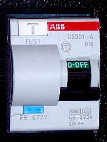 ABB
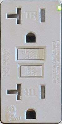
ABB Typical US AFCI/GFCI
RCD with additional arc fault protection circuitry
In addition to Ground Fault Circuit Interrupters (GFCIs), Arc-fault circuit interrupter devices (AFCI) are equally important as they offer added protection from potentially hazardous arc-faults resulting from damage in branch circuit wiring as well as extensions to branches such as appliances and cord sets. By detecting hazardous arc-faults and responding by interrupting power, AFCIs helps reduce the likelihood of the home's electrical system being an ignition source of a fire. Dual Function AFCI/GFCI devices offer both electrical fire prevention and shock prevention in one device making them a solution for many rooms in the home, especially when replacing an existing standard receptacle or existing ungrounded receptacle.
Common features and variations
Differences in disconnection actions
Major differences exist regarding the manner in which an RCD-unit will act to disconnect the power to a circuit or appliance.
There are four situations in which different types of RCD-units are used:
1. At the Consumer Power-Distribution Unit (CPDU) - usually in conjunction with an RCBO resettable circuit breaker 2. Built into a wall socket 3. Plugged into a wall socket, which may be part of a power-extension cable. 4. Built into the cord of a portable appliance, such as those intended to be used in outdoor or wet areas.
The first three of those situations, relate largely to usage as part of a power-distribution system & are almost always of the 'Passive' (or otherwise 'Latched') variety, whereas the fourth relates solely to specific appliances, & SHOULD always be of the 'Active' (or otherwise 'non-Latching') variety. The 'Active' tag relates to the prevention of any 're-activation' of the power-supply after any inadvertent form of power outage, as soon as the mains supply becomes re-established; the 'Latch' tag relates to a 'switch' inside the 'RCD-unit' that remains as set following any form of 'regular' power-outage, but has to be reset manually after the detection of an error-condition.
In the fourth situation, it would be deemed to be highly undesirable, & probably very unsafe, for a connected appliance to automatically resume operation after ANY sort of power-disconnection, without having the operator in attendance - so manual reactivation of the 'RCD-unit' is ALWAYS necessary.
The difference between the modes of operation of the essentially two different-types of 'RCD-unit' functionality, is that the operation for power-distribution purposes requires the internal 'Latch' to remain set within the 'RCD-unit' after any form of power-disconnection caused by either the user himself turning the power off, or after any power-outage attributable to the electricity service-provider; such arrangements are particularly applicable for connections to refrigerators & freezers.
Situation two is mostly installed just as described above, but some wall-socket 'RCD-units' are available to fit the 'Type 4' situation, often by operating a switch on the fascia panel.
RCD-units for the 'Type 1 to 3' situation are most commonly rated at 30-milli-amps & 40-milli-seconds (being the degree of power protection, & the time taken before the cut-out operates). For 'Type 4', there is generally a greater choice of 'settings' available - generally all 'lower' than the other forms, but lower values often result in more nuisance tripping. Sometimes users apply 'Type 4' protection in addition to one of the other forms, when they wish to over-ride those with a lower rating. The 'Type 4' type of protection is also utilised by 'Travellers', particularly when using foreign power supplies, or anywhere else where they cannot rely upon the presence of protection being supplied at the CPDU &c.. It may be wise to have a selection of 'Type 4' 'RCD-units' available, because connections made under damp conditions or using lengthy power-cables are more prone to trip-out when any of the lower-ratings of 'RCD-unit' are used; ratings as low as 10-milli-amps are available. It never does any harm to include more than one 'RCD-unit' within any circuitry, but solely the unit having the lowest rating will be relevant.
Number of poles and pole terminology
The number of poles represents the number of conductors that are interrupted when a fault condition occurs. RCDs used on single-phase AC supplies (two current paths), such as domestic power, are usually one- or two-pole designs, also known as single- and double-pole. A single-pole RCD interrupts only the energized conductor, while a double-pole RCD interrupts both the energized and return conductors. (In a single-pole RCD, the return conductor is usually anticipated to be at ground potential at all times and therefore safe on its own, however see limitations below).
RCDs with three or more poles can be used on three-phase AC supplies (three current paths) or to disconnect an earth conductor as well, with four-pole RCDs used to interrupt three-phase + neutral supplies. Specially designed RCDs can also be used with both AC and DC power distribution systems.
The following terms are sometimes used to describe the manner in which conductors are connected and disconnected by an RCD:
- Single-pole / SP / one-pole - the RCD will disconnect the energized wire only.
- Double-pole / DP / two-pole - the RCD will disconnect both the energized and return wires.
- 1+N and 1P+N – non-standard terms used in the context of RCBOs, at times used differently by different manufacturers. Typically these terms may signify that the return (neutral) conductor is an isolating pole only, without a protective element (an unprotected but switched neutral), or that the RCBO provides a conducting path and connectors for the return (neutral) conductor but this path remains uninterrupted when a fault occurs (sometimes known as "solid neutral"),[5] or that both conductors are disconnected for some faults (such as RCD detected leakage) but only one conductor is disconnected for other faults (such as overload).[6]
Sensitivity
RCD sensitivity is expressed as the rated residual operating current, noted IΔn. Preferred values have been defined by the IEC, thus making it possible to divide RCDs into three groups according to their IΔn value:
- high sensitivity (HS): 5** – 10 – 30 mA (for direct-contact / life injury protection),
- medium sensitivity (MS): 100 – 300 – 500 – 1000 mA (for fire protection),
- low sensitivity (LS): 3 – 10 – 30 A (typically for protection of machine).
The 5 mA sensitivity is typical for GFCI outlets.
Break time (response speed)
There are two groups of devices. G (general use) instantaneous RCDs have no intentional time delay. They must never trip at one-half of the nominal current rating, but must trip within 200 milliseconds for rated current, and within 40 milliseconds at five times rated current. S (selective) or T (time-delayed) RCDs have a short time delay. They are typically used at the origin of an installation for fire protection to discriminate withGdevices at the loads, and in circuits containing surge suppressors. They must not trip at one-half of rated current. They provide at least 130 milliseconds delay of tripping at rated current, 60 milliseconds at twice rated, and 50 milliseconds at five times rated. The maximum break time is 500 ms at rated current, 200 ms at twice rated, and 150 ms at five times rated.
Programmable earth fault relays are available to allow co-ordinated installations to minimise outage. For example a power distribution system might have a 300 mA, 300 ms device at the service entry of a building, feeding several 100 mA S type at each sub-board, and 30 mA G type for each final circuit. In this way, a failure of a device to detect the fault will eventually be cleared by a higher-level device, at the cost of interrupting more circuits.
Type, or mode (types of current leakage issue detected)
IEC Standard 60755 (General requirements for residual current operated protective devices) defines three types of RCD depending on the waveforms and frequency of the fault current. Type AC RCDs trip on sinusoidal residual current. Type A RCDs also respond to pulsating or continuous direct current of either polarity. Type BRCDs also respond to higher frequency current, or for combinations of alternating and direct current as may be found from single-phase or multi-phase rectifying circuits, like all the switching power suplies used at home,or for example washing machines etc., equipped with dc- motors.
Surge current resistance
The surge current refers to the peak current an RCD is designed to withstand using a test impulse of specified characteristics. The IEC 61008 and IEC 61009 standards require that RCDs withstand a 200 ampere "ring wave" impulse. The standards also require RCDs classified as "selective" to withstand a 3000 amp impulse surge current of specified waveform.
Testing of correct operation
RCDs can be tested with built-in test button to confirm functionality on a regular basis. RCDs may not operate correctly if wired improperly, so they are generally tested by the installer to verify correct operation. Use of a solenoid voltmeter from live to earth provides an external path and can test the wiring to the RCD. Such a test may be performed on installation of the device and at any "downstream" outlet. (Upstream outlets are not protected.) To avoid needless tripping, only one RCD should be installed on any single circuit (excluding corded RCDs, such as bathroom small appliances).
Limitations
A residual-current circuit breaker cannot remove all risk of electric shock or fire. In particular, an RCD alone will not detect overload conditions, phase-to-neutral short circuits or phase-to-phase short circuits (see three-phase electric power). Over-current protection (fuses or circuit breakers) must be provided. Circuit breakers that combine the functions of an RCD with overcurrent protection respond to both types of fault. These are known as RCBOs and are available in 2-, 3- and 4-pole configurations. RCBOs will typically have separate circuits for detecting current imbalance and for overload current but use a common interrupting mechanism.
An RCD helps to protect against electric shock when current flows through a person from a phase (live / line / hot) to earth. It cannot protect against electric shock when current flows through a person from phase to neutral or from phase to phase, for example where a finger touches both live and neutral contacts in a light fitting; a device cannot differentiate between current flow through an intended load from flow through a person, though the RCD may still trip if the person is in contact with the ground (earth), as some current may still pass through the persons finger and body to earth.
Whole installations on a single RCD, common in older installations in the UK, are prone to "nuisance" trips that can cause secondary safety problems with loss of lighting and defrosting of food. Frequently the trips are caused by deteriorating insulation on heater elements, such as water heaters and cooker elements or rings. Although regarded as a nuisance, the fault is with the deteriorated element and not the RCD: replacement of the offending element will resolve the problem, but replacing the RCD will not.
In the case of RCDs that need a power supply, a dangerous condition can arise if the neutral wire is broken or switched off on the supply side of the RCD, while the corresponding live wire remains uninterrupted. The tripping circuit needs power to work and does not trip when the power supply fails. Connected equipment will not work without a neutral, but the RCD cannot protect people from contact with the energized wire. For this reason circuit breakers must be installed in a way that ensures that the neutral wire cannot be switched off unless the live wire is also switched off at the same time. Where there is a requirement for switching off the neutral wire, two-pole breakers (or four-pole for 3-phase) must be used. To provide some protection with an interrupted neutral, some RCDs and RCBOs are equipped with an auxiliary connection wire that must be connected to the earth busbar of the distribution board. This either enables the device to detect the missing neutral of the supply, causing the device to trip, or provides an alternative supply path for the tripping circuitry, enabling it to continue to function normally in the absence of the supply neutral.
Related to this, a single-pole RCD/RCBO interrupts the energized conductor only, while a double-pole device interrupts both the energized and return conductors. Usually this is a standard and safe practice, since the return conductor is held at ground potential anyway. However, because of its design, a single-pole RCD will not isolate or disconnect all relevant wires in certain uncommon situations, for example where the return conductor is not being held, as expected, at ground potential, or where current leakage occurs between the return and earth conductors. In these cases, a double-pole RCD will offer protection, since the return conductor would also be disconnected.
History and nomenclature
The world’s first high-sensitivity earth leakage protection system (i.e. a system capable of protecting people from the hazards of direct contact between a live conductor and earth), was a second-harmonic magnetic amplifier core-balance system, known as the magamp, developed in South Africa by Henri Rubin. Electrical hazards were of great concern in South African gold mines, and Rubin, an engineer at the company C.J. Fuchs Electrical Industries of Alberton Johannesburg, initially developed a cold-cathode system in 1955 which operated at 525 V and had a tripping sensitivity of 250 mA. Prior to this, core balance earth leakage protection systems operated at sensitivities of about 10 A.
The cold cathode system was installed in a number of gold mines and worked reliably. However, Rubin began working on a completely novel system with greatly improved sensitivity, and by early 1956, he had produced a prototype second-harmonic magnetic amplifier-type core balance system (South African Patent No. 2268/56 and Australian Patent No. 218360). The prototype magamp was rated at 220 V, 60 A and had an internally adjustable tripping sensitivity of 12.5–17.5 mA. Very rapid tripping times were achieved through a novel design, and this combined with the high sensitivity was well within the safe current-time envelope for ventricular fibrillation determined by Charles Dalziel of the University of California, Berkeley, USA, who had estimated electrical shock hazards in humans. This system, with its associated circuit breaker, included overcurrent and short-circuit protection. In addition, the original prototype was able to trip at a lower sensitivity in the presence of an interrupted neutral, thus protecting against an important cause of electrical fire.
Following the accidental electrocution of a woman in a domestic accident at the Stilfontein gold mining village near Johannesburg, a few hundred F.W.J. 20 mA magamp earth leakage protection units were installed in the homes of the mining village during 1957 and 1958. F.W.J. Electrical Industries, which later changed its name to FW Electrical Industries, continued to manufacture 20 mA single phase and three phase magamp units.
At the time that he worked on the magamp, Rubin also considered using transistors in this application, but concluded that the early transistors then available were too unreliable. However, with the advent of improved transistors, the company that he worked for and other companies later produced transistorized versions of earth leakage protection.
In 1961, Dalziel, working with Rucker Manufacturing Co., developed a transistorized device for earth leakage protection which became known as a Ground Fault Circuit Interrupter (GFCI), sometimes colloquially shortened to Ground Fault Interrupter (GFI). This name for high-sensitivity earth leakage protection is still in common use in the U.S.A.[7][8][9][10][11]
In the early 1970s most North American GFCI devices were of the circuit breaker type. GFCIs built into the outlet receptacle became commonplace beginning in the 1980s. The circuit breaker type, installed into a distribution panel, suffered from accidental trips mainly caused by poor or inconsistent insulation on the wiring. False trips were frequent when insulation problems were compounded by long circuit lengths. So much current leaked along the length of the conductors' insulation that the breaker might trip with the slightest increase of current imbalance. The migration to outlet receptacle based protection in North American installations reduced the accidental trips and provided obvious verification that wet areas were under electrical code-required protection. European installations continue to use primarily RCDs installed at the distribution board, which provides protection in case of damage to fixed wiring; In Europe socket-based RCDs are primarily used for retro-fitting.
Regulation and adoption
Regulations differ widely from country to country. In most countries, not all circuits in a home are protected by RCDs. If a single RCD is installed for an entire electrical installation, any fault may cut all power to the premises.
Australia
In Australia, residual current devices have been mandatory on power circuits since 1991 and on light circuits since 2000.[12] A minimum of two RCDs is required per domestic installation. All socket outlets and lighting circuits are to be distributed over circuit RCDs. A maximum of three subcircuits only, may be connected to a single RCD.
Austria
Austria regulated residual current devices in the ÖVE E8001-1/A1:2013-11-01 norm (most recent revision). It has been required in private housing since 1980. The maximum activation time must not exceed 0.4 seconds. It needs to be installed on all circuits with power plugs with a maximum leakage current of 30 mA and a maximum rated current of 16 A.[13]
Additional requirements are placed on circuits in wet areas, construction sites and commercial buildings.
Belgium
Belgian domestic installations are required to be equipped with a 300 mA residual current device that protects all circuits. Furthermore, at least one 30 mA residual current device is required that protects all circuits in "wet rooms" (e.g. bathroom, kitchen) as well as circuits that power certain "wet" appliances (washing machine, tumble dryer, dishwasher). Electrical underfloor heating is required to be protected by a 100 mA RCD. These RCDs must be of type A.
Brazil
Since NBR 5410 (1997) residual current devices and grounding are required for new construction or repair in wet areas, outdoor areas, interior outlets used for external appliances, or in areas where water is more probable like bathrooms and kitchens.[14]
Denmark
Denmark requires 30 mA RCDs on all circuits that are rated for less than 20 A (circuits at greater rating are mostly used for distribution). RCDs became mandatory in 1975 for new buildings, and then for all buildings in 2008.
Germany
Since 1 May 1984, RCDs are mandatory for all rooms with a bath tub or a shower. Since June 2007 Germany requires the use of RCDs with a trip current of no more than 30 mA on sockets rated up to 32 A which are for general use. (DIN VDE 0100-410 Nr. 411.3.3). It isn't allowed to use type "AC" RCD's since 1987, to be used to protect humans against electrical shocks. It must be Type "A" or type "B".
India
According to Regulation 36 of the Electricity Regulations 1990
a) For a place of public entertainment, protection against earth leakage current must be provided by a residual current device of sensitivity not exceeding 10 mA.
b) For a place where the floor is likely to be wet or where the wall or enclosure is of low electrical resistance, protection against earth leakage current must be provided by a residual current device of sensitivity not exceeding 10 mA.
c) For an installation where hand-held equipment, apparatus or appliance is likely to be used, protection against earth leakage current must be provided by a residual current device of sensitivity not exceeding 30 mA.
d)For an installation other than the installation in (a), (b) and (c), protection against earth leakage current must be provided by a residual current device of sensitivity not exceeding 100 mA.
Italy
The Italian law (n. 46 March 1990) prescribes RCDs with no more than 30 mA residual current (informally called "salvavita" — life saver, after early Bticino models, or differential circuit breaker for the mode of operation) for all domestic installations to protect all the lines. The law was recently updated to mandate at least two separate RCDs for separate domestic circuits. Short-circuit and overload protection has been compulsory since 1968.
New Zealand
From January 2003, all new circuits originating at the switchboard supplying lighting or socket outlets (power points) in domestic buildings must have RCD protection. Residential facilities (such as boarding houses, hospitals, hotels and motels) will also require RCD protection for all new circuits originating at the switchboard supplying socket outlets. These RCDs will normally be located at the switchboard. They will provide protection for all electrical wiring and appliances plugged into the new circuits.[15]
North America
In North America receptacles located in places where an easy path to ground exists—such as wet areas and rooms with uncovered concrete floors—must be protected by a GFCI. The US National Electrical Code has required devices in certain locations to be protected by GFCIs since the 1960s. Beginning with underwater swimming pool lights (1968) successive editions of the code have expanded the areas where GFCIs are required to include: construction sites (1974), bathrooms and outdoor areas (1975), garages (1978), areas near hot tubs or spas (1981), hotel bathrooms (1984), kitchen counter receptacles (1987), crawl spaces and unfinished basements (1990), near wet bar sinks (1993), near laundry sinks (2005)[16] and in laundry rooms (2014).[17]
GFCIs are commonly available as an integral part of a receptacle or a circuit breaker installed in the distribution panelboard. GFCI receptacles invariably have rectangular faces and accept so-called Decora face plates, and can be mixed with regular outlets or switches in a multi-gang box with standard cover plates. In both Canada and the US older two-wire, ungrounded NEMA 1 receptacles may be replaced with NEMA 5 receptacles protected by a GFCI (integral with the receptacle or with the corresponding circuit breaker) in lieu of rewiring the entire circuit with a grounding conductor. In such cases the receptacles must be labeled "no equipment ground" and "GFCI protected"; GFCI manufacturers typically provide tags for the appropriate installation description.
GFCIs approved for protection against electric shock trip at 5 mA within 25 ms. A GFCI device which protects equipment (not people) is allowed to trip as high as 30 mA of current; this is known as an Equipment Protective Device (EPD). RCDs with trip currents as high as 500 mA are sometimes deployed in environments (such as computing centers) where a lower threshold would carry an unacceptable risk of accidental trips. These high-current RCDs serve for equipment and fire protection instead of protection against the risks of electrical shocks.
In the United States the American Boat and Yacht Council requires both GFCIs for outlets and Equipment Leakage Circuit Interrupters (ELCI) for the entire boat. The difference is GFCIs trip on 5 mA of current whereas ELCIs trip on 30 mA after up to 100 ms. The greater values are intended to provide protection while minimizing nuisance trips.[18]
Norway
In Norway, it has been required in all new homes since 2002, and on all new sockets since 2006. This applies to 32A sockets and below. The RCD must trigger after a maxium 0.4 seconds for 230V circuits, or 0.2 seconds for 400V circuits.
South Africa
South Africa mandated the use of Earth Leakage Protection devices in residential environments (e.g. houses, flats, hotels, etc.) from October 1974, with regulations being refined in 1975 and 1976. [19] Devices need to be installed in new premises and when repairs are carried out. Protection is required for power outlets and lighting, with the exception of emergency lighting that should not be interrupted. The standard device used in South Africa is indeed a hybrid of ELPD and RCCB.[20]
Turkey
Turkey requires the use of RCDs with no more than 30 mA and 300 mA in all new homes since 2004. This rule was introduced in RG-16/06/2004-25494.[21]
United Kingdom
The previous 16th Edition of the IEE Electrical Wiring Regulations required use of RCDs for socket outlets that were liable to be used by outdoor appliances. Normal practice in domestic installations was to use a single RCD to cover all the circuits requiring RCD protection (typically sockets and showers) but to have some circuits (typically lighting) not RCD protected.[22] This was to avoid a potentially dangerous loss of lighting should the RCD trip. Protection arrangements for other circuits varied. To implement this arrangement it was common to install a consumer unit incorporating an RCD in what is known as a split load configuration, where one group of circuit breakers is supplied direct from the main switch (or time delay RCD in the case of a TT earth) and a second group of circuits is supplied via the RCD. This arrangement had the recognised problems that cumulative earth leakage currents from the normal operation of many items of equipment could cause spurious tripping of the RCD, and that tripping of the RCD would disconnect power from all the protected circuits.
The current edition (17th) of the regulations requires that all socket outlets in most domestic installations have RCD protection, though there are exemptions. Cables buried in walls must also be RCD protected (again with some specific exemptions). {Refer to 17th Edition Amendment 1 effective from January 2012} Provision of RCD protection for circuits present in bathrooms and shower rooms reduces the requirement for supplementary bonding in those locations. Two RCDs may be used to cover the installation, with upstairs and downstairs lighting and power circuits spread across both RCDs. When one RCD trips, power is maintained to at least one lighting and power circuit. Other arrangements, such as the use of RCBOs, may be employed to meet the regulations. The new requirements for RCDs do not affect most existing installations unless they are rewired, the distribution board is changed, a new circuit is installed, or alterations are made such as additional socket outlets or new cables buried in walls.
RCDs used for shock protection must be of the 'immediate' operation type (not time-delayed) and must have a residual current sensitivity of no greater than 30 mA.
If spurious tripping would cause a greater problem than the risk of the electrical accident the RCD is supposed to prevent (examples might be a supply to a critical factory process, or to life support equipment), RCDs may be omitted, providing affected circuits are clearly labelled and the balance of risks considered, this may include the provision of alternative safety measures.
See also
References
- ↑ Weineng Wang, Zhiqiang Wang, Xiao Peng, Effects of the Earth Current Frequency and Distortion on Residual Current Devices, Scientific Journal of Control Engineering, Dec 2013, Vol. 3, Issue 6, p. 417–422.
- ↑ Ken Oldham Smith; John M. Madden (15 April 2008). Electrical Safety and the Law. John Wiley & Sons. pp. 186–. ISBN 978-0-470-77746-6.
- ↑ Joachim H. Nagel; William M. Smith (1991). Proceedings of the Annual International Conference of the IEEE Engineering in Medicine and Biology Society. IEEE. ISBN 978-0-7803-0216-7.
- ↑ Bill Atkinson; Roger Lovegrove; Gary Gundry (26 November 2012). Electrical Installation Designs. John Wiley & Sons. pp. 114–. ISBN 978-1-118-47776-2.
- ↑ Explanation on voltimum.com.au, by specialist Ian Richardson.
- ↑ http://docs-asia.electrocomponents.com/webdocs/01e3/0900766b801e3b4d.pdf (states that there is "2 pole switching of phase [energized] and neutral [return]", but then only identifies the energized conductor as being protected against "overloads and short circuits").
- ↑ Charles F. Dalziel, Transistorized ground-fault interrupter reduces shock hazard, IEEE Spectrum, January 1970
- ↑ The Professional Engineer, Official Journal of the Federation of Societies of Professional Engineers of South Africa, pp 67, Vol 6(2) 1977
- ↑ Earl W. Roberts, Overcurrents and Undercurrents – All about GFCIs: Electrical Safety Advances through Electronics, Mystic Publications, Mystic CT, 1996
- ↑ Edward L. Owen, Power System Grounding Part II: RCD & GFCI, IEEE Industry Applications Magazine, July/August 1996
- ↑ Forging ahead: South Africa’s Pioneering Engineers, G R Bozzoli, Witwatersrand University Press, 1997
- ↑ SAA Wiring Rules AS/NZS 3000:2007, Including Amendments 1 & 2, SAI Global Limited
- ↑ ÖVE E8001-1/A1:2013-11-01
- ↑ "Quando o uso do DR é obrigatório". Archived from the original on 2014-08-08. Retrieved 2014-07-23.
- ↑ Residual current devices - ACC by Ministry of Consumer Affairs’ Energy Safety Service (ACC Website, December 2002 ISBN 0-478-26322-8)
- ↑ "GFCIs Fact Sheet" (PDF). US Consumer Product Safety Commission. Retrieved 2009-06-28.
- ↑ "2014 NEC Changes". Independent Electrical Contractors. Retrieved 2016-07-04.
- ↑ Gropper; Criner (1 September 2010). "Microsoft Word - ELCI White Paper September 1 2010.DOC" (PDF). Paneltronics, Inc. Retrieved 16 March 2015.
- ↑ The Importance of Installing Earth Leakage Units
- ↑ SANS 10142-1. SABS Standards Devision. 2009. ISBN 978-0-626-23226-9.
- ↑ , Procedure of Electrical Installation Projects
- ↑ "What is an RCD and How Does it Work? - The RCD and the UK Electrical Wiring Regulations". Consumer Unit World. Retrieved 2017-12-23.
External links
| Wikimedia Commons has media related to Residual current devices. |
- GFCIs Fact Sheet (Consumer Product Safety Commission)
- Test of RCCB as per IEC 61008/61009 (Residual Current Device Testing)
- Why RCD is tripping? - Explanation of nuisance tripping causes