LED circuit
In electronics, an LED circuit or LED driver is an electrical circuit used to power a light-emitting diode (LED). The circuit must provide sufficient current to light the LED at the required brightness, but must limit the current to prevent damaging the LED. The voltage drop across an LED is approximately constant over a wide range of operating current; therefore, a small increase in applied voltage greatly increases the current. Very simple circuits are used for low-power indicator LEDs. More complex, current source circuits are required when driving high-power LEDs for illumination to achieve correct current regulation.
Basic circuit
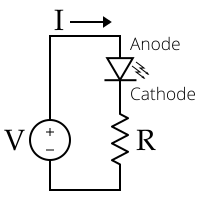
The simplest circuit to drive an LED is through a series resistor. It is commonly used for indicators and digital displays in many consumer appliances. However, this circuit is not energy-efficient, because energy is dissipated in the resistor as heat.
An LED has a voltage drop specified at the intended operating current. Ohm's law and Kirchhoff's circuit laws are used to calculate the appropriate resistor value, by subtracting the LED voltage drop from the supply voltage and dividing by the desired operating current. With a sufficiently high supply voltage, multiple LEDs in series can be powered with one resistor.
If the supply voltage is close or equal to the LED forward voltage, then no reasonable value for the resistor can be calculated, so some other method of current limiting is used.
Power source considerations
The voltage versus current characteristics of an LED are similar to any diode. Current is approximately an exponential function of voltage according to the Shockley diode equation, and a small voltage change may result in a large change in current. If the voltage is below or equal to the threshold no current flows and the result is an unlit LED. If the voltage is too high the current exceeds the maximum rating, overheating and potentially destroying the LED.
As an LED heats up, its voltage drop decreases (band gap decrease[1]). This can encourage the current to increase.
It is therefore important that the power source provides an appropriate current. LEDs should only be connected to constant-current sources.
MOSFET drivers
An active constant current regulator is commonly used for high power LEDs, stabilizing light output over a wide range of input voltages which might increase the useful life of batteries. Active constant current is typically regulated using a depletion-mode MOSFET (metal-oxide-semiconductor field-effect transistor), which is the simplest current limiter.[2] Low drop-out (LDO) constant current regulators also allow the total LED voltage to be a higher fraction of the power supply voltage.
Switched-mode power supplies are used in LED flashlights and household LED lamps. Power MOSFETs are typically used for switching LED drivers, which is an efficient solution to drive high-brightness LEDs. Power integrated circuit (IC) chips such as the Supertex HV9910B are widely used to drive the MOSFETs directly, without the need for additional circuitry.[2] These MOSFET-based Supertex IC chips are the most common LED drivers for solid-state lighting with LED lamps. In 2008, they were used for controlling the solid-state lighting in the Beijing National Aquatics Center during the 2008 Summer Olympics.[3]
Series resistor
Series resistors are a simple way to stabilize the LED current, but energy is wasted in the resistor.
Miniature indicator LEDs are normally driven from low voltage DC via a current-limiting resistor. Currents of 2 mA, 10 mA and 20 mA are common. Sub-mA indicators may be made by driving ultrabright LEDs at very low current. Efficiency tends to reduce at low currents,[4] but indicators running on 100 μA are still practical.
In coin cell powered keyring-type LED lights, the resistance of the cell itself is usually the only current limiting device. The cell should not therefore be replaced with a lower resistance type.
LEDs with built-in series resistors are available. These may save printed circuit board space, and are especially useful when building prototypes or populating a PCB in a way other than its designers intended. However, the resistor value is set at the time of manufacture, removing one of the key methods of setting the LED's intensity.
The value for the series resistance may be obtained from Ohm's law, considering that the supply voltage is offset by the voltage drop across the diode, which varies little over the range of useful currents:

where:
- is resistance in ohms, typically rounded up to the next higher resistor value.

- is the power supply voltage in volts, e.g. 9-volt battery.

- is the LED forward voltage drop across the LED in volts, shown as on LED datasheets. Typically, the forward voltage of an LED is between 1.8 and 3.3 volts. It varies by the color of the LED. A red LED typically drops around 1.7 to 2.0 volts, but since both voltage drop and light frequency increase with band gap, a blue LED may drop around 3 to 3.3 volts.


- is the voltage drop across the switch in volts: (A) for no switch, use 0 volts, (B) for mechanical switch, use 0 volts, (C) for BJT transistor, use collector-emitter saturation voltage from the transistor datasheet.


- is the desired current of the LED in amps. The maximum current is shown on LED datasheets, for example 20 mA (0.020A) is common for many small LEDs. Many circuits operate LEDs at less than the recommended maximum current, to save power, to permit the use of a standard resistor value, or to reduce brightness.

LED arrays


Strings of multiple LEDs are normally connected in series. In one configuration, the source voltage must be greater than or equal to the sum of the individual LED voltages; typically the LED voltages add up to around two-thirds of the supply voltage. A single current-limiting resistor may be used for each string.
Parallel operation is also possible but can be more problematic. Parallel LEDs must have closely matched forward voltages (Vf) in order to have similar branch currents and, therefore, similar light output. Variations in the manufacturing process can make it difficult to obtain satisfactory operation when connecting some types of LEDs in parallel.[5]
LED display
LEDs are often arranged in ways such that each LED (or each string of LEDs) can be individually turned on and off.
Direct drive is the simplest-to-understand approach—it uses many independent single-LED (or single-string) circuits. For example, a person could design a digital clock such that when the clock displays "12:34" on a seven-segment display, the clock would turn on the appropriate segments directly and leave them on until something else needs to be displayed.
However, multiplexed display techniques are more often used than direct drive, because they have lower net hardware costs. For example, most people who design digital clocks design them such that when the clock displays "12:34" on a seven-segment display, at any one instant the clock turns on the appropriate segments of one of the digits—all the other digits are dark. The clock scans through the digits rapidly enough that it gives the illusion that it is "constantly" displaying "12:34" for an entire minute. However, each "on" segment is actually being rapidly pulsed on and off many times a second.
An extension of this technique is Charlieplexing where the ability of some microcontrollers to tri-state their output pins means larger numbers of LEDs can be driven, without using latches. For N pins, it is possible to drive n2-n LEDs.
The use of integrated circuit technology to drive LEDs dates back to the late 1960s. In 1969, Hewlett-Packard introduced the HP Model 5082-7000 Numeric Indicator, an early LED display and the first LED device to use integrated circuit technology. Its development was led by Howard C. Borden, Gerald P. Pighini, and Egyptian engineer Mohamed M. Atalla, at HP Associates and HP Labs, who had engaged in research and development (R&D) on practical LEDs between 1962 and 1968.[6] It was the first intelligent LED display, making it a revolution in digital display technology, replacing the Nixie tube and becoming the basis for later LED displays.[7]
Polarity
Unlike incandescent light bulbs, which illuminate regardless of the electrical polarity, LEDs will only light with correct electrical polarity. When the voltage across the p-n junction is in the correct direction, a significant current flows and the device is said to be forward-biased. If the voltage is of the wrong polarity, the device is said to be reverse biased, very little current flows, and no light is emitted. LEDs can be operated on an alternating current voltage, but they will only light with positive voltage, causing the LED to turn on and off at the frequency of the AC supply.
Most LEDs have low reverse breakdown voltage ratings, so they will also be damaged by an applied reverse voltage above this threshold. The cause of damage is overcurrent resulting from the diode breakdown, not the voltage itself. LEDs driven directly from an AC supply of more than the reverse breakdown voltage may be protected by placing a diode (or another LED) in inverse parallel.
The manufacturer will normally advise how to determine the polarity of the LED in the product datasheet. However, there is no standardization of polarity markings for surface mount devices.[8][9]
Pulsed operation
Many systems pulse LEDs on and off, by applying power periodically or intermittently. So long as the flicker rate is greater than the human flicker fusion threshold, and the LED is stationary relative to the eye, the LED will appear to be continuously lit. Varying the on/off ratio of the pulses is known as pulse-width modulation. In some cases PWM-based drivers are more efficient than constant current or constant voltage drivers.[4][10][11]
Most LED data sheets specify a maximum DC current that is safe for continuous operation. Often they specify some higher maximum pulsed current that is safe for brief pulses, as long as the LED controller keeps the pulse short enough and then turns off the power to the LED long enough for the LED to cool off.
LED as light sensor
In addition to emission, an LED can be used as a photodiode in light detection. This capability may be used in a variety of applications including ambient light detection and bidirectional communications.[12][13][14]
As a photodiode, an LED is sensitive to wavelengths equal to or shorter than the predominant wavelength it emits. For example, a green LED is sensitive to blue light and to some green light, but not to yellow or red light.
This implementation of LEDs may be added to designs with only minor modifications in circuitry.[12] An LED can be multiplexed in such a circuit, such that it can be used for both light emission and sensing at different times.[12][14]
See also
- Joule thief - minimal switch-mode power supply
- Switched-mode power supply applications (SMPS) applications
- Planck–Einstein relation for the relation between band gap and photon frequency
- Shockley diode equation for the relation between forward voltage and current
References
- Van Zeghbroeck, Bart J. (1997). "2.2.5". 2.2.5 Temperature dependence of the energy bandgap. Ece-www.colorado.edu. Retrieved 2009-02-15.
- Winder, Steve (2011). Power Supplies for LED Driving. Newnes. pp. 20–22, 39–41. ISBN 9780080558578.
- "Supertex LED Drivers: The Gold Standard in Driving Solid State Lighting". Electronic Design. Informa. 56 (25–26): 59. 2008.
Supertex's LED driver ICs were selected for controlling the solid state lighting in Beijing's "Water Cube" Aquatic Center.
- Jim Lepkowski, Mike Hoogstra, and Christopher Young. Application note AND8067/D: "NL27WZ04 Dual Gate Inverter Oscillator Increases the Brightness of LEDs While Reducing Power Consumption"
- "Electrical properties of GaN LEDs & Parallel connections" (PDF). Application Note. Nichia. Archived from the original (PDF) on 2007-08-09. Retrieved 2007-08-13.
- Borden, Howard C.; Pighini, Gerald P. (February 1969). "Solid-State Displays" (PDF). Hewlett-Packard Journal: 2–12.
- "Hewlett-Packard 5082-7000". The Vintage Technology Association. Retrieved 15 August 2019.
- "Are There Standards Governing Polarity Marks?". www.circuitinsight.com. Retrieved 19 April 2019.
- "How to Build a PCB: Diode Polarity (No,..." EEWeb Community. Retrieved 19 April 2019.
- Tahan, Mohammad (Winter 2017). "Multiple String LED Driver With Flexible and High-Performance PWM Dimming Control". IEEE Transactions on Power Electronics. 32 (12): 9293–9306. arXiv:2002.00029. Bibcode:2017ITPE...32.9293T. doi:10.1109/TPEL.2017.2655884.
- Dietz, Paul, William Yerazunis, Darren Leigh (2003). "Very Low-Cost Sensing and Communication Using Bidirectional LEDs" (PDF). Mitsubishi Electric Research Laboratories. Archived from the original (PDF) on 2009-02-05. Retrieved 2009-09-07.CS1 maint: multiple names: authors list (link)
- Bent, Sarah, Aoife Moloney and Gerald Farrell (2006). "LEDs as both Optical Sources and Detectors in Bi-directional Plastic Optical Fibre Links". Irish Signals and Systems Conference, 2006. IET: 345.CS1 maint: multiple names: authors list (link)
- Stepniak, G.; Kowalczyk, M.; Maksymiuk, L.; Siuzdak, J. (2015-10-01). "Transmission Beyond 100 Mbit/s Using LED Both as a Transmitter and Receiver". IEEE Photonics Technology Letters. 27 (19): 2067–2070. Bibcode:2015IPTL...27.2067S. doi:10.1109/LPT.2015.2451006. ISSN 1041-1135.