Load cell
A load cell is a type of transducer, specifically a force transducer. It converts a force such as tension, compression, pressure, or torque into an electrical signal that can be measured and standardized. As the force applied to the load cell increases, the electrical signal changes proportionally. The most common types of load cell used are hydraulic, pneumatic, and strain gauge.

Strain gauge load cell
Strain gauge load cells are the kind most often found in industrial settings. It is ideal as it is highly accurate, versatile, and cost-effective. Structurally, a load cell has a metal body to which strain gauges have been secured. The body is usually made of aluminum, alloy steel, or stainless steel which makes it very sturdy but also minimally elastic. This elasticity gives rise to the term "spring element", referring to the body of the load cell. When force is exerted on the load cell, the spring element is slightly deformed, and unless overloaded, always returns to its original shape. As the spring element deforms, the strain gauges also change shape. The resulting alteration to the resistance in the strain gauges can be measured as voltage. The change in voltage is proportional to the amount of force applied to the cell, thus the amount of force can be calculated from the load cell's output.
Strain Gauges

A strain gauge is constructed of very fine wire, or foil, set up in a grid pattern and attached to a flexible backing. When the shape of the strain gauge is altered, a change in its electrical resistance occurs. The wire or foil in the strain gauge is arranged in a way that, when force is applied in one direction, a linear change in resistance results. Tension force stretches a strain gauge, causing it to get thinner and longer, resulting in an increase in resistance. Compression force does the opposite. The strain gauge compresses, becomes thicker and shorter, and resistance decreases. The strain gauge is attached to a flexible backing enabling it to be easily applied to a load cell, mirroring the minute changes to be measured.
Since the change in resistance measured by a single strain gauge is extremely small, it is difficult to accurately measure changes. Increasing the number of strain gauges applied collectively magnifies these small changes into something more measurable. A set of 4 strain gauges set in a specific circuit is called Wheatstone bridge.
Wheatstone Bridge
A Wheatstone bridge is a configuration of four balanced resistors with a known excitation voltage applied as shown below:
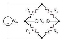
Excitation voltage is a known constant and output voltage is variable depending on the shape of the strain gauges. If all resistors are balanced, meaning then is zero. If the resistance in even one of the resistors changes, then will likewise change. The change in can be measured and interpreted using Ohm's law. Ohm's law states that the current (, measured in amperes) running through a conductor between two points is directly proportional to the voltage across the two points. Resistance (, measured in Ohms) is introduced as the constant in this relationship, independent of the current. Ohm's law is expressed in the equation .


When applied to the 4 legs of the Wheatstone bridge circuit, the resulting equation is:


In a load cell, the resistors are replaced with strain gauges and arranged in alternating tension and compression formation. When force is exerted on the load cell, the structure and resistance of the strain gauges changes and is measured. From the resulting data, can be easily determined using the equation above.[1]
Common types of load cells
There are several types of strain gauge load cells:
- Bending beam: uses strain gauges to monitor the stress in the sensing element when spring element is subjected to a bending forces.[2]
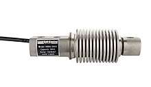 HBBG bending beam load cell (bellows type)
 - Load Button: low-profile load cells often used where the load is concentrated in one single point (button).
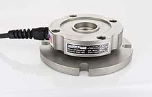
- Pancake: low-profile load cells often used in vessel weighing; can be tension or compression.
- Single point shear beam load cell: spring element fixed at one end and loaded on the other.

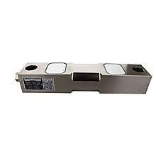
- Double-ended shear beam: spring element fixed at both ends and loaded in the center.
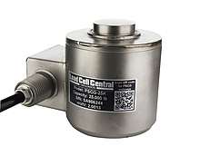
- Canister load cell: Cylindrical shaped spring element; can be used in both tension and compression.
 Canister load cell
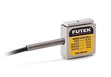
 - S-type load cell: S-shaped spring element; can be used in both compression and tension.
 S-type load cell
 - S-type miniature load cell: similar to the S-shaped load cell, but in smaller geometry (height of only 0.75 inches): [3]
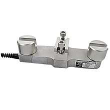
- Wire rope clamps: an assembly attached to a wire rope and measures its tension; commonly used in crane and hoist applications.
- Tension link load cell: often used in crane and hoist weighing systems. Measures tension force only.

- Load pin: replaces pulleys and shivs, typically on cranes.

Pneumatic load cell
The Load cell is designed to automatically regulate the balancing pressure. Air pressure is applied to one end of the diaphragm and it escapes through the nozzle placed at the bottom of the load cell. A pressure gauge is attached with the load cell to measure the pressure inside the cell. The deflection of the diaphragm affects the airflow through the nozzle as well as the pressure inside the chamber.
Hydraulic load cell
The hydraulic load cell uses a conventional piston and cylinder arrangement with the piston placed in a thin elastic diaphragm. The piston doesn't actually come in contact with the load cell. Mechanical stops are placed to prevent over strain of the diaphragm when the loads exceed certain limit. The load cell is completely filled with oil. When the load is applied on the piston, the movement of the piston and the diaphragm results in an increase of oil pressure. This pressure is then transmitted to a hydraulic pressure gauge via a high pressure hose.[5] The gauge's Bourdon tube senses the pressure and registers it on the dial. Because this sensor has no electrical components, it is ideal for use in hazardous areas.[6] Typical hydraulic load cell applications include tank, bin, and hopper weighing.[7] By example, a hydraulic load cell is immune to transient voltages (lightning) so these type of load cells might be a more effective device in outdoor environments. This technology is more expensive than other types of load cells. It is a more costly technology and thus cannot effectively compete on a cost of purchase basis.[8]
Other types
Vibrating load cell
Vibrating wire load cells, which are useful in geomechanical applications due to low amounts of drift, and capacitive load cells where the capacitance of a capacitor changes as the load presses the two plates of a capacitor closer together.
Piezoelectric load cell
Piezoelectric load cells work on the same principle of deformation as the strain gauge load cells, but a voltage output is generated by the basic piezoelectric material – proportional to the deformation of load cell. Useful for dynamic/frequent measurements of force. Most applications for piezo-based load cells are in the dynamic loading conditions, where strain gauge load cells can fail with high dynamic loading cycles. The piezoelectric effect is dynamic, that is, the electrical output of a gauge is an impulse function and is not static. The voltage output is only useful when the strain is changing and does not measure static values.
However, depending on conditioning system used, "quasi static" operation can be done. Using a so-called "Charge amplifier " with "Long" time constant allow accurate measurement lasting many hours for large loads to many minutes for small loads. Another advantage of Piezoelectric load cell, conditioned with a Charge amplifier, is the wide measuring range that can be achieved. Users can choose a load cell with a range of hundred of kN and use it for measuring few N of forces with the same Signal/Noise ratio, again this is possible only with the use of a "Charge amplifier" conditioning.
Common issues
- Mechanical mounting: the cells have to be properly mounted. All the load force has to go through the part of the load cell where its deformation is sensed. Friction may induce offset or hysteresis. Wrong mounting may result in the cell reporting forces along undesired axis, which still may somewhat correlate to the sensed load, confusing the technician.
- Overload: Within its rating, the load cell deforms elastically and returns to its shape after being unloaded. If subjected to loads above its maximum rating, the material of the load cell may plastically deform; this may result in a signal offset, loss of linearity, difficulty with or impossibility of calibration, or even mechanical damage to the sensing element (e.g. delamination, rupture).
- Wiring issues: the wires to the cell may develop high resistance, e.g. due to corrosion. Alternatively, parallel current paths can be formed by ingress of moisture. In both cases the signal develops offset (unless all wires are affected equally) and accuracy is lost.
- Electrical damage: the load cells can be damaged by induced or conducted current. Lightning hitting the construction, or arc welding performed near the cells,[9] can overstress the fine resistors of the strain gauges and cause their damage or destruction. For welding nearby, it is suggested to disconnect the load cell and short all its pins to the ground, nearby the cell itself. High voltages can break through the insulation between the substrate and the strain gauges.
- Nonlinearity: at the low end of their scale, the load cells tend to be nonlinear. This becomes important for cells sensing very large ranges, or with large surplus of load capability to withstand temporary overloads or shocks (e.g. the rope clamps). More points may be needed for the calibration curve.
- Particularity of application: A load cell that is not well suited to the specific magnitude and type of pressure will have poor accuracy, resolution, and reliability.
Excitation and rated output
The bridge is excited with stabilized voltage (usually 10V, but can be 20V, 5V, or less for battery powered instrumentation). The difference voltage proportional to the load then appears on the signal outputs. The cell output is rated in millivolts per volt (mV/V) of the difference voltage at full rated mechanical load. So a 2.96 mV/V load cell will provide 29.6 millivolt signal at full load when excited with 10 volts.
Typical sensitivity values are 1 to 3 mV/V. Typical maximum excitation voltage is around 15 volts.
Wiring
The full-bridge cells come typically in four-wire configuration. The wires to the top and bottom end of the bridge are the excitation (often labelled E+ and E−, or Ex+ and Ex−), the wires to its sides are the signal (labelled S+ and S−). Ideally, the voltage difference between S+ and S− is zero under zero load, and grows proportionally to the load cell's mechanical load.
Sometimes a six-wire configuration is used. The two additional wires are "sense" (Sen+ and Sen−), and are connected to the bridge with the Ex+ and Ex- wires, in a fashion similar to four-terminal sensing. With these additional signals, the controller can compensate for the change in wire resistance due to e.g. temperature fluctuations.
The individual resistors on the bridge usually have resistance of 350 Ω. Sometimes other values (typically 120 Ω, 1,000 Ω) can be encountered.
The bridge is typically electrically insulated from the substrate. The sensing elements are in close proximity and in good mutual thermal contact, to avoid differential signals caused by temperature differences.
Using multiple cells
One or more load cells can be used for sensing a single load.
If the force can be concentrated to a single point (small scale sensing, ropes, tensile loads, point loads), a single cell can be used. For long beams, two cells at the end are used. Vertical cylinders can be measured at three points, rectangular objects usually require four sensors. More sensors are used for large containers or platforms, or very high loads.
If the loads are guaranteed to be symmetrical, some of the load cells can be substituted with pivots. This saves the cost of the load cell but can significantly decrease accuracy.
Load cells can be connected in parallel; in that case, all the corresponding signals are connected together (Ex+ to Ex+, S+ to S+, ...), and the resulting signal is the average of the signals from all the sensing elements. This is often used in e.g. personal scales, or other multipoint weight sensors.
The most common color assignment is red for Ex+, black for Ex−, green for S+, and white for S−.
Less common assignments are red for Ex+, white for Ex−, green for S+, and blue for S−, or red for Ex+, blue for Ex−, green for S+, and yellow for S−.[10] Other values are also possible, e.g. red for Ex+, green for Ex−, yellow for S+ and blue for S−.[11]
Ringing
Every load cell is subject to "ringing" when subjected to abrupt load changes. This stems from the spring-like behavior of load cells. In order to measure the loads, they have to deform. As such, a load cell of finite stiffness must have spring-like behavior, exhibiting vibrations at its natural frequency. An oscillating data pattern can be the result of ringing. Ringing can be suppressed in a limited fashion by passive means. Alternatively, a control system can use an actuator to actively damp out the ringing of a load cell. This method offers better performance at a cost of significant increase in complexity.
Uses
Load cells are used in several types of measuring instruments such as laboratory balances, industrial scales, platform scales[12] and universal testing machines.[13] From 1993 the British Antarctic Survey installed load cells in glass fibre nests to weigh albatross chicks.[14] Load cells are used in a wide variety of items such as the seven-post shaker which is often used to set up race cars.
Load cells weighing performances
Load cells are commonly used to measure weight in an industrial environment. They can be installed on hoppers, reactors...etc... to control their weight capacity, which is often of critical importance for an industrial process. Some performance characteristics of the load cells must be defined and specified to make sure they will cope with the expected service. Among those design characteristics are :
- Combined error
- Minimum verification interval
- Resolution
Load cell specifications
The electrical, physical, and environmental specifications of a load cell help to determine which applications it is appropriate for. Common specifications include:
- Full Scale Output (FSO): Electronic output expressed in mv/V. Measured at full scale.
- Combined Error: % of the full scale output that represents the maximum deviation from the straight line drawn between no load and load at rated capacity. Often measured during decreasing and increasing loads.
- Non-Linearity: The maximum deviation of the calibration curve from a straight line drawn between the rated capacity and zero load. Measured on increasing load and expressed as % of full scale output.
- Hysteresis: Maximum difference between load cell output signals for the same applied load. The first measurement can be obtained by decreasing the load from rated output and the second by increasing the load from zero.
- Repeatability: Maximum difference between output measurements for repeated loads under identical conditions. Measured in % of rated output.
- Zero Balance (Offset): Output reading of the load cell with rated excitation under no load. The deviation in output between a true zero measurement and a real load cell under zero load expressed as a percentage of full scale output.
- Compensated Temperate Range: The temperature range over which a load cell is compensated so that it can ensure zero balance & rated output within specified limits. Expressed as °F or °C.
- Operating Temperature Range: Temperature range extremes in which a load cell can operate without permanent, adverse effects on any of its performance characteristics. Expressed as °F or °C.
- Temperature Effect on Output: Modification of output readings caused by load cell temperature. Expressed as % of full scale output per degree of °F or °C.
- Temperature Effect on Zero: Change in zero balance caused by ambient temperature changes. Expressed as % of full scale output per degree of °F or °C.
- Input Resistance: Input resistance of the load cell's bridge circuit. Measured at the positive & negative excitation leads with no load applied. Measured in Ohms.
- Output Resistance: Output resistance of the load cell's bridge circuit. Measured at the positive & negative excitation leads with no load applied. Measured in Ohms.
- Insulation Resistance: The resistance measured along pathways between the: bridge circuit and transducer element, bridge circuit and the cable shield, and the transducer element and the cable shield. Typically measured at fifty volts under standard test conditions.
- Recommended Excitation: Maximum recommended excitation voltage of the transducer for it to operate within its specifications. Expressed in VDC.
- Cable Length: Length of the standard cable for which the load cell is calibrated. Cable length affects how the load cell is calibrated.
- Safe Overload: The maximum load that can be applied to a load cell without causing permanent effects to its performance specifications. Measured as a % of full scale output.
- Ultimate Overload: Maximum load that can be withstood without causing structural failure.
- Material: Substance that comprises the spring element of the load cell.
Load cell calibration
Load cells are an integral part of most weighing systems in industrial, aerospace and automotive industries, enduring rigorous daily use. Over time, load cells will drift, age and misalign; therefore, they will need to be calibrated regularly to ensure accurate results are maintained.[16] ISO9000 and most other standards specify a maximum period of around 18 months to 2 years between re-calibration procedures, dependent on the level of load cell deterioration. Annual re-calibration is considered best practice by many load cell users for ensuring the most accurate measurements.
Standard calibration tests will use linearity and repeatability as a calibration guideline as these are both used to determine accuracy. Calibration is conducted incrementally starting working in ascending or descending order. For example, in the case of a 60 tonne load cell, then specific test weights that measure in 5, 10, 20, 40 and 60 tonne increments may be used – A five step calibration process is usually sufficient for ensuring a device is accurately calibrated. Repeating this five-step calibration procedure 2-3 times is recommended for consistent results.[17]
See also
References
- "Load Cell and Strain Gauge Basics | Load Cell Central". www.800loadcel.com. Retrieved 2019-07-29.
- "how sensors work - load cells". www.sensorland.com. Retrieved 2019-07-29.
- "Miniature S-Beam Load Cells". www.FUTEK.com. Retrieved 2020-05-04.
- "Load Cell Types and Uses". www.800loadcel.com. Retrieved 2019-07-29.
- DeGlandon, Kathy. "Selectring the Best Hydraulic Pressure Sensor". Drilling Instruments. Drilling Instruments. Retrieved 28 December 2016.
- http://www.cardinalscale.com/wp-content/uploads/2012/04/Hydraulic-Load-Cell-Advantages.pdf
- "Load Cells – Hydraulic". www.centralcarolinascale.com. Retrieved 2018-03-15.
- "Emery Winslow Scale Company – Industrial Scales – Hydrostatic Load Cells For Harsh Environments". www.emerywinslow.com. Retrieved 2018-03-15.
- https://powderprocess.net/Equipments%5B%5D html/Load_cells.html
- http://www.aicpl.com/brochures/loadapp.pdf
- http://www.s-e-g.com/documents/Load%20Cells/Type%20K/F31-16E.PDF
- "2. Where are load cells used? 【Introduction to Load Cells】 A&D". www.aandd.jp. Retrieved 2018-03-15.
- "Load cell testing gets straight to the point". Maritime Journal. Mercator Media. 20 December 2010. Archived from the original on 7 April 2011.
- Highfield, Roger. Antarctic's birds thrive on warmth, The Daily Telegraph 18 August 1993
- "Understanding Load Cell Specifications". www.800loadcel.com. Retrieved 2019-08-06.
- "Control of Monitoring & Measuring Equipment". www.iso-9001-checklist.co.uk. Retrieved 2018-07-17.
- "Load Cells: A Beginner's Guide – Measurement Shop UK". www.measurementshop.co.uk. Retrieved 2018-07-17.
Standards
- ASTM E4 – Practices for Force Verification of Testing Machines
- ASTM E74 – Practice for Calibration of Force Measuring Instruments for Verifying the Force Indication of Testing Machines
- NTEP – National Conference on Weights and Measures (Certificate of Conformance)