Photoelasticity
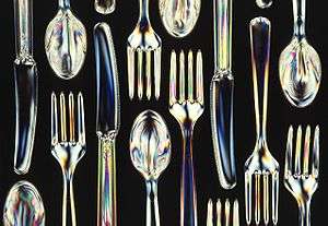
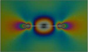
Photoelasticity describes changes in the optical properties of a material under mechanical deformation. It is a property of all dielectric media and is often used to experimentally determine the stress distribution in a material, where it gives a picture of stress distributions around discontinuities in materials. Photoelastic experiments (also informally referred to as photoelasticity) are an important tool for determining critical stress points in a material, and are used for determining stress concentration in irregular geometries.
History
The photoelastic phenomenon was first discovered by the Scottish physicist David Brewster.[1][2] Experimental frameworks were developed at the beginning of the twentieth century with the works of E. G. Coker and L. N. G. Filon of University of London. Their book Treatise on Photoelasticity, published in 1930 by Cambridge Press, became a standard text on the subject. Between 1930 and 1940, many other books appeared on the subject, including books in Russian, German and French. At the same time, much development occurred in the field – great improvements were achieved in technique, and the equipment was simplified. With refinements in the technology, photoelastic experiments were extended to determining three-dimensional states of stress. In parallel to developments in experimental technique, the first phenomenological description of photoelasticity was given in 1890 by Friedrich Pockels,[3] however this was proved inadequate almost a century later by Nelson & Lax[4] as the description by Pockels only considered the effect of mechanical strain on the optical properties of the material.
With the advent of the digital polariscope – made possible by light-emitting diodes – continuous monitoring of structures under load became possible. This led to the development of dynamic photoelasticity, which has contributed greatly to the study of complex phenomena such as fracture of materials.
Applications
Photoelasticity has been used for a variety of stress analyses and even for routine use in design, particularly before the advent of numerical methods, such as finite elements or boundary elements.[5] Digitization of polariscopy enables fast image acquisition and data processing, which allows its industrial applications to control quality of manufacturing process for materials such as glass[6] and polymer.[7] Dentistry utilizes photoelasticity to analyze strain in denture materials.[8]
Photoelasticity can successfully be used to investigate the highly localized stress state within masonry[9][10][11] or in proximity of a rigid line inclusion (stiffener) embedded in an elastic medium.[12] In the former case, the problem is nonlinear due to the contacts between bricks, while in the latter case the elastic solution is singular, so that numerical methods may fail to provide correct results. These can be obtained through photoelastic techniques. Dynamic photoelasticity integrated with high-speed photography is utilized to investigate fracture behavior in materials.[13] Another important application of the photoelasticity experiments is to study the stress field around bi-material notches.[14] Bi-material notches exist in many engineering application like welded or adhesively bonded structures
Formal definition
For a linear dielectric material the change in the inverse permittivity tensor with respect to the deformation (the gradient of the displacement ) is described by [15]


where is the fourth-rank photoelasticity tensor, is the linear displacement from equilibrium, and denotes differentiation with respect to the Cartesian coordinate . For isotropic materials, this definition simplifies to [16]


where is the symmetric part of the photoelastic tensor (the photoelastic strain tensor), and is the linear strain. The antisymmetric part of is known as the roto-optic tensor. From either definition, it is clear that deformations to the body may induce optical anisotropy, which can cause an otherwise optically isotropic material to exhibit birefringence. Although the symmetric photoelastic tensor is most commonly defined with respect to mechanical strain, it is also possible to express photoelasticity in terms of the mechanical stress.


Experimental principles
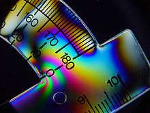
The experimental procedure relies on the property of birefringence, as exhibited by certain transparent materials. Birefringence is a phenomenon in which a ray of light passing through a given material experiences two refractive indices. The property of birefringence (or double refraction) is observed in many optical crystals. Upon the application of stresses, photoelastic materials exhibit the property of birefringence, and the magnitude of the refractive indices at each point in the material is directly related to the state of stresses at that point. Information such as maximum shear stress and its orientation are available by analyzing the birefringence with an instrument called a polariscope.
When a ray of light passes through a photoelastic material, its electromagnetic wave components are resolved along the two principal stress directions and each component experiences a different refractive index due to the birefringence. The difference in the refractive indices leads to a relative phase retardation between the two components. Assuming a thin specimen made of isotropic materials, where two-dimensional photoelasticity is applicable, the magnitude of the relative retardation is given by the stress-optic law:[17]

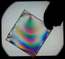
where Δ is the induced retardation, C is the stress-optic coefficient, t is the specimen thickness, λ is the vacuum wavelength, and σ1 and σ2 are the first and second principal stresses, respectively. The retardation changes the polarization of transmitted light. The polariscope combines the different polarization states of light waves before and after passing the specimen. Due to optical interference of the two waves, a fringe pattern is revealed. The number of fringe order N is denoted as

which depends on relative retardation. By studying the fringe pattern one can determine the state of stress at various points in the material.
For materials that do not show photoelastic behavior, it is still possible to study the stress distribution. The first step is to build a model, using photoelastic materials, which has geometry similar to the real structure under investigation. The loading is then applied in the same way to ensure that the stress distribution in the model is similar to the stress in the real structure.
Isoclinics and isochromatics
Isoclinics are the loci of the points in the specimen along which the principal stresses are in the same direction.
Isochromatics are the loci of the points along which the difference in the first and second principal stress remains the same. Thus they are the lines which join the points with equal maximum shear stress magnitude.[18]
Two-dimensional photoelasticity
Photoelasticity can describe both three-dimensional and two-dimensional states of stress. However, examining photoelasticity in three-dimensional systems is more involved than two-dimensional or plane-stress system. So the present section deals with photoelasticity in a plane stress system. This condition is achieved when the thickness of the prototype is much smaller as compared to dimensions in the plane. Thus one is only concerned with stresses acting parallel to the plane of the model, as other stress components are zero. The experimental setup varies from experiment to experiment. The two basic kinds of setup used are plane polariscope and circular polariscope.
The working principle of a two-dimensional experiment allows the measurement of retardation, which can be converted to the difference between the first and second principal stress and their orientation. To further get values of each stress component, a technique called stress-separation is required.[19] Several theoretical and experimental methods are utilized to provide additional information to solve individual stress components.
Plane polariscope setup
The setup consists of two linear polarizers and a light source. The light source can either emit monochromatic light or white light depending upon the experiment. First the light is passed through the first polarizer which converts the light into plane polarized light. The apparatus is set up in such a way that this plane polarized light then passes through the stressed specimen. This light then follows, at each point of the specimen, the direction of principal stress at that point. The light is then made to pass through the analyzer and we finally get the fringe pattern.
The fringe pattern in a plane polariscope setup consists of both the isochromatics and the isoclinics. The isoclinics change with the orientation of the polariscope while there is no change in the isochromatics.
The same device functions as a plane polariscope when quarter wave plates are taken aside or rotated so their axes parallel to polarization axes
Circular polariscope setup
In a circular polariscope setup two quarter-wave plates are added to the experimental setup of the plane polariscope. The first quarter-wave plate is placed in between the polarizer and the specimen and the second quarter-wave plate is placed between the specimen and the analyzer. The effect of adding the quarter-wave plate after the source-side polarizer is that we get circularly polarized light passing through the sample. The analyzer-side quarter-wave plate converts the circular polarization state back to linear before the light passes through the analyzer.
The basic advantage of a circular polariscope over a plane polariscope is that in a circular polariscope setup we only get the isochromatics and not the isoclinics. This eliminates the problem of differentiating between the isoclinics and the isochromatics.
See also
References
- D. Brewster, Experiments on the depolarization of light as exhibited by various mineral, animal and vegetable bodies with a reference of the phenomena to the general principle of polarization, Phil. Tras. 1815, pp. 29–53.
- D. Brewster, On the communication of the structure of doubly-refracting crystals to glass, murite of soda, flour spar, and other substances by mechanical compression and dilation, Phil. Tras. 1816, pp. 156–178.
- Pockels, F. Ueber die durch einseitigen Druck hervorgerufene Doppelbrechung regulärer Krystalle, speciell von Steinsalz und Sylvin, Annalen der Physik, 275, 1890, 440.
- Nelson, D.F., and Lax, M. New Symmetry for Acousto-Optic Scattering, Physical Review Letters, 1970, 24:8, 379-380.
- Frocht, M.M., Photoelasticity. J. Wiley and Sons, London, 1965
- Ajovalasit, A., Petrucci, G., Scafidi, M., RGB photoelasticity applied to the analysis of membrane residual stress in glass, Measurement Science and Technology, 2012, 23-2, no. 025601
- Kramer, S., Beiermann, B., Davis, D., Sottos, N., White, S., Moore, J., Characterization of mechanochemically active polymers using combined photoelasticity and fluorescence measurements, SEM Annual Conference and Exposition on Experimental and Applied Mechanics, 2010, 2, pp. 896–907.
- Fernandes, C. P., Glantz, P.-O. J., Svensson, S. A., Bergmark, A. Reflection photoelasticity: A new method for studies of clinical mechanics in prosthetic dentistry Dental Materials, 2003, 19-2, pp. 106–117.
- D. Bigoni and G. Noselli, Localized stress percolation through dry masonry walls. Part I – Experiments. European Journal of Mechanics A/Solids, 2010, 29, 291–298.
- D. Bigoni and G. Noselli, Localized stress percolation through dry masonry walls. Part II – Modelling. European Journal of Mechanics A/Solids, 2010, 29, pp. 299–307.
- Bigoni, D. Nonlinear Solid Mechanics: Bifurcation Theory and Material Instability. Cambridge University Press, 2012 . ISBN 9781107025417.
- G. Noselli, F. Dal Corso and D. Bigoni, The stress intensity near a stiffener disclosed by photoelasticity. International Journal of Fracture, 2010, 166, 91–103.
- Shukla, A., High-speed fracture studies on bimaterial interfaces using photoelasticity – A review, Journal of Strain Analysis for Engineering Design, 2012, 36-2, 119–142.
- Ayatollahi, M. R., Mirsayar, M. M., Dehghany, M., Experimental determination of stress field parameters in bi-material notches using photoelasticity, "Materials & Design," 2011, 32, 4901–4908.
- J. F. Nye, "Physical Properties of Crystals: Their Representation by Tensors and Matrices", Oxford University Press, 1957.
- R. E. Newnham, "Properties of Materials: Anisotropy, Symmetry, Structure", Oxford University Press, 2005.
- Dally, J.W. and Riley, W.F., Experimental Stress Analysis, 3rd edition, McGraw-Hill Inc., 1991
- Ramesh, K., Digital Photoelasticity, Springer, 2000
- Fernandez M.S-B., Calderon, J. M. A., Diez, P. M. B. and Segura, I. I. C., Stress-separation techniques in photoelasticity: A review. The Journal of Strain Analysis for Engineering Design, 2010, 45:1 [doi:10.1243/03093247JSA583]