Wheatstone bridge
A Wheatstone bridge is an electrical circuit used to measure an unknown electrical resistance by balancing two legs of a bridge circuit, one leg of which includes the unknown component. The primary benefit of the circuit is its ability to provide extremely accurate measurements (in contrast with something like a simple voltage divider).[1] Its operation is similar to the original potentiometer.
The Wheatstone bridge was invented by Samuel Hunter Christie (sometimes spelled "Christy") in 1833 and improved and popularized by Sir Charles Wheatstone in 1843. One of the Wheatstone bridge's initial uses was for soils analysis and comparison.[2].
Operation
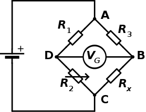
In the figure, is the fixed, yet unknown, resistance to be measured.

and are resistors of known resistance and the resistance of is adjustable. The resistance is adjusted until the bridge is "balanced" and no current flows through the galvanometer . At this point, the voltage between the two midpoints (B and D) will be zero. Therefore the ratio of the two resistances in the known leg is equal to the ratio of the two resistances in the unknown leg . If the bridge is unbalanced, the direction of the current indicates whether is too high or too low.


At the point of balance,

Detecting zero current with a galvanometer can be done to extremely high precision. Therefore, if and are known to high precision, then can be measured to high precision. Very small changes in disrupt the balance and are readily detected.
Alternatively, if and are known, but is not adjustable, the voltage difference across or current flow through the meter can be used to calculate the value of using Kirchhoff's circuit laws. This setup is frequently used in strain gauge and resistance thermometer measurements, as it is usually faster to read a voltage level off a meter than to adjust a resistance to zero the voltage.

Derivation

Quick derivation at balance
At the point of balance, both the voltage and the current between the two midpoints (B and D) are zero. Therefore, , , , and:


Full derivation using Kirchhoff's circuit laws
First, Kirchhoff's first law is used to find the currents in junctions B and D:

Then, Kirchhoff's second law is used for finding the voltage in the loops ABD and BCD:

When the bridge is balanced, then IG = 0, so the second set of equations can be rewritten as:

Then, equation (1) is divided by equation (2) and the resulting equation is rearranged, giving:

Due to: I3 = Ix and I1 = I2 being proportional from Kirchhoff's First Law in the above equation I3 I2 over I1 Ix cancel out of the above equation. The desired value of Rx is now known to be given as:

On the other hand, if the resistance of the galvanometer is high enough that IG is negligible, it is possible to compute Rx from the three other resistor values and the supply voltage (VS), or the supply voltage from all four resistor values. To do so, one has to work out the voltage from each potential divider and subtract one from the other. The equations for this are:

where VG is the voltage of node D relative to node B.
Significance
The Wheatstone bridge illustrates the concept of a difference measurement, which can be extremely accurate. Variations on the Wheatstone bridge can be used to measure capacitance, inductance, impedance and other quantities, such as the amount of combustible gases in a sample, with an explosimeter. The Kelvin bridge was specially adapted from the Wheatstone bridge for measuring very low resistances. In many cases, the significance of measuring the unknown resistance is related to measuring the impact of some physical phenomenon (such as force, temperature, pressure, etc.) which thereby allows the use of Wheatstone bridge in measuring those elements indirectly.
The concept was extended to alternating current measurements by James Clerk Maxwell in 1865 and further improved as Blumlein bridge by Alan Blumlein around 1926.
Modifications of the fundamental bridge

The Wheatstone bridge is the fundamental bridge, but there are other modifications that can be made to measure various kinds of resistances when the fundamental Wheatstone bridge is not suitable. Some of the modifications are:
- Carey Foster bridge, for measuring small resistances
- Kelvin bridge, for measuring small four-terminal resistances
- Maxwell bridge, and Wien bridge for measuring reactive components.
See also
- Diode bridge, product mixer – diode bridges
- Phantom circuit – a circuit using a balanced bridge
- Post office box (electricity)
- Potentiometer (measuring instrument)
- Potential divider
- Ohmmeter
- Resistance thermometer
- Strain gauge
References
- "Circuits in Practice: The Wheatstone Bridge, What It Does, and Why It Matters", as discussed in this MIT ES.333 class video
- "The Genesis of the Wheatstone Bridge" by Stig Ekelof discusses Christie's and Wheatstone's contributions, and why the bridge carries Wheatstone's name. Published in "Engineering Science and Education Journal", volume 10, no 1, February 2001, pages 37–40.
External links
- DC Metering Circuits chapter from Lessons In Electric Circuits Vol 1 DC free ebook and Lessons In Electric Circuits series.
- Test Set I-49