Pressure sensor
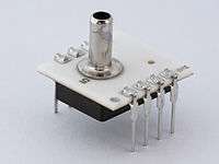
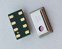
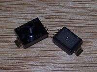
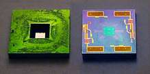
A pressure sensor is a device for pressure measurement of gases or liquids. Pressure is an expression of the force required to stop a fluid from expanding, and is usually stated in terms of force per unit area. A pressure sensor usually acts as a transducer; it generates a signal as a function of the pressure imposed. For the purposes of this article, such a signal is electrical.


Pressure sensors are used for control and monitoring in thousands of everyday applications. Pressure sensors can also be used to indirectly measure other variables such as fluid/gas flow, speed, water level, and altitude. Pressure sensors can alternatively be called pressure transducers, pressure transmitters, pressure senders, pressure indicators, piezometers and manometers, among other names.
Pressure sensors can vary drastically in technology, design, performance, application suitability and cost. A conservative estimate would be that there may be over 50 technologies and at least 300 companies making pressure sensors worldwide.
There is also a category of pressure sensors that are designed to measure in a dynamic mode for capturing very high speed changes in pressure. Example applications for this type of sensor would be in the measuring of combustion pressure in an engine cylinder or in a gas turbine. These sensors are commonly manufactured out of piezoelectric materials such as quartz.
Some pressure sensors are pressure switches, which turn on or off at a particular pressure. For example, a water pump can be controlled by a pressure switch so that it starts when water is released from the system, reducing the pressure in a reservoir.
Types of pressure measurements

Pressure sensors can be classified in terms of pressure ranges they measure, temperature ranges of operation, and most importantly the type of pressure they measure. Pressure sensors are variously named according to their purpose, but the same technology may be used under different names.
- Absolute pressure sensor
This sensor measures the pressure relative to perfect vacuum.
- Gauge pressure sensor
This sensor measures the pressure relative to atmospheric pressure. A tire pressure gauge is an example of gauge pressure measurement; when it indicates zero, then the pressure it is measuring is the same as the ambient pressure.
- Vacuum pressure sensor
This term can cause confusion. It may be used to describe a sensor that measures pressures below atmospheric pressure, showing the difference between that low pressure and atmospheric pressure, but it may also be used to describe a sensor that measures absolute pressure relative to a vacuum.
- Differential pressure sensor
This sensor measures the difference between two pressures, one connected to each side of the sensor. Differential pressure sensors are used to measure many properties, such as pressure drops across oil filters or air filters, fluid levels (by comparing the pressure above and below the liquid) or flow rates (by measuring the change in pressure across a restriction). Technically speaking, most pressure sensors are really differential pressure sensors; for example a gauge pressure sensor is merely a differential pressure sensor in which one side is open to the ambient atmosphere.
- Sealed pressure sensor
This sensor is similar to a gauge pressure sensor except that it measures pressure relative to some fixed pressure rather than the ambient atmospheric pressure (which varies according to the location and the weather).
Pressure-sensing technology

There are two basic categories of analog pressure sensors,
Force collector types These types of electronic pressure sensors generally use a force collector (such a diaphragm, piston, bourdon tube, or bellows) to measure strain (or deflection) due to applied force over an area (pressure).
- Piezoresistive strain gauge
Uses the piezoresistive effect of bonded or formed strain gauges to detect strain due to applied pressure, resistance increasing as pressure deforms the material. Common technology types are Silicon (Monocrystalline), Polysilicon Thin Film, Bonded Metal Foil, Thick Film, Silicon-on-Sapphire and Sputtered Thin Film. Generally, the strain gauges are connected to form a Wheatstone bridge circuit to maximize the output of the sensor and to reduce sensitivity to errors. This is the most commonly employed sensing technology for general purpose pressure measurement.
- Capacitive
Uses a diaphragm and pressure cavity to create a variable capacitor to detect strain due to applied pressure, capacitance decreasing as pressure deforms the diaphragm. Common technologies use metal, ceramic, and silicon diaphragms.
- Electromagnetic
Measures the displacement of a diaphragm by means of changes in inductance (reluctance), LVDT, Hall Effect, or by eddy current principle.
- Piezoelectric
Uses the piezoelectric effect in certain materials such as quartz to measure the strain upon the sensing mechanism due to pressure. This technology is commonly employed for the measurement of highly dynamic pressures. As the basic principle is dynamic no static pressures can be measured with piezoelectric sensors.
- Strain-Gauge
Strain gauge based pressure sensors also use a pressure sensitive element where metal strain gauges are glued on or thin film gauges are applied on by sputtering. This measuring element can either be a diaphragm or for metal foil gauges measuring bodies in can-type can also be used. The big advantages of this monolithic can-type design are an improved rigidity and the capability to measure highest pressures of up to 15,000 bar. The electrical connection is normally done via a Wheatstone bridge which allows for a good amplification of the signal and precise and constant measuring results.[1]
- Optical
Techniques include the use of the physical change of an optical fiber to detect strain due to applied pressure. A common example of this type utilizes Fiber Bragg Gratings. This technology is employed in challenging applications where the measurement may be highly remote, under high temperature, or may benefit from technologies inherently immune to electromagnetic interference. Another analogous technique utilizes an elastic film constructed in layers that can change reflected wavelengths according to the applied pressure (strain).[2]
- Potentiometric
Uses the motion of a wiper along a resistive mechanism to detect the strain caused by applied pressure.
- Force balancing
.jpg)
Force-balanced fused quartz bourdon tubes use a spiral bourdon tube to exert force on a pivoting armature containing a mirror, the reflection of a beam of light from the mirror senses the angular displacement and current is applied to electromagnets on the armature to balance the force from the tube and bring the angular displacement to zero, the current that is applied to the coils is used as the measurement. Due to the extremely stable and repeatable mechanical and thermal properties of fused quartz and the force balancing which eliminates most non-linear effects these sensors can be accurate to around 1PPM of full scale.[3] Due to the extremely fine fused quartz structures which are made by hand and require expert skill to construct these sensors are generally limited to scientific and calibration purposes. Non force-balancing sensors have lower accuracy and reading the angular displacement cannot be done with the same precision as a force-balancing measurement, although easier to construct due to the larger size these are no longer used.
Other types
These types of electronic pressure sensors use other properties (such as density) to infer pressure of a gas, or liquid.
- Resonant
Uses the changes in resonant frequency in a sensing mechanism to measure stress, or changes in gas density, caused by applied pressure. This technology may be used in conjunction with a force collector, such as those in the category above. Alternatively, resonant technology may be employed by exposing the resonating element itself to the media, whereby the resonant frequency is dependent upon the density of the media. Sensors have been made out of vibrating wire, vibrating cylinders, quartz, and silicon MEMS. Generally, this technology is considered to provide very stable readings over time.
A pressure sensor, a resonant quartz crystal strain gauge with a bourdon tube force collector is the critical sensor of DART.[4] DART detects tsunami waves from the bottom of the open ocean. It has a pressure resolution of approximately 1mm of water when measuring pressure at a depth of several kilometers.[5]
- Thermal
Uses the changes in thermal conductivity of a gas due to density changes to measure pressure. A common example of this type is the Pirani gauge.
- Ionization
Measures the flow of charged gas particles (ions) which varies due to density changes to measure pressure. Common examples are the Hot and Cold Cathode gauges.
Applications
There are many applications for pressure sensors:
- Pressure sensing
This is where the measurement of interest is pressure, expressed as a force per unit area. This is useful in weather instrumentation, aircraft, automobiles, and any other machinery that has pressure functionality implemented.
- Altitude sensing
This is useful in aircraft, rockets, satellites, weather balloons, and many other applications. All these applications make use of the relationship between changes in pressure relative to the altitude. This relationship is governed by the following equation:[6]
This equation is calibrated for an altimeter, up to 36,090 feet (11,000 m). Outside that range, an error will be introduced which can be calculated differently for each different pressure sensor. These error calculations will factor in the error introduced by the change in temperature as we go up.
Barometric pressure sensors can have an altitude resolution of less than 1 meter, which is significantly better than GPS systems (about 20 meters altitude resolution). In navigation applications altimeters are used to distinguish between stacked road levels for car navigation and floor levels in buildings for pedestrian navigation.
- Flow sensing
This is the use of pressure sensors in conjunction with the venturi effect to measure flow. Differential pressure is measured between two segments of a venturi tube that have a different aperture. The pressure difference between the two segments is directly proportional to the flow rate through the venturi tube. A low pressure sensor is almost always required as the pressure difference is relatively small.
- Level / depth sensing
A pressure sensor may also be used to calculate the level of a fluid. This technique is commonly employed to measure the depth of a submerged body (such as a diver or submarine), or level of contents in a tank (such as in a water tower). For most practical purposes, fluid level is directly proportional to pressure. In the case of fresh water where the contents are under atmospheric pressure, 1psi = 27.7 inH20 / 1Pa = 9.81 mmH20. The basic equation for such a measurement is
where P = pressure, ρ = density of the fluid, g = standard gravity, h = height of fluid column above pressure sensor
- Leak testing
A pressure sensor may be used to sense the decay of pressure due to a system leak. This is commonly done by either comparison to a known leak using differential pressure, or by means of utilizing the pressure sensor to measure pressure change over time.
Ratiometric correction of transducer output
Piezoresistive transducers configured as Wheatstone bridges often exhibit ratiometric behavior with respect not only to the measured pressure, but also the transducer supply voltage.
where:
is the output voltage of the transducer.
is the actual measured pressure.
is the nominal transducer scale factor (given an ideal transducer supply voltage) in units of voltage per pressure.
is the actual transducer supply voltage.
is the ideal transducer supply voltage.
Correcting measurements from transducers exhibiting this behavior requires measuring the actual transducer supply voltage as well as the output voltage and applying the inverse transform of this behavior to the output signal:
Note: Common mode signals often present in transducers configured as Wheatstone bridges are not considered in this analysis.
See also
- Altimeter
- Atmospheric pressure
- Barometer
- Brake fluid pressure sensor
- Dynamic pressure
- List of MOSFET applications
- List of sensors
- MAP sensor
- MOSFET
- Pressure
References
- "What is a Pressure Sensor?". HBM. Retrieved 2018-05-09.
- Elastic hologram' pages 113-117, Proc. of the IGC 2010, ISBN 978-0-9566139-1-2 here: http://www.dspace.cam.ac.uk/handle/1810/225960
- [https://www.researchgate.net/publication/230966593_Characterization_of_quartz_Bourdon-type_high-pressure_transducers
- Milburn, Hugh. "The NOAA DART II Description and Disclosure" (PDF). noaa.gov. NOAA, U.S. Government. Retrieved 4 April 2020.
- Eble, M. C.; Gonzalez, F. I. "Deep-Ocean Bottom Pressure Measurements in the Northeast Pacific" (PDF). noaa.gov. NOAA, U.S. Government. Retrieved 4 April 2020.
- http://www.wrh.noaa.gov/slc/projects/wxcalc/formulas/pressureAltitude.pdf Archived 2017-07-03 at the Wayback Machine National Oceanic and Atmospheric Association
| Wikimedia Commons has media related to Pressure sensors. |