List of vacuum tubes
This is a list of vacuum tubes or thermionic valves, and low-pressure gas-filled tubes, or discharge tubes. Before the advent of semiconductor devices, thousands of tube types were used in consumer electronics. Many industrial, military or otherwise professional tubes were also produced. Only a few types are still used today, mainly in high-power, high-frequency applications.
Heater or filament ratings
Receiving tubes have heaters or filaments intended for direct battery operation, parallel operation off a dedicated winding on a supply transformer, or series string operation on transformer-less sets. High-power RF power tubes are directly heated; the heater voltage must be much smaller than the signal voltage on the grid and is therefore in the 5...25 V range, drawing up to hundreds of amperes from a suitable heater transformer. In some valve part number series, the voltage class of the heater is given in the part number, and a similar valve might be available with several different heater voltage ratings.
Tube bases and envelopes
Abbreviations used in this list
- ST – Shouldered tube
- GT – Glass tube
- MT – Miniature tube, such as Noval B9A or Miniature 7-pin B7G
- FL – Subminiature all-glass elliptical body and flat bases with long, inline "flying leads" (pigtails) that are soldered into the circuit
- SL – Subminiature all-glass elliptical body and flat bases with short inline leads that can be soldered or can be mated with a special socket. (Flying leads can be cut short to fit into inline sockets.)
- R8 – Subminiature all-glass round body and base with 8 flying leads or stiff pins arranged in a circle
Numbering systems
North American systems
RMA system (1942)
The system assigned numbers with the base form "1A21", and is therefore also referred to as the "1A21 system".[1] The first numeric character indicated the filament/heater power rating, the second alphabetic character was a code for the function, and the last 2 digits were sequentially assigned, beginning with 21
RMA tubes
- 1B23 – 20 kW, 400 to 1500 MHz Gas-filled, cold-cathode Transmit/Receive Tube (TR cell)
- 1B41 – Gas-filled, cold-cathode 9.5 kV, 450 A spark gap
- 1B45 – Gas-filled, cold-cathode 14 kV, 450 A spark gap
- 1B49 – Gas-filled, cold-cathode 12 kV, 450 A spark gap
- 1C21 – Gas-filled, 25 mAavg, 100 mApeak, triode thyratron
- 1D21 – Strobotron Gas-filled, 50 mAavg, 5 Apeak, luminiscent tetrode thyratron for use as a stroboscope lamp
- 1P21 – 9-stage Photomultiplier, spectral S4 response, 11-pin base
- 1P25 – Infrared image converter used in World War II night vision "sniperscopes".
- 1P29 – Gas-filled phototube, spectral S3 response, 4-pin base
- 1P39 – Vacuum Phototube, spectral S4 response, 4-pin base
- 1S22 – 10 kV, 20 A Vacuum SPDT switch
- 2C21 – Dual transmitting triode, indirectly heated, 7-pin base plus a single top cap for one of the grids
- 2C22 – Transmitting triode, indirectly heated, 8-pin base plus dual top cap for grid and anode
- 2C36 – Rocket-type disk-seal UHF triode with an internal feedback circuit between cathode and anode, for use as UHF oscillator up to 1.75 GHz
- 2C37 – Rocket triode for use as SHF oscillator up to 3.3 GHz
- 2C39A – Oil can-type disk-seal UHF power triode with glass spacers up to 3 GHz, Panode = 100 W
- 2C39B – 2C39A with ceramic spacers
- 2C40 – Lighthouse-type disk-seal UHF power triode for continuous operation, Panode = 6.5 W at 3370 MHz
- 2C41 – Oil can UHF power triode for pulsed operation, 2200 Wpeak at 3 GHz
- 2C42 – Lighthouse UHF power triode for pulsed operation, 1750 Wpeak at 1050 MHz; improved 446
- 2C43 – Lighthouse UHF power triode, indirectly heated, up to 3.37 GHz, 6-pin base
- 2C46 – Lighthouse UHF power triode
- 2C51 – Dual shielded triode, indirectly heated, 9-pin base
- 2D21/EN91 (PL21, PL2D21, CV797) – 100 mAavg, 500 mApeak, 10 Asurge, Gas-filled, indirectly heated tetrode thyratron, negative starter voltage, miniature 7-pin base, for relay and grid-controlled rectifier service, used in jukeboxes and computer equipment.
- 2E22 – 53 W Power pentode, 5-pin base with anode on top cap
- 2E26 – Popular amateur 5.3 W VHF beam power tetrode up to 175 MHz, octal base
- 2E30 – 10 W Directly heated beam power tetrode with deflection screens available on separate pin, miniature 7-pin base
- 2E31 – Subminiature, directly heated, fully shielded sharp-cutoff RF/IF pentode, 5-pin all-glass pigtailed, FL
- 2E32 – Similar to 2E31, SL
- 2E35 – 6 mW Subminiature directly heated power pentode, 5-pin all-glass pigtailed, FL
- 2E36 – Similar to 2E35, SL
- 2E41 – Diode, pentode, FL
- 2E42 – Similar to 2E42, SL
- 2F21 – Indirectly heated hexode monoscope, Indian Head test pattern, 6-pin base with dual top caps for grid4 and anode
- 2G21 – Directly heated triode-heptode mixer, 7-pin all-glass pigtailed
- 2G41 – Triode-heptode converter, FL
- 2G42 – Similar to type 2G42, SL
- 2H21 – Phasitron, a magnetically controlled beam-deflection phase modulator tube[2] similar to the 5593, used in early FM broadcast transmitters[3][4][5]
- 2J30 to 2J34 – 300 kW S-band Magnetrons
- 2J55 and 2J56 – 40 kW X-band Magnetrons for use as pulsed oscillator
- 2K25 – 25 mW 8.5 to 9.66 GHz reflex Klystron
- 2K50 – 15 mW 23.5 to 24.5 GHz reflex Klystron
- 2P23 – Early image orthicon TV camera tube.
- 3B28 – Xenon half wave rectifier; ruggedized replacement for mercury vapor type 866.
- 3C22 – Disk-seal UHF power triode, Panode = 125 W with forced-air cooling, 1.4 GHz
- 3C23 – 1.5 Aavg, 6 Apeak, Mercury-vapor triode thyratron, 4-pin base with anode top cap
- 3C45 – 45 mAavg, 1.5 ARMS, 35 Apeak, Half-indirectly heated hydrogen triode thyratron, 4-pin base with anode top cap
- 3D21 – Indirectly heated beam power tetrode, 8-pin base with anode top cap
- 3D22 – Gas-filled, 800 mAavg, 8 Apeak, tetrode thyratron, 7-pin base
- 3E29 – Dual beam power tube used in radar equipment; a pulse rated variant of the earlier 829B, 7-pin base with dual anode top cap.
- 4B32 – 10 kV, 1.25 Aavg, 5 Apeak Xenon half wave rectifier
- 4D21 (6155, Eimac 4-125A) – 125 W Glass VHF beam power tetrode
- 4E27 – 125 W Glass radial-beam power pentode
- 4J31 to 4J35 – 1 MW S-band Magnetrons
- 5B24 – Tungar bulb, a low-voltage, mercury-vapor, full wave rectifier for charging 60-cell lead-acid batteries at 6 A; 2.5 V, 24 A heater[6]
- 5C22 – Half-indirectly heated, hydrogen triode thyratron for radar modulators.
- 5D22 (6156, Eimac 4-250A) – 250 W, 110 MHz Glass beam power tetrode
- 5J26 – 500 kW, 1.22 to 1.35 GHz S-band Magnetrons
- 5K70 – 30 kW S-band reflex Klystron
- 6C21 – Triode radar modulator for "hard tube" pulsers.
- 7C23 – 120 kW Power triode for high voltage pulse operation.
- 8D21 – Internally water cooled dual tetrode used in early VHF TV transmitters.
- 9C21 – 100 kW Water-cooled power triode, directly heated, 4-pin base with dual top caps for grid and anode
RETMA receiving tubes system (1953)
RETMA is the acronym for the Radio Electronic Television Manufacturers Association formed in 1953.
- The first character group is a number representing the heater voltage rounded to the nearest whole number; 0 indicates a cold-cathode tube.[1]
- One or two letters assigned to the devices in order of development.
- A single numeral that represents the number of active elements in the tube.
- Suffix letters distinguish revisions or variants:
- A, B, C – Improved backward compatible versions
- E – Export version
- G – Glass bulb, ST-12 to ST-16 size
- GT – Glass bulb, T-9 size
- GT/G – Glass bulb, T-9 size interchangeable with G and GT types
- L – Loktal
- LM – Loktal-metal
- LT – Locking base
- M – Metal envelope
- MG – Metal-glass
- ML – Metal-Loktal
- S – Spray shielded
- W – Ruggedised, or military grade
- WA, WB – Improved, backward compatible military/industrial variants
- X – Low loss ceramic base for RF use
- Y – Low loss mica-filled phenolic resin base for RF use
- Lastly, manufacturers may decide to combine two type numbers into a single name, which their one device can replace, such as: 6DX8/ECL84 (6DX8 and ECL84 being identical devices under different naming schemes) or 6BC5/6CE5 (sufficiently identical devices within the RETMA naming system) and even 3A3/3B2, or 6AC5-GT/6AC5-G (where the single type number, 6AC5-GT/6AC5-G, supersedes both the 6AC5-G and the 6AC5-GT).
Often designations that differed only in their initial numerals would be identical except for heater characteristics.
For examples see below
EIA professional tubes system
A four-digit system was maintained by the EIA for special industrial, military and professional vacuum and gas-filled tubes, and all sorts of other devices requiring to be sealed off against the external atmosphere.
Some manufacterers preceded the EIA number with a manufacterer's code:
- CK, RK – Raytheon Company

- ECG – Philips/Sylvania
- F – Federal Telephone and Radio (ITT division)
- GL – General Electric Corp. (not British General Electric Company)
- ML – Machlett Laboratories, Inc.
- NL – National Electronics, Inc. (Geneva, Illinois, USA)
- NU – National Union Electric Corp. (Orange, New Jersey, USA)
- PL – Philips N.V.
- SV – Svetlana:
- formerly only PJSC "Svetlana/ПАО Светлана", St. Petersburg, Russia
- now also a brand of New Sensor Corp., Long Island City, New York, USA, manufacturing in Saratov, Russia
- SY – Standard Telephones and Cables/Brimar (not Sylvania Inc.)
- WL – Westinghouse Electric Corp.
For examples see below.
Eimac high power RF tubes system
Eitel/McCullough and other manufacturers of high power RF tubes use the following code:[7]
- An initial digit denoting the number of electrodes:
- 2 – Diode
- 3 – Triode
- 4 – Tetrode
- 5 – Pentode
- Up to 2 letters denoting the construction type and the cooling method:
- R or a hyphen ("-") – Glass envelope, radiation cooling
- C – Ceramic envelope
- P – Primarily for pulse applications
- L – External anode, liquid convection cooling
- N – External anode, natural convection air cooling
- S – External anode, conduction cooling
- V – Vapor cooled (anode is immersed in boiling water, and the steam is collected, condensed and recycled)
- W – Water cooled (water is pumped through an outer metal jacket thermically connected to the anode)
- X – Forced-air cooled (air is blown through cooling fins thermally connected to the anode)
- A number to indicate the maximum anode dissipation in watts. This can be exceeded for a short time, as long as the average is not exceeded over the anode's thermal time constant (typically 0.1 sec). In Class-C applications, the amplifier output power delivered to the load may be higher than the device dissipation
- One or more manufacturer-proprietary letters denoting the construction variant
- An optional digit denoting the gain group:
- 1 – ≤10
- 2 – 11...20
- 3 – 21...30
- 4 – 31...50
- 5 – 51...100
- 6 – 101...200
- 7 – 201...500
- 8 – 501...1000
- Optionally a slash "/" followed by the EIA equivalent.
Examples:
- 3CW5000A3 – 5 kW Ceramic triode, water cooled, variant 'A', gain group 3
- 3CX100A5 – 100 W Ceramic UHF triode, forced-air cooled, variant 'A', gain group 5; often used by radio amateurs for 23cm-band microwave amplifiers.
- 3CX1500A7 (8877) – 1.5 kW Ceramic triode, forced air cooled, variant 'A', gain group 7
- 3CX2500A3 – 2.5 kW Ceramic triode, forced air cooled, variant 'A', gain group 3
- 4-65A (8165) – 65 W Glass beam tetrode
- 4-125A (4D21, 6155) – 125 W Glass beam tetrode
- 4-250A (5D22, 6156) – 110 MHz, 250 W Glass beam tetrode
- 4-400A – 400 W Glass beam tetrode
- 4-1000A (8166) – 1 kW Glass beam tetrode popular in broadcast and amateur transmitters.
- 4CX250B – 250 W Ceramic tetrode, forced-air cooled, version 'B', favored by radio amateurs as a final amplifier.
- 4CX250DC – 250 W Ceramic tetrode, forced-air cooled, version 'DC'
- 4CX35000 – Ceramic tetrode used in numerous 50-kW broadcast transmitters, forced-air cooled, often in a Doherty configuration as in the Continental Electronics 317C series.
- 5-125B/4E27A – 75 MHz, 125 W Glass power pentode
- 5-500A – 500 W Glass radial-beam pentode
- 5CX1500A – 110 MHz, 1.5 kW Ceramic radial-beam pentode, forced air cooled
- 5CX3000A – 150 MHz, 4.0 kW Ceramic radial-beam pentode, forced air cooled
![]()
West European systems
Mullard–Philips system
This system is very descriptive of what type of device (triode, diode, pentode etc.) it is applied to, as well as the heater/filament type and the base type (octal, noval, etc.).[1][8] Adhering manufacturers include AEG (de), Amperex (us), CdL (1921, French Mazda brand), CIFTE (fr, Mazda-Belvu brand), EdiSwan (uk, British Mazda brand), Radiotechnique (fr, Coprim, Miniwatt-Dario and RTC brands), Lorenz (de), MBLE(fr, nl) (be, Adzam brand), Mullard (uk), Philips (nl, Miniwatt brand), RCA (us), RFT(de, sv) (de), Siemens (de), Telefunken (de), Tesla (cz), Toshiba (ja), Tungsram (hu), Unitra (pl, Dolam, Polam and Telam brands) and Valvo(de, it) (de).
Standard tubes
This part dates back to the joint valve code key (German: Röhren-Gemeinschaftsschlüssel) negotiated between Philips and Telefunken in 1933–34. Like the North American system the first symbol describes the heater voltage, in this case, a Roman letter rather than a number. Further Roman letters, up to three, describe the device followed by one to four numerals assigned in a semi-chronological order of type development within number ranges assigned to different base types.
If two devices share the same type designation other than the first letter (e.g. ECL82, PCL82, UCL82) they will usually be identical except for heater specifications; however there are exceptions, particularly with output types (for example, both the PL84 and UL84 differ significantly from the EL84 in certain major characteristics, although they have the same pinout and similar power rating). However, device numbers do not reveal any similarity between different type families; e.g. the triode section of an ECL82 is not related to either triode of an ECC82, whereas the triode section of an ECL86 does happen to be similar to those of an ECC83.
Pro Electron maintained a subset of the M-P system after their establishment in 1966, with only the first letters E, P for the heater, only the second letters A, B, C, D, E, F, H, K, L, M, Y, Z for the type, and issuing only three-digit numbers starting with 1, 2, 3, 5, 8, 9 for the base.[9]
Notes: Tungsram preceded the M-P designation with the letter T, as in TAD1 for AD1; VATEA Rádiótechnikai és Villamossági Rt.-t. (VATEA Radio Technology and Electric Co. Ltd., Budapest, Hungary) preceded the M-P designation with the letter V, as in VEL5 for EL5.
- First letter: heater/filament type
- Heater ratings for series-string, AC/DC tubes are given in milliamperes; heater ratings for parallel-string tubes are given in volts
- A – 4 V heater for 2-cell lead-acid batteries and for AC mains transformers
- B – 180 mA DC series heater
- C – 200 mA AC/DC series heater
- D – 1.4 V DC filament for Leclanché cells, later low-voltage/low power filament/heater:
- 0.625 V DC directly heated for NiCd battery, series-heated two-tube designs such as hearing aids. If either filament breaks, further draining of all batteries stops[10]
- Wide range 0.9 V to 1.55 V DC directly heated for dry cells
- 1.25 V DC directly heated for NiCd batteries
- 1.25 V or 1.4 V AC from a separate heater winding on CRT horizontal-output transformers, in half-indirectly heated EHT rectifiers
- E – 6.3 V parallel heater; for 3-cell lead-acid vehicle crank batteries (mobile equipment) and for AC mains or horizontal-output transformers
- F – 12.6 V DC parallel heater for 6-cell lead-acid vehicle crank batteries
- G – 5.0 V AC from a separate heater winding on a mains or horizontal-output transformer for the anode voltage rectifier; later misc.
- H – 150 mA AC/DC series heater
- In 1938, Philips tried to define this letter as "4 V battery", as opposed to A for "4 V AC"[11]:2
- I – 20 V heater
- K – 2.0 V filament for 1-cell lead-acid batteries, later for AC transformers
- L – 450 mA AC/DC series heater; was shifted here from Y
- M – 1.9 V, directly heated
- N – 12.6 V, indirectly heated
- O – Cold cathode
- by 1955 this also included semiconductors as these had no heater
- Philips sold a family of 150mA series heater tubes under this letter in South America
- P – 300 mA AC/DC series heater
- Q – 2.4 V, indirectly heated
- R – Not assigned to avoid any confusion with the older Telefunken "R" system
- S – 1.9 V, indirectly heated
- T – Custom heater
- U – 100 mA AC/DC series heater
- V – 50 mA AC/DC series heater
- X – 600 mA AC/DC series heater
- Y – 450 mA AC/DC series heater, shifted to L to avoid conflicts with the professional tubes system
- Z – Cold cathode tube; was shifted here from O after the advent of semiconductors
- Second and subsequent letters: system type
- A – Small signal diode
- B – Dual small signal diode
- C – Small signal triode
- D – Power output triode
- E – Small signal tetrode
- F – Small signal pentode
- H – Mixer hexode, special purpose heptode
- K – Mixer heptode or octode
- L – Power output, beam tetrode or pentode
- M – Optical tuning/level indicator
- N – Gas-filled thyratron
- P – Secondary emission tube – mostly used as third letter
- Q – Nonode
- R – Resistive element (ballast tube, barretter, photoresistor)
- S – Special tube (German: Sonderröhre)
- T – Beam deflection tube, or misc.
- W – Gas-filled half-wave rectifier
- X – Gas-filled full-wave rectifier
- Y – Vacuum half-wave rectifier (power diode)
- Z – Vacuum full-wave rectifier (dual power diode with common cathode)
- E.g. ECCnn is a 6.3 V dual triode; EABCnn has a single detector diode, a common-cathode pair of diodes, and a triode.
- Following digits: model number and base type
- For signal pentodes, an odd model number most often identified a variable-mu (remote-cutoff) tube, whereas an even number identified a 'high slope' (sharp-cutoff) tube
- For power pentodes and triode-pentode combinations, even numbers usually indicate linear (audio power amplifier) devices while odd numbers were more suited to video signals or situations where more distortion could be tolerated.
- 1–9 – Pinch-type construction tubes, mostly P8 bases (P base, 8-pin side-contact) or European 5-pin (B base) and various other European pre-octal designs
- 10–19 – 8-pin German metal octal, G8A
- 20–29 – Loctal B8G; some octal; some 8-way side contact (exceptions are DAC21, DBC21, DCH21, DF21, DF22, DL21, DLL21, DM21 which have octal bases)
- 30–39 – International Octal (IEC 67-I-5a), also known as IO or K8A
- 40–49 – Rimlok (Rimlock) B8A All-glass miniature tubes
- 50–59 – "Special construction types fitted with bases applicable to design features used";[13] mostly locking bases: "9-pin Loctal" (B9G) or 8-pin Loctal (B8G); but also used for Octal and others (3-pin glass; Disk-seal incl. Lighthouse tubes; German 10-pin with spigot; min. 4-pin; B26A; Magnoval B9D)
- 60–69 – Pencil tubes – sub-miniature all-glass tubes, pigtailed (inline fly-leads in place of pins)
- —Before the 1950s:
- 60–64 – All-glass tubes fitted with 9-pin (B9G) bases
- 70–79 – Pencil tubes with circular pins or fly-leads
- —Before the 1950s:
- 70–79 – Loctal Lorenz
- 80–89 – Noval B9A (9-pin; IEC 67-I-12a)
- 90–99 – "Button" B7G (miniature 7-pin; IEC 67-I-10a)
- 100–109 – B7G; Wehrmacht base; German PTT base
- 110–119 – 8-pin German octal; Rimlok B8A
- 130–139 – Octal
- 150–159 – German 10-pin with spigot; 10-pin glass with one big pin; Octal
- 160–169 – Inline wire-ended Pencil tubes; 8-pin German octal
- 170–179 – RFT 8-pin; RFT 11-pin all-glass gnome tube with one offset pin
- 180–189 – Noval B9A
- 190–199 – Miniature 7-pin B7G
- 200–209 – Decal B10B; Pro Electron-issued
- 230–239 – Octal
- 270–279 – RFT 11-pin all glass with one offset pin
- 280–289 – Noval B9A
- 300–399 – Octal; Pro Electron-issued
- 400–499 – Rimlok B8A
- 500–529 – Magnoval B9D, Novar; Pro Electron-issued
- 600–699 – Inline wire-ended Pencil tubes
- 700–799 – Circular wire-ended Pencil tubes
- 800–899 – Noval B9A; Pro Electron-issued
- 900–999 – Miniature 7-pin B7G; Pro Electron-issued
- 1000– Round wire-ended; special Nuvistor base
- 2000– Decal B10B
- 3000– Octal
- 5000– Magnoval B9D
- 8000– Noval B9A
For examples see below
Special quality tubes
Vacuum tubes which had special qualities (French: Securité - Qualité) of some sort, very often long-life designs, particularly for computer and telecommunications use, had the numeric part of the designation placed immediately after the first letter. They were usually special-quality versions of standard types. Thus the E82CC was a long-life version of the ECC82 intended for computer and general signal use, and the E88CC a high quality version of the ECC88/6DJ8. While the E80F pentode was a high quality development of the EF80, they were not pin-compatible and could not be interchanged without rewiring the socket (the E80F is commonly sought after as a high quality replacement for the similar EF86 type in guitar amplifiers). The letters "CC" indicated the two triodes and the "F", the single pentode inside these types.
A few special-quality tubes did not have a standard equivalent, e.g. the E55L, a broadband power pentode used as the output stage of oscilloscope amplifiers and the E90CC, a double triode with a common cathode connection and seven pin base for use in cathode-coupled Flip-flops in early computers. The E91H is a special heptode with a passivated third grid designed to reduce secondary emission; this device was used as a "gate", allowing or blocking pulses applied to the first, (control) grid by changing the voltage on the third grid, in early computer circuits (similar in function to the U.S. 6AS6).
Many of these types had gold-plated base pins and special heater configurations inside the nickel cathode tube designed to reduce hum pickup from the A.C. heater supply, and also had improved oxide insulation between the heater and cathode so the cathode could be elevated to a greater voltage above the heater supply. (Note that elevating the cathode voltage above the average heater voltage, which in well-designed equipment was supplied from a transformer with an earthed center-tapped secondary, was less detrimental to the oxide insulation between heater and cathode than lowering the cathode voltage below the heater voltage, helping to prevent pyrometallurgical electrolytic chemical reactions where the oxide touched the nickel cathode that could form conductive aluminium tungstate and which could ultimately develop into a heater-cathode short-circuit.)
Better, often dual, getters were implemented to maintain a better vacuum, and more-rigid electrode supports introduced to reduce microphonics and improve vibration and shock resistance. The mica spacers used in "SQ" and "PQ" types did not possess sharp protrusions which could flake off and become loose inside the bulb, possibly lodging between the grids and thus changing the characteristics of the device. Some types, particularly the E80F, E88CC and E90CC, had a constricted section of bulb to firmly hold specially shaped flakeless mica spacers.[14]
For examples see below, starting at DC
Later special-quality tubes had not base and function swapped but were assigned a 4-digit number,[8] such as ECC2000 or ED8000, the first digit of which again denoting the base:
- 1 – Miscellaneous
- 2 – Miniature 10-pin base (JEDEC F10-61)
- 3 – Octal base (IEC 67-1-5a)
- 5 – Novar/magnoval base (JEDEC E9-75 and E9-23)
- 8 – Noval base (IEC 67-1-12a)
- 9 – Miniature 7-pin base (IEC 67-1-10a)
For examples see below, starting at EC
"Z" Cold-cathode SQ tubes had a different function letter scheme:[15]
- A – Long-life amplifier tube
- B – Binary counter or switching tube
- C – Common-cathode Counter Dekatron that makes only carry/borrow cathodes separately available for cascading
- E – Electrometer tube
- G – Amplifier tube
- M – Optical indicator
- S – Separate-cathode Counter/Selector Dekatron that makes all cathodes available on individual pins for displaying, divide-by-n counter/timer/prescalers, etc.
- T – Relay triode, a low-power triode thyratron, one starter electrode, may need illumination for proper operation if not radioactively primed
- U – Low-power tetrode thyratron, may mean:
- Trigger tetrode, one starter electrode and a primer (keep-alive) electrode for ion availability to keep the ignition voltage constant, for analog RC timers, voltage triggers, etc.
- Relay tetrode, two starter electrodes to make counters bidirectional or resettable
- W – Trigger pentode, two starter electrodes and a primer electrode
- X – Shielded Trigger pentode, two starter electrodes, a primer electrode and a conductive coating of the glass envelope inside connected to a separate pin
For examples, see below under Z
Professional tubes
In use since at least 1961, this system was maintained by Pro Electron after their establishment in 1966.[9]
Both letters together indicate the type:
- X – High vacuum electro-optical devices
- XA – Phototube
- XG – Miscellaneous
- XM – Character generating cathode ray tube
- XP – Photomultiplier
- XQ – Camera tube
- XR – Monoscope
- XS – Cathode ray charge storage tube
- XT – Memory display tube
- XV – Infrared detector
- XW – Infrared imaging device
- XX – Image intensifier or image converter
- Y – Vacuum tubes
- YA – Diode
- YD – Transmitting or industrial, single or dual triode
- YG – Electrometer tube, vacuum gauge
- YH – Traveling-wave tube
- YJ – Magnetron
- YK – Klystron
- YL – Transmitting or industrial, single or dual tetrode or pentode
- YN – Backward-wave oscillator
- YP – Electron multiplier
- YR – Crossed-field amplifier
- YT – Pulse modulator tube
- YY – High vacuum rectifier
- Z – Gas-filled tubes not employing photosensitive materials
- ZA – Cold cathode indicator tube
- ZB – Microwave switching tube (TR/ATR cells, etc.)
- ZC – Trigger tube
- ZD – Surge arrester
- ZE – Glow modulator tube, a linear light source for rotating-drum FAX receivers, film soundtrack recording, etc.
- ZF – Flash tube
- ZL – Gas laser
- ZM – Cold cathode character display tube or counter display tube
- ZP – Radiation counter tube (Geiger-Müller counter tube or proportional counter tube)
- ZQ – Mixed analogue and digital display
- ZR – Plasma display panel
- ZS – Bar graph
- ZT – Thyratron
- ZX – Ignitron
- ZY – Mercury-vapor rectifier
- ZZ – Voltage stabilizer or corona discharge tube
Then follows a 4-digit sequentially assigned number.
Optional suffixes for camera tubes:
Version letter:
Letter for variants derived by selection:
- D – High resolution
- M – Blemish standard
For examples see below
Transmitting tubes
The first letter (or letter pair, in the case of a dual-system device) indicates the general type:
- B – Backward-wave amplifier
- D – Rectifier, including grid-controlled types
- J – Magnetron
- K – Klystron
- L – Traveling-wave tube
- M – Triode (AF amplifier or modulator)
- P – Pentode
- Q – Tetrode
- R – Rectifier
- T – Triode (AF, RF, oscillator)
- X – Large thyratron (including all hydrogen thyratrons and high-current types)
The following letter indicates the filament or cathode type, or the fill gas or other construction detail. The coding for vacuum devices differs between Philips (and other Continental European manufacturers) on the one hand and its Mullard subsidiary on the other.
- Philips vacuum devices:
- A
- Backward-wave amplifier or Traveling-wave tube: Output power <1W
- Other tubes: Directly heated tungsten filament
- B
- Backward-wave amplifier or Traveling-wave tube: Output power ≥1W
- Other tubes: Directly heated thoriated tungsten filament
- C – Directly heated oxide-coated filament
- D – Disk-seal construction
- E – Indirectly heated oxide-coated cathode
- Mullard vacuum devices:
- G – Directly heated oxide-coated filament (only mercury-vapor rectifiers)
- N – External magnet required (magnetrons)
- P – Packaged construction (magnetrons)
- S – Reflex klystron
- T – Multiple resonator (klystrons)
- V – Indirectly heated oxide-coated cathode
- X – Directly heated tungsten filament
- Y – Directly heated thoriated tungsten filament
- Z – Directly heated oxide-coated filament (except mercury-vapor rectifiers)
- Gas-filled devices:
- G – Mercury-vapor filling
- H – Hydrogen filling
- R – Inert-gas filling
- X – Xenon filling
The next letter indicates the cooling method or other significant characteristic:
- H – Helix or other integral cooler
- L – Forced-air cooling
- Q – Shield-grid (tetrode) thyratron (thyratrons only)
- S – Silica envelope, to allow for a glowing anode
- T – Tunable microwave device
- W – Water cooling
The following group of digits indicate:
- Microwave tubes: Frequency in GHz
- Rectifying tubes: DC output voltage in kV in a three-phase half-wave configuration
- Thyratrons: Peak inverse voltage in kV
- Transmitting tubes: Maximum anode voltage in kV
The following group of digits indicate the power:
- Backward-wave amplifier or Traveling-wave tube: Output power
- 2nd letter: A – in mW
- 2nd letter: B – in W
- Klystrons: Output power
- Magnetrons: Pulse output power in kW
- Continuously transmitting tubes: Maximum anode dissipation in W or kW in Class-C amplifier telegraphy
- Pulsed transmitting tubes: Maximum peak anode current in A (number preceded by "P")
- Rectifiers: Maximum average anode current in mA
- Thyratrons: Maximum average anode current:
- Less than 3 digits: in mA
- 3 or more digits:
- 1st digit: =0 – in mA
- 1st digit: >0 – in A
An optional following letter indicates the base or connection method:
- B – Cables
- E – Medium 7-pin base
- ED – Edison screw lamp base
- EG – Goliath base
- F – Medium 8-pin base
- G – Medium 4-pin base
- GB – Jumbo 4-pin base
- GS – Super jumbo 4-pin base
- N – Medium 5-pin base
- P – P-base
For examples see below
Phototubes and photomultipliers
The first digit indicates the tube base:
- 2 – Loctal 8-pin base
- 3 – Octal 8-pin base
- 5 – Special base
- 8 – Noval base
- 9 – Miniature 7-pin base
The second digit is a sequentially assigned number.
The following letter indicates the photocathode type:
- A – Caesium-activated antimony cathode. Used for reflective-mode photocathodes. Response range from ultraviolet to visible. Widely used.
- C – Caesium-on-oxidated-silver cathode, also called S1. Transmission-mode, sensitive from 300...1200 nm. High dark current; used mainly in near-infrared, with the photocathode cooled.
- T – Multialkali sodium-potassium-antimony-caesium cathode, wide spectral response from ultraviolet to near-infrared; special cathode processing can extend range to 930 nm. Used in broadband spectrophotometers.
- U – Caesium-antimony cathode with a quartz window
The following letter indicates the filling:
- G – Gas-filled
- V – High-vacuum
A following letter P indicates a photomultiplier.
Examples:
- 50AVP – 11-stage photomultiplier for scintillation counters, duodecal base
- 51UVP – 11-stage photomultiplier, duodecal base
- 52AVP/XP1180 – 10-stage photomultiplier, 13-pin base
- 53AVP, 153AVP – 10-stage photomultiplier, diheptal 14-pin base
- 53UVP – 11-stage photomultiplier, diheptal 14-pin base
- 54AVP – 11-stage photomultiplier, diheptal 14-pin base
- 55AVP – 15-stage photomultiplier, bidecal 20-pin base
- 56AVP – 14-stage photomultiplier, bidecal 20-pin base
- 56UVP – 14-stage photomultiplier, duodecal base
- 57AVP – 11-stage photomultiplier, bidecal 20-pin base
- 58AVP – 14-stage photomultiplier, bidecal 20-pin base
- 150AVP – 10-stage photomultiplier, bidecal 20-pin base
- 150CVP – 10-stage photomultiplier, bidecal 20-pin base
- 57CV – Photometric cell
- 58CG – Gas-filled phototube, Red/IR sensitive, all-glass pigtailed
- 58CV – Vacuum phototube, Red/IR sensitive, all-glass pigtailed
- 90AG – Gas-filled phototube, daylight/blue sensitive, miniature 7-pin base
- 90AV – Vacuum phototube, blue sensitive, miniature 7-pin base
- 90CG – Gas-filled phototube, Red/IR sensitive, miniature 7-pin base
- 90CV – Vacuum phototube, Red/IR sensitive, miniature 7-pin base
- 92AG – Gas-filled phototube, blue sensitive, miniature 7-pin base
- 92AV – Vacuum phototube, blue sensitive, miniature 7-pin base
- 61SV/7634 – PbS infrared (300...3500 nm) photoresistor, 2-pin all-glass pigtailed
Voltage stabilizers
The first number indicates the burning voltage
The following letter indicates the current range:
- A – max. 10mA
- B – max. 22mA
- C – max. 40mA
- D – max. 100mA
- E – max. 200mA
The following digit is a sequentially assigned number.
An optional, following letter indicates the base:
- E – Edison screw lamp base
- K – Octal 8-pin base
- P – P-base
Examples:
- 75B1 – Voltage reference tube, miniature 7-pin base
- 75C1 – Voltage reference tube, miniature 7-pin base
- 83A1 – Voltage reference tube, miniature 7-pin base
- 85A1/0E3 – Voltage reference tube, Loctal B8G base
- 85A2/0G3 – Voltage reference tube, miniature 7-pin base
- 90C1 – Voltage reference tube, miniature 7-pin base
- 95A1 – Voltage reference tube, miniature 7-pin base
- 100E1 – Voltage reference tube, "A" Base
- 108C1/0B2 – Voltage reference tube, miniature 7-pin base
- 150A1 – Voltage reference tube, "P" base
- 150B2 – Voltage reference tube, miniature 7-pin base
- 150B3 – Voltage reference tube, miniature 7-pin base
- 150C1 – Voltage reference tube, "P" base
- 150C2/0A2 – Voltage reference tube, miniature 7-pin base
- 150C4 – Voltage reference tube, miniature 7-pin base
Compagnie des Lampes (1888, "Métal") system
The first (1888) incarnation of La Compagnie des Lampes produced the TM tube since 1915 and defined one of the first French systems;[1][16] not to be confused with Compagnie des Lampes (1921, "French Mazda", see below).
First letter: Heater or filament voltage
- A – 1 V
- B – 2 V
- D – 4 V
- E – 5 V
- F – 6 V
- G – 7 V
Second letter: Heater or filament current
- W – ≥200 mA
- X – 150 mA
- Y – 100...140 mA
- Z – 50 mA
Next number: Gain
Next number: Internal resistance in kΩ
Examples:
EdiSwan ("British Mazda") systems
EdiSwan (British Mazda) is not to be confused with other licensees of General Electric's Mazda brand:
|
Note: EdiSwan also used the Mullard–Philips scheme.
Signal tubes
First number: Heater or filament rating[1]
- 0 – Misc. higher voltages
- 1 – 1.4 V
- 6 – 6.3 V
- 10 – 100 mA
- 20 – 200 mA
- 30 – 300 mA
Following letter or letter sequence: Type
- C – Frequency changer with special oscillator section
- D – Signal diode(s)
- F – Tetrode or pentode
- FD – Tetrode or pentode and diode(s)
- FL – Tetrode or pentode, and triode
- K – Small gas triode or tetrode thyratron
- L – Single or dual triode, including oscillator triode
- LD – Triode and diode(s)
- M – Optical tuning/level indicator
- P – Power tetrode or pentode
- PL – Power tetrode or pentode, and signal triode
Final number: Sequentially assigned number
Power rectifiers
Letter(s): Type
- U – High-vacuum half-wave rectifier
- UU – High-vacuum full-wave rectifier
Number: Sequentially assigned number
Examples:
Note: "AC/"-series receiver tubes are listed under other letter tubes - AC/
- 6C10 (6CU7/ECH42) – Triode/hexode frequency converter, 8-pin Rimlock base
- 6F22 (6267/EF86) – Low-noise A.F. pentode, 9-pin noval base
- 6F33 – Shielded pentode, 7-pin base
- 6L12 (6AQ8/ECC85) – Dual triode, 9-pin noval base
- 6L19 – Dual triode, 8-pin base
- 6M2 (6CD7/EM34) – Dual-sensitivity tuning indicator, 8-pin octal base
- 6P9 (6BM5) – Power pentode, 7-pin base
- 6P15 (6BQ5/EL84) – Power pentode, 9-pin noval base
- 10PL12 (50BM8/UCL82) – Triode/power pentode, 9-pin noval base
- U381 (38A3/UY85) – Half-wave rectifier, 9-pin noval base
- UU9 (6BT4/EZ40) – Full-wave rectifier, 8-pin rimlock base
EEV system
This system consists of one or more letters followed by a sequentially assigned number[21]
- A – High vacuum rectifier
- AFX – Rare gas filled triode thyratron
- AH – Mercury-vapor rectifier
- AX – Xenon filled rectifier
- B – Radiation-cooled triode
- BD – Mercury vapor rectifier
- BK – Ignitron
- BM – Magnetron
- BR – Forced air cooled triode
- BS – TR (Transmit/receive) cell, TB cell, Solid-state microwave device
- BT – Mercury vapor or xenon filled thyratron
- BW – Water cooled triode
- BY – Vapor cooled triode
- C – Radiation-cooled tetrode
- CR – Forced air cooled tetrode
- CW – Water cooled tetrode
- CX – Hydrogen tetrode thyratron
- E – Storage tube
- FX – Hydrogen triode thyratron
- GX – Spark gap
- K – Klystron
- M – Magnetron
- NFT – Nernst filament, a source of mid-infrared radiation
- P – Video camera tube
- QS – Voltage-regulator tube
- QT – Cold-cathode trigger tube
- T – CRT
- U – Vacuum capacitor
- XL – Glow modulator tube, flash tube, gas laser
Examples:
- B142 – 400 W RF power triode up to 50 MHz similar to 833A
- B1109 = 3C24 – 25 W VHF power triode up to 60 MHz
- B1135 = 5867 = CV1350 – VHF power triode up to 100 MHz
- B1152 – 500W RF power triode up to 50 MHz
- QT1257 – Touch button tube, an illuminated capacitance touch switch; a cold-cathode DC relay tube, external (capacitive) starter activated by touching; then the cathode glow is visible. 6-pin octal base
- XL601, XL602, XL603, XL627, XL628, XL631 and XL632 – Cold-cathode, linear light source (glow modulator tube), gas diode with a blue-violet glow, modulation up to 1 MHz, 8-pin base, for rotating-drum FAX receivers, etc.
ETL computing tubes system
The British Ericsson Telephones Limited (ETL), of Beeston, Nottingham (not to be confused with the Swedish TelefonAB Ericsson), original holder of the now-generic trademark Dekatron, used the following system:
- An initial letter denoting the filling:
- G – Gas-filled
- V – Vacuum
- One letter denoting the type:
- C – Common-cathode Counter Dekatron that makes only carry/borrow cathodes separately available for cascading
- D – Diode, voltage reference, etc.
- R – Register (Readout) – Digital indicator
- S – Separate-cathode Counter/Selector Dekatron that makes all cathodes available on individual pins for displaying, divide-by-n counter/timer/prescalers, etc.
- TE – Trigger tetrode, one starter electrode and a keep-alive (primer) electrode for ion availability
- TR – Trigger triode, one starter electrode only
- A digit group:
- Dekatrons: Stage count
- Digital indicators: Display cathode count
- Diodes, voltage references: Nominal voltage
- Trigger tubes: Ignition voltage
- An optional digit group after a slash: Pin count
- One letter denoting the type:
- A – Plastic base
- B – Plastic base
- C – Plastic base
- D – Plastic base
- E – Plastic base
- G – 26-pin B26A base
- H – 27-pin B27A base
- M – B7G base
- P – B7G base
- Q – B7G base
- W – Pigtails
- X – Pigtails
- Y – Pigtails
Marconi-Osram system
The British GEC–Marconi–Osram designation from the 1920s uses one or two letter(s) followed by two numerals and sometimes by a second letter identifying different versions of a particular type.[1]
The letter(s) generally denote the type or use:
- Note: A preceding letter M indicates a 4-volts AC indirectly heated tube
- A – General professional tube
- B – Dual triode
- D – Detector diode
- GU – Gas-filled rectifier
- GT – Gas-filled triode
- H – High-impedance signal triode
- L – Low-impedance signal triode
- N – Power pentode
- P – Power triode up to 3 W
- PT – 3...6 W Power triode
- PX – 9...25 W Power triode
- QP – Dual pentode
- S – Tetrode
- U – Rectifier
- VS – Remote-cutoff tetrode
- W – Remote-cutoff pentode
- X – Triode/hexode frequency-changer
- Y – Optical tuning/level indicator
- Z – Sharp-cutoff RF pentode
The following numbers are sequentially assigned for each new device.
Examples:
Note: Kinkless Tetrode beam power tubes are listed under other letter tubes - KT
- A1834 = 6AS7G/ECC230 = CV2523 – Dual power triode (series regulator), octal base.
- B309 = 12AT7/ECC81 – High-mu dual triode. Commonly used as R.F. amplifier/mixer in VHF circuits.
- B719 = 6AQ8/ECC85 – Dual RF triode, RF Amp & Mixer in FM receivers, noval base.
- D41 = V914 – Indirectly heated, Double Detector Diode, British 5-pin base.
- D42 – Indirectly heated, Single Detector Diode, British 4-pin base.
- GU21 = AH221 = RG4-1250 – Half-wave mercury-vapor rectifier, Edison screw lamp base.
- H63 = 6F5 – High-mu triode, octal base.
- H610 – Directly heated, high-mu AF triode, British 4-pin base.
- L63 = 6J5 – Low-mu triode, octal base.
- L610 – Directly heated, Low-mu RF triode, British 4-pin base.
- MT7A, MT7B – Large radiation-cooled transmitting triodes used in the 1920s and 1930s.
- MU14 = UU5 = IW4-500 – Indirectly heated full-wave rectifier, British 4-pin base.
- N77 = 6AM5/EL91 – Power pentode, 7-pin miniature base.
- P425 = PM254 – Power triode with a 4 V/200 mA battery heater and a British 4-pin base
- P610 – Directly heated, AF power triode, British 4-pin base.
- P625 – AF power triode.
- PX4 – AF power triode designed in the 1930s. Capable of providing about 4.5 W of audio.
- QP21 – Directly heated, dual AF (push-pull) power pentode, British 7-pin base.
- QP240 – Directly heated, dual AF (push-pull) power pentode, British 9-pin base.
- S610 – Directly heated, Sharp-cutoff RF tetrode, British 4-pin base.
- U52 = 5U4G = 5AS4A/5U4GB – Full-wave rectifier, octal base.
- VS24 – Directly heated, Remote-cutoff RF tetrode, British 4-pin base.
- W727 = 6BA6/EF93 = 5749 – Remote-cutoff RF pentode, 7-pin miniature base.
- X41 – Triode/hexode mixer designed to be a direct plug-in replacement for the MX40 pentagrid converter.
- X61, X61M = 6J8G – British triode/heptode mixer, octal based.
- X63 = 6A8 – Heptode pentagrid converter, octal based.
- X727 = 6BE6/EK90 = 5750 – Pentagrid converter, 7-pin miniature base.
- Y61, Y63 = 6U5G = VI103 – Optical tuning/level indicator, octal base, similar to 6G5.
- Z77 = 6AM6/EF91 – Sharp-cutoff RF pentode, 7-pin miniature base.
![]()
Mullard designations before 1934
Older Mullard tubes were mostly designated PM, followed by a number containing the filament voltage.
Many later tubes were designated one to three semi-intuitive letters, followed by a number containing the heater voltage. This was phased out after 1934 when Mullard adopted the Mullard–Philips scheme.
Examples:[22]
- 2D4 – Dual Diode with a 4 V/650 mA heater and a British 5-pin base
- FC4 = MX40 – Octode Frequency Converter with a 4 V/650 mA heater and a British 7-pin base
- Pen20 – Power Pentode with a 20 V/180 mA heater and a British 5- or 7-pin base
- PM254 = P425 – "Super Power" triode with a 4 V/200 mA battery heater and a British 4-pin base
- TDD4 = MHD4 = AC/HLDD – Triode, dual Diode with a 4 V/550 mA heater and a British 7-pin base
- TH21C – Triode/Hexode frequency converter with a 21 V/200 mA series heater and a British 7-pin base
- TP4 = AC/TP – Triode, Pentode with a 4 V/1.25 A heater and a British 7-pin base
- VP2 = VP21 = VP215 – Variable-mu Pentode with a 2 V/180 mA heater and a British 7-pin base
![]()
Philips system before 1934
The system consisted of one letter followed by 3 or 4 digits. It was phased out after 1934 when Philips adopted the Mullard–Philips scheme.
1st letter: Heater current[23][1]
- A – 60...90 mA
- B – 100...190 mA (This designation lived on as the "B" (180 mA) in the Mullard–Philips system)
- C – 200...390 mA (This designation lived on as the "C" (200 mA) in the Mullard–Philips system)
- D – 400...690 mA
- E – 700...990 mA
- F – 1...2 A
1 or 2 digit(s): Heater voltage
Last 2 digits: Type
- 00–40, 99: Triode amplification factor
- 41–98:
- second-last digit: sequentially assigned, starting at 4
- last digit:
- 1 – Tetrode with a space charge grid (the 2nd grid is the control grid)
- 2 – Tetrode with a screen grid (the 1st grid is the control grid)
- 3 – Power pentode
- 4 – Binode, a diode/triode or diode/tetrode
- 5 – Remote-cutoff RF tetrode
- 6 – Signal pentode
- 7 – Remote-cutoff RF pentode
- 8 – Sharp-cutoff hexode frequency changer
- 9 – Remote-cutoff hexode
Examples:[24]
- A106 – Directly heated triode, 1 V, 60 mA filament, amplification factor = 6
- A425 = RE034 = HR406 – RF triode, 4 V, 60 mA filament
- A435 – Directly heated triode, 4 V, 60 mA filament, amplification factor = 35
- A441 – Directly heated tetrode with a space charge grid, 4 V, 60 mA filament
- A442 = RES094 = S406 – Directly heated tetrode with a screen grid, 4 V, 60 mA filament
- B409 = RE134 = L414 – Triode, 4 Volt, 140 mA filament
- B2038 = REN1821 = R2018 = A2118 – Triode, 180 mA heater
- B2043 = RENS1823D = PP2018D = L2318D – Indirectly heated power pentode, 20 V, 180 mA DC series heater
- B2044 = RENS1854 = DS2218 – Indirectly heated diode/tetrode, 20 V, 180 mA DC series heater
- B2044S = REN1826 – Indirectly heated diode/triode, 20 V, 180 mA DC series heater
- B2045 = RENS1819 – Indirectly heated remote-cutoff RF tetrode, 20 V, 180 mA DC series heater
- B2048 = RENS1824 = MH2018 – Hexode mixer, 20 V, 180 mA heater
- B2099 = REN1814 – Indirectly heated triode, 20 V, 180 mA DC series heater, amplification factor = 99
- E443H = RES964 = PP4101 = L496D – Power pentode, 4 V heater
- E446 = RENS1284 = HP4101 – Indirectly heated RF pentode, 4 V, 1.1 A heater
- E447 = RENS1294 = HP4106 – Indirectly heated remote-cutoff RF pentode, 4 V, 1.1 A heater
- E448 = RENS1224 = MH4100 – Indirectly heated sharp-cutoff hexode frequency changer, 4 V, 1.2 A heater
- E449 = RENS1234 = FH4105 – Indirectly heated remote-cutoff hexode, 4 V, 1.2 A heater
- F215 – Indirectly heated triode, 2.5 V, 1.5 A heater, amplification factor = 15
![]()
![]()
STC/Brimar receiving tubes system
First number: Type[1]
- 1 – Half-wave rectifier
- 2 – Diode
- 3 – Power triode
- 4 – High-mu triode
- 5 – Sharp-cutoff tetrode
- 6 – Vari-mu tetrode
- 7 – Power or video pentode
- 8 – Sharp-cutoff RF pentode
- 9 – Vari-mu RF pentode
- 10 – Dual diode
- 11 – Triode and dual diode
- 12 – AF Pentode and dual diode
- 13 – Dual high-mu triode
- 14 – Dual Class-B power triode
- 15 – Heptode
- 16 – DC-coupled power triode
- 17 – RF pentode and dual diode
- 18 – Pentode and triode
- 20 – Hexode/heptode and triode
Next letter: Heater rating
- A – 3.6 to 4.4 V Indirectly heated
- B – 2 V Directly heated
- C – Directly heated other than 2 or 4 V
- D – All other heater ratings, indirectly heated other than 4 V
Number: Sequentially assigned number
Examples:
- 1D6 – Indirectly heated, half-wave rectifier, 5-pin base
- 4D1 – Indirectly heated triode, 7-pin base
- 7A3 – Indirectly heated power pentode, 7-pin base
- 8A1 – Indirectly heated RF sharp-cutoff pentode, 5-pin base with anode top cap
- 9A1 – Indirectly heated RF/IF remote-cutoff pentode, 5-pin base with anode top cap
- 10D1 – Indirectly heated, common-cathode dual diode, 5-pin base
- 11A2 – Indirectly heated, common-cathode dual diode and triode, 7-pin base
- 13D3 – Indirectly heated, common-cathode dual triode, 9-pin base
- 15A2 – Indirectly heated, heptode pentagrid converter, 7-pin base
- 20D4 – Indirectly heated, triode/heptode frequency mixer, 9-pin base
Valvo system before 1934
Valvo(de, it) was a major German electronic components manufacturer from 1924 to 1989; a Philips subsidiary since 1927, Valvo was one of the predecessors of NXP Semiconductors.
The system consisted of one or two letters followed by 3 or 4 digits. It was phased out after 1934 when Valvo adopted the Mullard–Philips scheme.
First letter(s): Type[25]
- A – Triode
- AN – Binode, a diode/triode or diode/tetrode
- G – Rectifier
- H – RF tube
- L – Power tube
- LK – Power amplifier
- U – Triode with a space charge grid
- W – Triode for resistor-coupled amplifiers
- X – Hexode
Number:
- If the first digit is 4, the tube has a 4 V heater
- Otherwise, the last two digits give the heater current in tens of mA.
A following letter D indicates more than one grid, not counting a space charge grid
Examples:[24]
- A2118 = B2038 = REN1821 = R2018 – Triode, 180 mA (=18⋅10 mA) heater
- H2018D = B2042 = RENS1820 = S2018 – RF Tetrode, 180 mA heater
- L496D = E443H = RES964 = PP4101 – Power pentode, 4 V heater
- L2318D = B2043 = RENS1823D = PP2018D – Power pentode, 180 mA heater
![]()
![]()
East European systems
Lamina transmitter tube system
Polish Lamina(pl) transmitter tube designations consist of one or two letters, a group of digits and an optional letter and/or two digits preceded by a "/" sign.
The first letter indicates the tube type, two equal letters denoting a dual tube:
- P – Pentode
- Q – Tetrode
- T – Triode
A group of digits represents the maximum anode power dissipation in kW
An optional letter specifies the cooling method:
- <none> – Radiation
- P – Forced air
- W – Water
The first of the two digits after the "/" sign means:
- 1 – Tube for radio broadcasting and radiocommunication equipment
- 2 – Tube for industrial equipment
- 3 – Tube used in TV broadcasting equipment
- 4 – Tube for radiocommunication equipment with unbalanced modulation
- 5 – Modulator or pulse tube
The second digit after the "/" is sequentially assigned.
Examples:
- Q01 – Power tetrode up to 125 MHz, 0.1 kW (=100 W)
- Q3.5 – Power tetrode up to 220 MHz, 3.5 kW
- QQ-004/11 – Dual beam power tetrode up to 500 MHz, 0.04 kW (=40 W)
- T01 – Power triode up to 200 MHz, 135 W
- T015/21 – Power triode up to 150 MHz, 150 W
- T02 – Power triode up to 60 MHz, 200 W
- T05P/31 – Forced air cooled power triode up to 1 GHz, 1 kW
- T2/22 – Power triode up to 60 MHz, 3 kW
- T6 – Power triode up to 30 MHz, 6 kW
- T8P/21 – Forced air cooled power triode up to 120 MHz, 8 kW
- T10P/22 – Power triode up to 30 MHz, 10 kW
- T-25P – Forced air cooled power triode up to 30 MHz, 25 kW
- T60W/21 – Water cooled power triode up to 30 MHz, 6 kW
![]()
![]()
RFT transmitter tube system
Rundfunk- und Fernmelde-Technik(de, sv) was the brand of a group of telecommunications manufacturers in the German Democratic Republic. The designation consists of a group of three letters and a group of three or four digits.
The first two letters determine the tube type:
- SR – Transmitter tube
- VR – Amplifier tube
The third letter specifies the cooling method:
- L – Forced air
- S – Radiation
- V – Vapor (the anode is immersed in evaporating water, and the steam is collected, condensed and recycled)
- W – Water
The first digit (or the first two digits in double tubes) indicates the number of electrodes:
- 2 – Diode
- 3 – Triode
- 4 – Tetrode
- 5 – Pentode
The last two digits are sequentially assigned.
Examples:
- SRS301 – Radiation-cooled triode up to 40 MHz, 900 W
- SRS464 – Radiation-cooled, vibration-resistant pulse tetrode up to 300 kW
- SRS4451 – Radiation-cooled dual tetrode up to 500 MHz, 60 W
- SRS4452 = QQE03/20 = 6252 – Radiation-cooled dual tetrode up to 600 MHz, 20 W
- SRS4452 – Radiation-cooled dual tetrode up to 600 MHz, 20 W
- SRS501 – Radiation-cooled pentode up to 50 MHz, 100 W
- SRS552N = ГУ-50 – Radiation-cooled pentode up to 120 MHz, 50 W
- VRS303 – Radiation-cooled AF triode, 1 kW
- VRS328 – Radiation-cooled AF triode, 150 W
- VRS331 – Radiation-cooled AF triode, 450 W
Note: RFT used the Mullard–Philips and RETMA schemes for their low-power tubes.
![]()
Tesla systems
Signal tubes
Besides the genuine Mullard–Philips system, Tesla also used an M-P/RETMA hybrid scheme:[1]
First number: Heater voltage, as in the RETMA system
Next letter(s): Type, subset of the Mullard–Philips system
Next digit: Base
- 1 – Octal K8A, A08
- 2 – Loctal W8A
- 3 – Miniature 7-pin B7G
- 4 – Noval B9A
- 5 – Special, mostly 9 out of 10 1.25mm pins on a 25mm-diameter circle
- 6 – Submagnal B11A
- 7 – Duodecal B12A
- 8 – Diheptal B14A
- 9 – Pigtails
Last digit: Sequentially assigned number
Examples:
- 1M90 (DM70/1M3) – Subminiature indicator tube, 1.4V/25 mA filament, all-glass pigtailed
- 4L20 – Directly heated RF power pentode; filament 2x 2.4V/325mA; Soviet 4П1Л, German RL4,2P6 with Loctal base
- 6B31 – Dual diode up to 700 MHz; 6.3V/300mA heater, miniature 7-pin base
- 6BC32 (6AV6, EBC91) – Dual diode and triode; 6.3V/300mA heater, miniature 7-pin base
- 6CC31 (6J6, ECC91) – 600 MHz dual triode; 6.3V/450mA heater, miniature 7-pin base
- 6CC42 (2C51) – VHF dual triode; 6.3V/350mA heater, noval base
- 6F24 – Telecom pentode, 6.3V/450mA heater, Loctal base
- 6F36 (6AH6) – Sharp-cutoff IF/video pentode, 6.3V/450mA heater, miniature 7-pin base
- 6H31 (6BE6, EK90) – Heptode mixer; 6.3V/300mA heater, miniature 7-pin base
- 6L36 (6AQ5, EL90) – Power pentode, 6.3V/450mA heater, miniature 7-pin base
- 6L41 (5763) – Beam tetrode, 6.3V/750mA heater, noval base
- 35Y31 – Half-wave rectifier, miniature 7-pin base; 35V/150mA series heater; UY1N with 7-pin base
Power tubes
First letter:
- R – Rectifier or RF tube
- U – Gas-filled power rectifier
- Z – Modulator tube
Next letter(s): Type, subset of the Mullard–Philips scheme
Next number: Anode dissipation in W (if radiation cooled) or kW (otherwise)
The next letter specifies the cooling method:
- <none> – Radiation
- V – Vapor
- X – Forced air
- Y – Water
Examples:
- RA0007B – Directly heated saturated-emission ballast diode. Acts as a heating current-controlled, variable series resistor in voltage/current stabilizer circuits; UAmax 600 V IAmax 700 µA, miniature 9-pin noval base
- RA100A – 40 kV, 100 mA Half-wave rectifier with an E40 Goliath Edison lamp screw base and an anode top cap
- RC5B – Bowl-type UHF power triode up to 5 W
- RD27AS – Radiation-cooled power triode up to 25 MHz, 27 W
- RD200B – Radiation-cooled power triode up to 60 MHz, 200 W
- RD300S – Radiation-cooled power triode up to 200 MHz, 300 W
- RD150YA – Water-cooled power triode up to 3 MHz, 150 kW
- RE40AK = KT88
- RE65A – Radiation-cooled beam tetrode up to 260 MHz, 65 W
- RE125C – Radiation-cooled beam tetrode up to 235 MHz, 125 W
- RE400C – Radiation-cooled beam tetrode up to 235 MHz, 400 W
- RE20XL – Air-cooled beam tetrode up to 220 MHz, 20 kW
- REE30A – Radiation-cooled dual beam tetrode up to 250 MHz, 20 W
- RL15A – Radiation-cooled power pentode up to 60 MHz, 20 W
- RL40A – Radiation-cooled power pentode up to 120 MHz, 40 W
- RL65A – Radiation-cooled power pentode up to 15 MHz, 65 W
- UA025A – 10 kV, 250 mA Argon-filled, half-wave rectifier with an E24 Edison lamp screw base and an anode screw top cap
- UA5A – 11 kV, 5 A Half-wave mercury-vapor rectifier with a 2-pin base and an anode screw top cap
- ZD1000F – Radiation-cooled power triode up to 60 MHz, 1 kW
- ZD1XB – Air-cooled AF power triode up to 1.2 kW
- ZD3XH – Air-cooled power triode up to 60 MHz, 3 kW
- ZD8XA – Air-cooled power triode up to 20 MHz, 8 kW
- ZD12YA – Air-cooled AF power triode up to 20 MHz, 12 kW
- ZE025XS – Air-cooled beam tetrode up to 400 MHz, 250 W
![]()
![]()
Tungsram receiving tubes system before 1934
The Tungsram system was composed of a maximum of three letters and three or four digits.[26][25] It was phased out after 1934 when Tungsram adopted the Mullard–Philips scheme, frequently preceding it with the letter T, as in TAD1 for AD1.
Letter: System type:
- Note: A preceding letter A indicates an indirectly heated tube
- D – Detector diode
- DD – Dual diode
- DG – Tetrode with a space charge grid (the 2nd grid is the control grid)
- DS – Diode-tetrode
- FH – Remote-cutoff hexode pentagrid converter
- G – Preamplifier triode
- H – Voltage amplifier triode or grid-leak detector
- HP – RF pentode
- HR – RF triode
- L – AF power triode
- MH – Hexode pentagrid converter
- MO – Octode pentagrid converter
- O – Transmitting tube
- P – Power triode
- PP – Power pentode
- PV – Full-wave rectifier
- R – High-Mu triode
- S – Tetrode
- V – Half-wave rectifier
- X – US-licensed tube
Number:
- First digit (or the first two digits): Heater voltage
- Remaining digits: Heater current in tens of mA, but the last digit is sequentially assigned
Examples:[24]
- AS4100 – Tetrode, 4 V, 1 A (=100⋅10 mA) indirect heater
- FH4105 = E449 = RENS1234 – Indirectly heated remote-cutoff hexode, 4 V, 1.2 A heater
- HP4101 = E446 = RENS1284 – RF pentode, 4 V, 1 A filament
- HP4106 = E447 = RENS1294 – Indirectly heated remote-cutoff RF pentode, 4 V, 1.1 A heater
- HR406 = A425 = RE034 – RF triode, 4 V, 60 mA (=6⋅10 mA) filament
- L414 = B409 = RE134 – Triode, 4 Volt, 140 mA (=14⋅10 mA) filament
- MH2018 = B2048 = RENS1824 – Hexode mixer, 20 V, 180 mA (=18⋅10 mA) heater
- MH4100 = E448 = RENS1224 – Indirectly heated sharp-cutoff hexode frequency changer, 4 V, 1.2 A heater
- PP4101 = E443H = RES964 = L496D – Power pentode, 4 V heater
- PV4200 – Full-wave rectifier, 4 V, 2 A (=200⋅10 mA) filament
- PP2018D = B2043 = RENS1823D = L2318D – Indirectly heated power pentode, 20 V, 180 mA DC series heater
- R2018 = B2038 = REN1821 = A2118 – Triode, 180 mA heater
- S406 = A442 = RES094 – Directly heated tetrode with a screen grid, 4 V, 60 mA filament
- S2018 = B2042 = RENS1820 = H2018D – RF Tetrode, 180 mA heater
![]()
Russian systems
Vacuum tubes produced in the former Soviet Union and in present-day Russia are designated in Cyrillic. Some confusion has been created in transliterating these designations to Latin.
1929 system
The first system was introduced in 1929. It consisted of one or two letters and a sequentially assigned number with up to 3 digits[25]
First letter: System type:
- B (Russian: Б) – Power oscillator tube or barretter
- V (Russian: В) – Rectifier
- G (Russian: Г) – RF power tube (Russian: Генераторная "Generator")
- Zh (Russian: Ж) – Low-power oscillator tube
- M (Russian: M) – Modulator
- N (Russian: Н) – AF amplifier
- P (Russian: П) – Receiver tube
- S (Russian: С) – Special tube, such as a pentode or a CRT
- T (Russian: Т) – Carrier frequency tube
- U (Russian: У) – Amplifier tube
Second letter (optional): Type of cathode:
- B (Russian: Б) – Barium-coated
- K (Russian: К) – Carburized
- O (Russian: О) – Oxide-coated
- T (Russian: Т) – Thoriated
- Tse (Russian: Ц) – Caesium-coated
Then a hyphen ("-"), followed by a sequentially assigned number
- VO-116, VO-188, VO-202 (Russian: ВО-116, ВО-188, ВО-202) – Full-wave rectifiers with an oxide-coated cathode
- SB-242, SB-244, SO-241 (Russian: СБ-242, СБ-244, СО-241) – 2-volts directly heated tube set for budget-priced portable, battery-operated radios
- SO-118 (Triode), SO-122 (Power pentode), SO-124 (Tetrode) (Russian: СО-118, СО-122, СО-124) – 4-volts indirectly heated tube set for premium radios
- SO-148 (Russian: CO-148) – Variable-mu tetrode with an oxide-coated cathode
- SO-242 (Russian: СО-242) – Pentode with an oxide-coated cathode
- UB-110 (Russian: УБ-110) – Triode with a barium-coated cathode
- UO-104, UO-186 (Russian: УО-104, УО-186) – Power triodes
- SB-154, UB-107, UB-110, UB-132 (Russian: СБ-154, УБ-107, УБ-110, УБ-132) – Budget-priced, 4-volts directly heated power triodes
In 1937, the Soviet Union purchased a tube assembly line from RCA (who at the time had difficulties raising funds for their basic operations), including production licenses and initial staff training, and installed it on the Svetlana/Светлана plant in St. Petersburg, Russia. US-licensed tubes were produced since then under an adapted RETMA scheme.
Examples:[29]
- 6Ф5 = 6F5 – High-mu triode
- 6Ф6 = 6F6 – Power pentode
- 6Х6 = 6H6 – Dual diode
- 6Ж7 = 6J7/EF37 – Sharp-cutoff pentode
- 6Л6 = 6L6 – Beam tetrode
- 6Л7 = 6L7 – Pentagrid converter
- 6Н7 = 6N7 – Dual power triode
GOST standard tubes system
In the 1950s a 5-element system (Russian: Государственный Стандарт "State standard" ГОСТ/GOST 5461-59, later 13393-76) was adopted in the (then) Soviet Union for designating receiver vacuum tubes.[30][31]
The 1st element is a number specifying filament voltage in volts (rounded to the nearest whole number; 06 means 0.625 V), or, for cathode-ray tubes, the screen diagonal or diameter in cm (rounded-off to the nearest whole number).
The 2nd element is a Cyrillic character specifying the type of device:
- D (Russian: Д) – Diode, including damper diodes
- H (Russian: Х) – Double diode
- Ts (Russian: Ц) – Low-power rectifier (kenotron)
- S (Russian: С) – Triode
- N (Russian: Н) – Double triode
- E (Russian: Э) – Tetrode
- P (Russian: П) – Output pentode, or a beam tetrode
- Zh (Russian: Ж) – Sharp-cutoff pentode (also transliterated sh or j)
- K (Russian: К) – Variable-mu / remote-cutoff pentode
- R (Russian: Р) – Double pentode or a double tetrode
- G (Russian: Г) – Combined triode-diode
- B (Russian: Б) – Combined diode-pentode
- F (Russian: Ф) – Combined triode-pentode
- I (Russian: И) – Combined triode-hexode, triode-heptode or triode-octode
- A (Russian: А) – Pentagrid converter
- V (Russian: В) – Vacuum tube with secondary emission
- L (Russian: Л) – Nonode
- Ye (Russian: Е) – Optical tuning/level indicator
- U (Russian: У) – Power triode (was soon deprecated)
The 3rd element is a sequentially assigned number – a series designator that distinguishes between different devices of the same type.
The 4th element denotes vacuum tube construction (base, envelope):
- <none> – All-metal tube
- P (Russian: П) – Small 9-pin or 7-pin glass envelope (22.5 or 19 mm in diameter)
- R (Russian: Р) – Subminiature glass envelope with a diameter up to 5 mm
- A (Russian: А) – Subminiature glass envelope (5 to 8 mm in diameter) with flexible leads
- B (Russian: Б) – Subminiature glass envelope (8 to 10.2 mm in diameter) with flexible leads
- G (Russian: Г) – Glass envelope (10.2 to 22.5 mm in diameter)
- S (Russian: С) – Glass envelope (greater than 22.5 mm in diameter), typically with an octal base
- N (Russian: Н) – Nuvistor
- K (Russian: К) – Metal-ceramic envelope
- D (Russian: Д) – Glass-metal envelope with disc connections (for UHF operation)
- Zh (Russian: Ж) – Acorn tube
The 5th element is optional. It consists of a hyphen ("-") followed by a single character or a combination of characters, and denotes special characteristics (if any) of the tube:
- V (Russian: В) – Increased reliability and mechanical ruggedness (such as low susceptibility to noise and microphonics)
- R (Russian: Р) – Even better than V
- Ye (Russian: Е) – Extended service life (≥5000 h)
- D (Russian: Д) – Exceptionally long service life (≥10000 h)
- I (Russian: И) – Optimised for "pulsed" (i.e. switching) mode of operation
- K (Russian: К) – Vibration-resistant
- Note: In most cases this means construction differences to the basic version, rather than a selection for those characteristics from the regular-quality production at the factory.
Professional tubes system
There is another designation system for professional tubes such as transmitter ones.[32][25]
The 1st element: function
- V (Russian: В) – High-power rectifier
- VI (Russian: ВИ) – Pulse power rectifier
- F (Russian: Ф) – Phototube
- FZeU (Russian: ФЭУ) – Photomultiplier
- G (Russian Г) – RF power tube (Russian: Генераторная "Generator"), two-lettered with some notable exceptions such as the Г807
- GD (Russian: ГД) – Longwave tube
- GK (Russian: ГК) – Shortwave tube (≤25 MHz)
- GU (Russian: ГУ) – VHF tube (25-600 MHz)
- GS (Russian: ГС) – UHF tube (>600 MHz)
- GM (Russian: ГМ) – Modulator tube
- GI (Russian: ГИ) – Impulse tube
- GMI (Russian: ГМИ) – Pulse modulator tube
- GP (Russian: ГП) – Power tube for use in series-pass voltage regulators
- GPI (Russian: ГПИ) – Pulse power tube
- GG (Russian: ГГ) – Gas-discharge rectifier
- GR (Russian: ГР) – Mercury-vapor rectifier
- I (Russian: И) – Ignitron
- K, KU, KIU (Russian: К, КУ, КИУ) – Klystron
- MI (Russian: МИ) – Magnetron
- MU, MIU (Russian: МУ, МИУ) – Crossed-field amplifier
- OV, OVS (Russian: ОВ, ОВС) – Backward-wave amplifier
- SBM, SBT, SI (Russian: СБМ, СБТ, СИ) – Geiger-Müller counter tube
- SG (Russian: СГ) – Voltage reference
- ST (Russian: СТ ) – Barretter
- TG, TGI, TX, MTX (Russian: ТГ, ТГИ, ТХ, МТХ) – Gas-filled thyratron
- TR (Russian: ТР) – Mercury-vapor thyratron
- UV, UVI (Russian: УВ, УВИ) – Forward-wave amplifier
- ZeM (Russian: ЭМ) – Electrometer tube
Next elements:
- Ignitrons, Rectifier tubes, Thyratrons:
- A digit
- Then a hyphen ("-"), followed by the anode current in A
- Then a slash ("/"), followed by the anode voltage in kV
- Then a letter specifying the cooling method:
- <none> – Radiation
- A (Russian А) – Water
- Transmitting tubes:
- A hyphen ("-"), followed by a sequentially assigned number
- Then a letter specifying the cooling method:
- <none> – Radiation
- A (Russian А) – Water
- B (Russian Б) – Air
- P (Russian П) – Vapor
- Phototubes and Photomultipliers:
- A hyphen ("-"), followed by a sequentially assigned number
- Then one or two letters:
- V (Russian В) – Vacuum
- G (Russian Г) – Gas-filled
- S (Russian С) – Caesium-activated antimony cathode
- Ts (Russian Ц) – Caesium cathode
Japanese systems
Older numbering system 1941–51
A letter: Structure and usage[33]
- E – Electron ray tube
- K – Kenotron (rectifier)
- U – General-purpose tube
Then a letter: Base and outline
- N – Pigtailed (Acorn tubes, etc.)
- S – Octal glass/metal
- T – ST large 7-pin
- t – ST small 7-pin
- V – 4-pin
- X – S/ST 4-pin
- x – Peanut 4-pin
- Y – S/ST 5-pin
- y – Peanut 5-pin
- Z – S/ST 6-pin U6A
Then a hyphen ("-"), followed by a sequentially assigned number or the designation of the American original
Then an optional hyphen ("-"), followed by a letter: Version
Examples:[34]
- EZ-6G5 = 6G5 – Variable-mu "Magic Eye"-type tuning indicator
- KX-80-B – Kenotron
- UN-954 = 954 – Acorn sharp-cutoff pentode
- UN-955 = 955 – Acorn triode
- US-6A8 = 6A8 – Pentagrid converter
- US-6L7G = 6L7G – Pentagrid converter
- UX-26-B – Medium-mu RF triode
- UX-167 – Sharp-cutoff RF pentode
- UY-47B – Pentode
- UZ-58-A – Remote-cutoff RF/IF pentode
JIS C 7001 system
JIS C 7001 was published in 1951 and modified in 1965 and 1970[33]
A number: Heater voltage range, as in the RETMA scheme
- 1 – 1 V ≤ Uf < 2 V
- 2 – 2 V ≤ Uf < 2.5 V
- 3 – 2.5 V ≤ Uf < 4 V
- 4 – 4 V ≤ Uf < 5 V
- 5 – 5 V ≤ Uf < 6 V
- 6 – 6 V ≤ Uf < 7 V
etc.
Then a letter: Base and Outline
- A – Special base
- B – Other
- C – Compactron (Duodecal)
- D – Subminiature button base
- E – Subminiature flat base
- F – European 4-pin ST
- G – Octal base glass tube (GT)
- H – Magnoval
- K – Ceramic
- L – Lock-In (Loktal)
- M – Miniature (7-pin)
- N – Nuvistor
- Q – Acorn tube
- R – Noval (9-pin miniature) or Neonoval (9T9)
- S – Octal (US)
- T – Large 7-pin ST
- W – 7-pin ST
- X – 4-pin ST
- Y – 5-pin ST
- Z – 6-pin ST
Then a hyphen ("-"), followed by a letter: Structure and usage
- A – Power triode
- B – Beam power tube
- C – Pentagrid converter
- D – Diode
- E – Optical tuning/level indicator
- G – Gas-filled rectifier
- H – High-mu triode (μ>30)
- K – Kenotron (rectifier)
- Even number after K: Full-wave rectifier
- Odd number after K: Half-wave rectifier
- L – Low-mu triode (μ<30)
- P – Power tetrode or pentode
- R – Sharp-cutoff tetrode or pentode
- S – Tetrode with a space charge grid (the 2nd grid is the control grid)
- T – Gas-filled, grid-controlled
- V – Variable-mu (remote-cutoff) tetrode and pentode
- X – Other
Then a sequentially assigned number
Then an optional letter: Version
Examples:[34]
- 2N-H12 – Nuvistor
- 2X-L2A – Low-mu triode
- 6C-A10 – Power triode
- 6G-A4 – Power triode
- 6G-B8 – Beam power tube
- 6G-E12A – 2-channel "Magic Eye"-type tuning indicator, rectangular target
- 6H-B26 – Beam power tube
- 6M-DE1 – "Magic Eye"-type tuning indicator, miniature 7-pin base B7G
- 6M-E4 – "Magic Finger"-type tuning indicator, miniature 7-pin base B7G
- 6M-E5 = 6ME5 – "Magic Eye"-type tuning indicator, miniature 7-pin base B7G
- 6M-E10 – "Magic Eye"-type tuning indicator, miniature 7-pin base B7G
- 6N-H10 – Nuvistor
- 6R-A8 – Power triode
- 6R-B10 – Beam power tube
- 6R-B11 – Beam power tube
Military naming systems
British CV naming system
This system prefixes a three- or four-digit number with the letters "CV", meaning "civilian valve" i.e. common to all three armed services. It was introduced during the Second World War to rationalise the previous nomenclatures maintained separately by the War Office/Ministry of Supply, Admiralty and Air Ministry/Ministry of Aircraft Production on behalf of the three armed services (e.g. "ACR~", "AR~", "AT~", etc. for CRTs, receiving and transmitting valves used in army equipments, "NC~", "NR~" and "NT~" similarly for navy equipments and "VCR~", "VR~" and "VT~" etc. for air force equipments), in which three separate designations could in principle apply to the same valve (which often had at least one prototype commercial designation as well). These numbers generally have identical equivalents in both the North American, RETMA, and West European, Mullard–Philips, systems but they bear no resemblance to the assigned "CV" number.
Examples:
- CV1988 = 6SN7GT = ECC32 (not a direct equivalent as heater current is different and bulb is larger)
- CV2729 = E80F – An SQ version of EF80 but with revised pin-out and a base screen substituted for the RF screen
- CV4007 = E91AA – SQ version of 6AL5
- CV4010 = E95F – SQ version of 6AK5 or EF95
- CV4014 = M8083 – SQ version of EF91 or 6AM6 (The 'M' in the part number denotes that it was developed by the military)
Note: The 4000 numbers identify special-quality valves though SQ valves CV numbered before that rule came in retain their original CV number.
The principle behind the CV numbering scheme was also adopted by the US Joint Army-Navy JAN numbering scheme which was later considerably expanded into the US Federal and then NATO Stock Number system used by all NATO countries. This part-identification system ensures that every particular spare part (not merely thermionic valves) receives a unique stock number across the whole of NATO irrespective of the source, and hence is not held inefficiently as separate stores. In the case of CV valves, the stock number is always of the format 5960-99-000-XXXX where XXXX is the CV number (with a leading 0 if the CV number only has 3 digits).
U.S. naming systems
One system prefixes a three-digit number with the letters "VT", presumably meaning "Vacuum Tube". Other systems prefix the number with the letters "JHS" or "JAN". The numbers following these prefixes can be "special" four-digit numbers, or domestic two- or three-digit numbers or simply the domestic North American "RETMA" numbering system. Like the British military system, these have many direct equivalents in the civilian types. Confusingly, the British also had two entirely different "VT" nomenclatures, one used by the Royal Air Force (see the preceding section) and the other used by the General Post Office, responsible for post and telecommunications at the time, where it may have stood for "valve, telephone"; none of these schemes corresponded in any way with each other.
Examples:
- "VT" numbering systems
- North American VT90 = 6H6
- British (RAF) VT90 – VHF Transmitting triode
- British (GPO) VT90 = ML4 = CV1732 – Power triode
- VT104 – RF pentode
- VT105 – RF triode
Other numeral-only systems
Various numeral-only systems exist. These tend to be used for devices used in commercial or industrial equipment. The oldest numbering systems date back to the early 1920s, such as a two-digit numbering system, starting with the UV-201A, which was considered as "type 01", and extended almost continuously up into the 1980s. Three- and four-digit numeral-only systems were maintained by R.C.A., but also adopted by many other manufacturers, and typically encompassed rectifiers and radio transmitter output devices. Devices in the low 800s tend to be transmitter output types, those in the higher 800s are not vacuum tubes, but gas-filled rectifiers and thyratrons, and those in the 900s tend to be special-purpose and high-frequency devices. Use was not rigorously systematic: the 807 had variants 1624, 1625, and 807W.
Other letter followed by numerals
There are quite a number of these systems from different geographical realms, such as those used on devices from contemporary Russian and Chinese production. Other compound numbering systems were used to mark higher-reliability types used in industrial or commercial applications. Computers and telecommunication equipment also required tubes of greater quality and reliability than for domestic and consumer equipment.
Some letter prefixes are manufacterer's codes:
- C – RCA/Cunningham
- CK, QK, RK – Raytheon Company
- ECG – Philips/Sylvania
- EM – Eitel McCullough
- F – Federal Telephone and Radio
- GE, GL – General Electric Corp. (not British General Electric Company)
- HK – Heintz & Kaufman, Ltd. (San Francisco, California, USA)
- HY – CBS/Hytron
- ML – Machlett Laboratories, Inc.
- NL – National Electronics, Inc.
- NU – National Union Electric Corp.
- PL – Philips N.V.
- RCA – RCA/Radiotron
- SV – Svetlana/Светлана
- SY – Standard Telephones and Cables Ltd./Brimar
- TH – Compagnie Française Thomson-Houston
- WE – Western Electric Company
- WL – Westinghouse Electric Corp.
- XD – Central Electronic Manufacturers (Denville, New Jersey, USA)
For examples, see below
Some designations are derived from the behavior of devices considered to be exceptional.
- Mazda/EdiSwan sold their first tubes for 4-volts AC mains transformer (as opposed to home storage battery) heating with the prefix AC/ (for examples see below).
- The first beam tetrodes manufactured in the UK in the late 1930s by M-OV, carried a "KT" prefix meaning Kinkless Tetrode (for examples see below).
List of American RETMA tubes, with European equivalents
Note: Typecode explained above. See also RETMA tube designation
"0 volt" gas-filled cold cathode tubes
First character is numeric zero, not letter O.
- Voltage stabilisers and references. Function in a similar way to a Zener diode, at higher voltages. Letter order (A-B-C) indicates increasing voltage ratings on octal-based regulators and decreasing voltage ratings on miniature-based regulators.
- 0A2 – 150 volt regulator, 7-pin miniature base
- 0A3 – 75 volt regulator, octal base, aka VR75
- 0B2 – 105 volt regulator, 7-pin miniature base
- 0B3 – 90 volt regulator, octal base, aka VR90
- 0C2 – 75 volt regulator, 7-pin miniature base
- 0C3 – 105 volt regulator, octal base, aka VR105
- 0D3 – 150 volt regulator, octal base, aka VR150
- Other cold-cathode tubes
- 0A4G – 25 mAavg, 100mApeak Gas triode designed for use as a ripple control receiver; with the cathode tied to the midpoint of a series-resonance LC circuit across live mains, it would activate a relay in its anode circuit while fres is present
- 0Y4 – 40 ≤ I ≤ 75 mA Half-wave gas rectifier with a starter anode, 5-pin octal base
- 0Z4 – 30 ≤ I ≤ 90 mA Argon-filled, full-wave gas rectifier, octal base. Widely used in vibrator power supplies in early automobile radio receivers.
1 volt heater/filament tubes
- Tubes with up to 1.4 volt heaters
- 1B3GT – High-voltage rectifier diode with 1.25 V filament common in monochrome TV receivers of the 1950s and early 1960s. Peak inverse voltage of 30 kV. Anode current 2 mA average, 17 mA peak. Derived from the earlier industrial type 8016. (International Octal base.)
- 1V2 – High voltage rectifier with 0.625 V/300 mA filament (B7G base)
- Tubes with 1.4 volt DC heaters
- 1A3 – High frequency diode with indirectly heated cathode. Used as a detector in some portable AM/FM receivers.
- 1A7GT/DK32 – Pentagrid converter
- 1G6-G – Dual power triode. "GT" version also available.
- 1L6 – Pentagrid frequency changer for battery radios with 50 mA filament
- 1LA6 (loctal) and later 1L6 (7-pin miniature) – Battery pentagrid converter for Zenith Trans-Oceanic shortwave radio, 50 mA filament
- 1LB6 – Superheterodyne mixer for battery-operated radios
- 1LC6 – Similar to type 1LA6, but with higher conversion transconductance
- 1R5/DK91 – Pentagrid converter, anode voltage in the 45...90 volt range.
- 1S4 – Power output pentode Class-A amplifier, anode voltage in the 45...90 volt range.
- 1S5 – Sharp-cutoff pentode Class-A amplifier, and diode, used as detector and first A.F. stage in battery radio receivers. Anode voltage in the 67...90 volt range.
- 1T4/DF91 – Remote-cutoff R.F. Pentode Class-A amplifier, used as R.F. and I.F. amplifier in battery radio receivers (B7G base).
- 1U4 – Sharp-cutoff R.F. Pentode Class-A amplifier, used as R.F. and I.F. amplifier in battery radio receivers, similar characteristics to 6BA6 (B7G base).
- 1U6 – Nearly identical to type 1L6, but with a 1.4 V/25 mA filament
1.25 volt filament subminiature tubes
The following tubes were used in post-World War II walkie-talkies and pocket-sized portable radios. All have 1.25 volt DC filaments and directly heated cathodes. Some specify which end of the filament is to be powered by the positive side of the filament power supply (usually a battery). All have glass bodies that measure from 0.285 to 0.400 inches (7.2 to 10.2 millimetres) wide, and from 1.25 to 2.00 inches (32 to 51 millimetres) in overall length.
- 1AC5 – Power pentode, FL
- 1AD4 – Sharp-cutoff pentode, FL
- 1AD5 – Sharp-cutoff pentode, R8
- 1AE5 – Heptode mixer, FL
- 1AG4 – Power pentode, FL
- 1AG5 – Diode, pentode, FL
- 1AH4 – RF pentode, FL
- 1AJ5 – Diode, sharp-cutoff pentode, FL
- 1AK4 – Sharp-cutoff pentode, FL
- 1AK5 – Diode, sharp-cutoff pentode, FL
- 1C8 – Pentagrid converter, R8
- 1D3 – Low-mu high-frequency triode, R8
- 1E8 – Pentagrid converter, R8
- 1Q6 – Diode, pentode, R8
- 1S6 – Diode, pentode, R8
- 1T6 – Diode, pentode, R8
- 1V5 – Power pentode, R8
- 1V6 – Triode-pentode converter, FL
- 1W5 – Sharp-cutoff pentode, R8
1 prefix for home receivers
These tubes were made for home storage battery receivers manufactured during the early to mid-1930s. The numbers of the following tubes all start with 1, but these tubes all have 2.0 volt DC filaments. This numbering scheme was intended to differentiate these tubes from the tubes with 2.5 volt AC heaters listed below.
- 1A4-p – Remote-cutoff pentode
- 1A4-t – Remote-cutoff tetrode
- 1A6 – Pentagrid converter up to only 10 MHz due to low heater power (2 V/60 mA) and consequent low emission in the oscillator section; also occasionally used as a grid-leak detector
- 1A7-GT – Re-engineered version of types 1A6 and 1D7-G, designed for use in portable AC/DC/Dry-cell battery radios introduced in 1938. Has 1.4 V/50 mA filament.
- 1B4-p – Sharp-cutoff pentode
- 1B4-t – Sharp-cutoff tetrode
- 1B5 – Dual detector diode, medium-mu triode. Usually numbered 1B5/25S
- 1B7-GT – Re-engineered version of types 1C6 and 1C7-G, designed for use in dry-cell battery radios with shortwave bands. Has 1.4 V/100 mA filament
- 1C5 – Power pentode (similar to 3Q5 except for filament)
- 1C6 – Pentagrid converter; 1A6, with double the heater power and double the frequency range
- 1C7-G – Octal version of type 1C6.
- 1D5-Gp – Octal version of type 1A4-p.
- 1D5-Gt – Octal version of type 1A4-t. (Note: This is a shouldered "G" octal, not a cylindrical "GT" octal.)
- 1D7-G – Octal version of type 1A6.
- 1E5-Gp – Octal version of type 1B4-p.
- 1E5-Gt – Octal version of type 1B4-t. (Note: This is a shouldered "G" octal, not a cylindrical "GT" octal.)
- 1E7-G – Dual power pentode for use as a driver when parallel-connected, or as a push-pull output. "GT" version also available
- 1F4 – Power pentode
- 1F5-G – Octal version of 1F4.
- 1F6 – Duplex diode, sharp-cutoff pentode
- 1F7-G – Octal version of type 1F6
- 1G5-G – Power pentode
- 1H4-G – Medium-mu triode, can be used as a power triode. Octal version of type 30, which is an upgraded version of type 01-A. "GT" version also available.
- 1H6-G – Octal version of type 1B5/25S. "GT" version also available.
- 1J5-G (950) – AF Power pentode
- 1J6-G – Dual power triode, octal version of type 19. "GT" version also available.
2 volt heater/filament tubes
- Tubes used in AC-powered radio receivers of the early 1930s. All have 2.5 volt heaters.
- 2A3 – Directly heated power triode, used for AF output stages in 1930s–1940s audio amplifiers and radios.
- 2A5 – Power Pentode (Except for heater, electronically identical to types 42 and 6F6)
- 2A6 – Dual diode, high-mu triode (Except for heater, electronically identical to type 75)
- 2A7 – Dual-tetrode-style pentagrid converter (Except for heater, electronically identical to types 6A7, 6A8 and 12A8)
- 2B7 – Dual diode and remote-cutoff pentode (Except for heater, electronically identical to type 6B7)
- 2E5 and 2G5 – Electron-ray indicators ("Eye tube") with integrated control triode. (Except for heater, electronically identical to types 6E5 and 6G5)
- 2A3 – Directly heated power triode, used for AF output stages in 1930s–1940s audio amplifiers and radios.
- Tubes used in television receivers
- 2AF4 – UHF triode oscillator
- 2BN4 – VHF/RF triode
- 2CW4 – Nuvistor high-mu VHF triode, 6CW4 with a 2.1 volt/450 mA heater; used in TV receivers with series heater strings
- 2CY5 – VHF sharp-cutoff RF tetrode
- 2EA5 – VHF sharp-cutoff RF tetrode
- 2EN5 – Dual-diode
- 2ER5 – VHF RF triode
- 2ES5 – VHF RF triode
- 2EV5 – VHF sharp-cutoff RF tetrode
- 2FH5 – VHF RF triode
- 2FQ5 – VHF RF triode
- 2FV6 – VHF sharp-cutoff RF tetrode
- 2FY5 – VHF RF triode
- 2X2 – High Vacuum High Peak inverse voltage diode, used as rectifier in CRT EHT supplies. Similar to 1B3 and 1S2 except for heater voltage.
Nominally 5 volt heater/filament tubes
- 5J6 – General purpose RF dual triode with common cathodes, a 6J6 with a 4.7 volt 600 mA controlled warm up heater[35]
5 volt heater/filament tubes
- 5AR4, GZ34 – Full wave rectifier
- 5AS4 – Full wave rectifier
- 5R4 – Full wave rectifier
- 5U4 – Full wave rectifier
- 5V4, GZ32 – Full wave rectifier
- 5Y3 – Full-wave rectifier, octal base version of type 80
6 volt heater/filament tubes
- 6A6 – Dual Power Triode, used as a Class-A audio driver or a Class-B audio output. UX6 base. 6.3 volt heater version of type 53 which had a 2.5 volt heater. Octal version – 6N7.
- 6A7 and 6A8 (PH4, X63) – Superheterodyne Pentagrid converter – dual tetrode style. Based on type 2A7, which had a 2.5 volt heater. 6A7 has a UX7 base with top cap connection for control grid (grid 4). 6A8 is octal version with top cap connection for control grid. Loctal version: type 7B8.
- 6AB4/EC92 – High-mu triode (Pinout same as 6C4 except for pin 5 not having a connection)
- 6AB5/6N5 – "Magic Eye" cathode ray tuning indicator
- 6AC5-G – High-mu Power Triode
- 6AC7, 1852 – TV sharp-cutoff R.F. Pentode. (Often encountered in a black metal envelope, not to be confused with the 6CA7.)
- 6AC10 – Compactron High-mu triple triode for use as NTSC chroma signal demodulator matrix in analog color TV receivers, 12-pin base
- 6AD6-G and 6AF6-G – "Magic Eye" tuning indicators. Both have two "pie wedge" shadow indicators, one each on opposite sides of a single circular indicator target. Both shadows may be used in tandem or may be driven by two different signal sources. Type 6AE6-G is specifically made to drive each indicator with different signals. May also be driven by separate pentodes with different characteristics. E.g., a sharp-cutoff pentode like a 6J7 – which would be hyper-sensitive to any signal change – would drive one shadow, while a remote-cutoff pentode like a 6K7 – which would only react to stronger signals – would drive the other shadow. Both tubes have octal bases. Type 6AD6-G, with a target voltage rated from 100 to 150 volt, is designed for AC/DC radios. Type 6AF6-G, with a target voltage rated at 250 volt, is designed for larger AC radios.
- 6AE6-G – A driver triode specially designed for "Magic Eye" tuning indicator types 6AD6-G and 6AF6-G. Has a common heater and indirectly heated cathode, two internally connected triode grids – one with sharp-cutoff characteristics, one with remote-cutoff characteristics – and two anodes, one for each grid. The sharp-cutoff grid reacts to any signal change, while the remote-cutoff grid reacts only to stronger signal changes.
- 6AE7-GT – Dual Triode with a common, single anode, for use as a power triode driver
- 6AF4 – UHF Medium-mu Triode, commonly found in TV UHF tuners and converters.
- 6AF11 – Compactron High-mu dual triode and sharp-cutoff pentode
- 6AG11 – Compactron High-mu dual triode and dual diode
- 6AH5-G – Beam power tube for early TV use. Same as type 6L6-G, but with scrambled pinout. Used in some Philco receivers.
- 6AK5, EF95, 5654, CV4010, 6Ж1П – Miniature V.H.F. Sharp-cutoff pentode (Used in old Radiosonde weather balloon transmitters, receiver front ends and contemporary audio equipment) B7G, (Miniature 7-pin) base
- 6AK6 – Power pentode. 7-pin miniature version of type 6G6-G. Unusual low-power consumption output tube with 150 mA heater.
- 6AK8/EABC80 – Triple Diode, High-mu Triode. Diodes have identical characteristics – two have cathodes connected to the triode's cathode, one has a separate cathode. Used as a combination AM detector/AVC rectifier/FM ratio detector/A.F. amplifier in AM/FM radios manufactured outside of North America. Triode amplification factor: 70. North American type 6T8 is identical (but for a shorter glass envelope) and may be used as a substitute.
- 6AK9 – Compactron 1x high-mu + 1x medium-mu dual triode and beam power pentode, 12-pin base
- 6AK10 – Compactron High-mu triple triode for use as NTSC chroma signal demodulator matrix in analog color TV receivers, 12-pin base
- 6AL3, EY88 – TV "Damper/Efficiency" Diode
- 6AL5, EAA91, D77 – Dual Diode, Detector. Often used in vacuum tube volt meters (VTVMs). Miniature version of type 6H6.
- 6AL6-G – Beam power tube for early TV use. Same as type 6L6-G, but with scrambled pinout and anode connected to top cap.
- 6AL7-GT – Tuning indicator used in many early AM/FM Hi-Fi radios. Similar in function to "Magic Eye" tubes. Has two bar-shaped shadows; one grows to indicate signal strength, the other moves to indicate center tuning on FM.
- 6AM6, EF91, Z77 – Sharp-cutoff R.F. pentode used in receiver front ends and test gear such as VTVMs and TV broadcast modulation monitors.
- 6AN7, ECH80 – Triode-Hexode Local Oscillator/Mixer (radio)
- 6AN8 – Triode-Pentode used in frame timebase circuits for television. Electrically fairly similar to ECL80 but with a different pinout.
- 6AQ5 – Beam-power pentode, 7-pin miniature similar of type 6V6.
- 6AQ8/ECC85 – Dual triode with internal shield. Designed for use as oscillator and mixer in FM receivers. The heater to cathode insulation is inadequate for use in cascode operation
- 6AR8, 6JH8, 6ME8 – Beam deflection tubes for use as NTSC chroma signal demodulators in analog color TV receivers
- 6AS6 – Pentode with a fine-pitched suppressor grid which could serve as a second control grid. Used in radar phantastron circuits.
- 6AS7, 6080 – Dual low-mu Triode, low impedance, mostly used for voltage regulation circuits.
- 6AS11 – Compactron 1x high-mu + 1x medium-mu dual triode and sharp-cutoff pentode, 12-pin base
- 6AT6 – Dual Diode, High-mu Triode, miniature version of type 6Q7. Triode amplification factor: 70.
- 6AU4 – TV "Damper/Efficiency" Diode
- 6AU6, EF94, 6AU6A – Sharp-cutoff pentode
- 6AV6 – Dual Diode, High-mu Triode, miniature version of type 75. Triode amplification factor: 100. (Triode section similar in characteristics to one half of a 12AX7.)
- 6AV11 – Compactron Medium-mu triple triode, 12-pin base
- 6AX4 – TV "Damper/Efficiency" Diode
- 6AX5 – Full-wave rectifier. Octal base. Similar in structure to type 6X5, but with higher voltage and current ratings which are comparable to those of types 5Y3 and 80.
- 6B6-G – Double-Diode High-mu Triode. Octal version of type 75. Has top-cap connection for triode grid. Later octal version, type 6SQ7, has under-chassis connection for triode grid. Miniature version: 6AV6.
- 6B7 and 6B8 (EBF32) – Double-Diode, Semiremote-cutoff Pentodes. Based on type 2B7 which had a 2.5 volt heater. Type 6B7 has a UX7 base with a top-cap connection for the control grid (grid 1). Type 6B8 has an octal base with a top cap. The diode anodes are most commonly used as (second) detectors and AVC rectification in superheterodyne receivers. Because their control grids have both sharp-cutoff and remote-cutoff characteristics, these types were used as I.F. amplifiers with AVC bias to the control grid, and as A.F. amplifiers. These types were also used in reflex radios. In a typical 2B7/6B7/6B8 reflex circuit, the I.F. signal from the converter is injected into the pentode and is amplified. The diodes then act as detectors, separating the A.F. signal from the R.F. signal. The A.F. signal is then re-injected into the pentode, amplified, and sent to the audio output tube.[36]
- 6BA6, EF93, W727, 5790 – Semiremote-cutoff R.F. Pentode (Often encountered in car radios)
- 6BD11 – Compactron 1x high-mu + 1x medium-mu dual triode and sharp-cutoff pentode, 12-pin base
- 6BE6, EK90, 5750, X727 – Pentagrid Converter (Often encountered in car radios)
- 6BF6 – Dual Diode, Medium-mu triode. Miniature version of octal type 6R7.
- 6BF8 – Sextuple diode with a common cathode
- 6BG6 – Beam tetrode, anode cap. Used in early TV magnetic-deflection horizontal-output stage.
- 6BH11 – Compactron Medium-mu dual triode and sharp-cutoff pentode
- 6BK4 – High Voltage beam Triode (30 kV anode voltage). Used as shunt regulator in color TV receivers and measurement equipment such as high voltage meters
- 6BK7 – Dual Triode with Internal shield between each section, used in RF circuits (Similar to 6BQ7)
- 6BK8, EF86, Z729 – Audio Pentode used in microphone preamplifiers and audiophile equipment
- 6BK11 – Compactron 2x High-mu + 1x medium-mu triple triode preamplifier, 12-pin base; used in some guitar amps made by Ampeg.
- 6BL6 (5836) – Sutton tube, a reflex klystron used as a 250 mW CW microwave source, 1.6 to 6.5 GHz depending upon an external cavity. 4-pin peewee base with cavity contact rings and top cap
- 6BL8, ECF80 – General-purpose Triode pentode used in TV, audio and test gear
- 6BM6 (5837) – Sutton tube used as a 150 mW CW microwave source, 550 MHz to 3.8 GHz depending upon an external cavity. 4-pin peewee base with cavity contact rings and top cap
- 6BM8, ECL82 – Triode pentode used as the driver and output stages in audio amplifiers, audio output and vertical output stages in TV receivers and has even been seen in an electronic nerve stimulator.
- 6BN6 – Gated-beam discriminator pentode, used in radar, dual channel oscilloscopes and F.M. quadrature detectors (cf. 6DT6, nonode).
- 6BQ5, EL84,(N709) – 5.7 Watts AF Power pentode, noval base
- 6BQ6-GT – Beam Power Pentode, used as a Horizontal Deflection Output tube in monochrome TV receivers of the 1950s. Most commonly used in receivers with diagonal screen sizes less than 19 inches (48 cm). (However, may be found in some larger models.) Larger receivers often used similar type 6DQ6. Later versions of this tube branded as 6BQ6-GTB/6CU6.
- 6BQ7 – Dual RF/VHF triode with internal screen. The two sections can be used independently or in a cascode stage
- 6BQ7A – Improved 6BQ7 capable of operation at UHF frequencies
- 6BU8 – Split Anode TV Sync Separator
- 6BX6, EF80 – Sharp-cutoff RF/IF/Video pentode, noval base
- 6BY6 – Similar to type 6CS6, but with higher transconductance. 3BY6 with a different heater
- 6BY7, EF85, W719 – Remote-cutoff R.F. Pentode (TV IF)
- 6BZ6 – Sharp-cutoff R.F. pentode used in video I.F. circuits of the 1960s.
- 6BZ7 – Dual Triode. See 6BK7
- 6C4/EC90 – 3.6 W small-power V.H.F. triode up to 150 MHz; single 12AU7/ECC82 system
- 6C6 – Sharp-cutoff R.F. Pentode. Most common commercial uses were as a tuned R.F. amplifier, a detector, and an A.F. amplifier. Also used in test equipment. Has UX6 base with top cap. Based on type 57, which had a 2.5 volt heater. Similar to types 1603, 77 and octal types 6J7 and 6SJ7
- 6C10 – Compactron High-mu triple triode, 12-pin base – not related to the Mazda/EdiSwan 6C10 triode-hexode
- 6CA4, EZ81 – Full Wave Rectifier
- 6CA7, EL34 – Audio Power Output Pentode
- 6CA11 – Compactron High-mu dual triode and sharp-cutoff pentode
- 6CB6 – Remote-cutoff R.F. Pentode used in video I.F. circuits of the 1950s and early 1960s.
- 6CG7 – Dual Triode (used in TV and some audio amplifiers including modern solid-state designs often as a cathode follower, similar to 6SN7)
- 6CJ6 – Line Output Pentode
- 6CL6 – Power pentode
- 6CM5, EL36, EL360 – Audio and TV Line Output Beam Power Tetrode.
- 6CW4 – Nuvistor high-mu VHF triode, most common one in consumer electronics
- 6CZ5 - Beam pentode for use in vertical deflection or audio amplifier. In certain applications, it can be used in place of a 6973.
- 6D4 – 25 mAavg, 100 mApeak Indirectly heated, argon triode thyratron, negative starter voltage, miniature 7-pin base; found an additional use as a 0 to 10 MHz noise source, when operated as a diode (starter tied to cathode) in a transverse 375 G magnetic field. Sufficiently filtered for "flatness" ("white noise") in a band of interest, such noise was used for testing radio receivers, servo systems and occasionally in analog computing as a random value source.
- 6D6 – Remote-Cutoff R.F. Pentode. Most common commercial uses were as an I.F. amplifier or as a superheterodyne mixer, aka 1st detector. Also used in test equipment. Has UX6 base with top cap. Based on type 58, which had a 2.5 volt heater. Similar to type 78. Octal version: 6U7-G.
- 6D8-G – Superheterodyne Pentagrid converter, similar to type 6A8. Octal base with top cap. Has 150 mA heater. Used in pre-war 6-volt farm radios.
- 6D10 – High-mu triple triode for use as oscillator, mixer, amplifier or AGC tube, 12-pin base
- 6DA6, EF89 – R.F. Pentode used in AM/FM radios manufactured outside North America.
- 6DJ8, ECC88, E88CC, 6922, 6N23P, 6N11 – Dual Audio and R.F. Triode (often used in TV broadcast equipment, test gear, oscilloscopes and audiophile gear) similar to 6ES8
- 6DQ6 – Beam Power Pentode, used as a Horizontal Deflection Output tube in monochrome TV receivers of the 1950s. Most often found in receivers with diagonal screen measurements larger than 17 inches (43 cm). Smaller receivers often used similar type 6BQ6-GT. Also used as Audio Output tubes in Standel guitar amplifiers. Later versions branded as 6DQ6-B/6GW6.
- 6DR8, EBF83 – R.F. pentode which will operate with 12 V anode supply, used as I.F. amplifier in car radios which run directly off the 13.5 volt supply.
- 6DS4 – Nuvistor R.F. triode used in TV tuners immediately prior to the introduction of solid state tuning circuits. (RCA TVs equipped with a 6DS4 tuner bore the trademark "Nu-Vista Vision"); successor of the 6CW4.
- 6DS8, ECH83 – Triode-heptode Local oscillator-Mixer which will operate with 12 V anode supply, used in car radios which run directly off the 13.5 volt supply.
- 6DT6 – Quadrature detector used in TV audio circuits of the 1950s and early 1960s; cf. 6BN6, nonode.
- 6DV4 – Medium-mu Nuvistor triode for UHF oscillators; some versions had a gold-plated envelope
- 6DX8 – Triode pentode
- 6E5 – "Magic Eye" Tuning indicator. Has incorporated driver triode with sharp-cutoff grid which makes it extremely sensitive to any changes in signal strength. Has UX6 base. Based on type 2E5, which had a 2.5 volt heater.
- 6EM5 – TV Vertical Output Pentode
- 6ES6, EF98 – R.F. pentode which will operate with 12 V anode supply, used as tuned R.F. amplifier in car radios which run directly off the 13.5 volt supply.
- 6ES8, ECC89, E89CC – Dual Triode used as cascode R.F. amplifier in TV tuners and V.H.F. receiver front ends, also used as general-purpose dual triode in test gear, similar to 6DJ8
- 6EZ8 – High-mu triple triode, 9-pin base
- 6F4 – Acorn UHF triode up to 1.2 GHz, for use as an oscillator
- 6F5 – High-mu triode, equal to triode section of type 6Q7
- 6F6, KT63 – Power Pentode. Octal base version of type 42. Moderate power output rating – 9 watts max. (Single-ended Class-A circuit); 11 watts max. (Push-pull Class-A circuit); 19 watts max. (push-pull Class-AB2 circuit). Available in metal (numbered "6F6"), shouldered glass ("6F6-G"), and cylindrical glass ("6F6-GT"). Sometimes used as a transformer-coupled audio driver for types 6L6-GC and 807 when those tubes were used in Class-AB2 or Class-B amplifiers. Also used as a Class-C oscillator/amplifier in transmitters.
- 6F7 – Remote-cutoff Pentode, Medium-mu Triode. Has UX7 base with top-cap connection for the pentode's control grid (grid 1). Most common uses were as superheterodyne mixer ("first detector") and local oscillator, or as a combination I.F. amplifier (pentode) and (second) detector or A.F. amplifier (triode). Octal version: 6P7-G.
- 6FH8 – Medium-mu triode and three-anode sharp-cutoff tetrode for use in TV receivers and complex wave generators
- 6G5 – "Magic Eye" Tuning indicator. Has incorporated triode with remote-cutoff grid, which makes it less reactive to low-level changes in signal strength. Has UX6 base. Electronically identical to type 6U5 except for indicator. Both types had "pie wedge" shadow indicators. At first, the shadow indicator for type 6G5 was fully closed at zero signal and opened as signal strength increased. For type 6U5, the shadow indicator was fully open at zero signal and closed as signal strength increased. After World War II, type 6G5 was discontinued as a unique tube and all 6U5s were doubled branded either as 6G5/6U5 or 6U5/6G5.
- 6G6-G – Power pentode. Octal base. Low power output – 1.1 watt max. output. Has 150 mA heater. Used in pre-war 6-volt farm radios. Miniature version – 6AK6.
- 6G8-G – Double-Diode Sharp-cutoff Pentode (Used as Detector and first A.F. stage in Australian 1940s radios)
- 6GK5 – Miniature V.H.F. triode (Used as V.H.F. local oscillator in some T.V. Turret Tuners)
- 6GM5 – Beam power pentode, identical to 7591 and 7868 with a mini-noval pin base
- 6GV8, ECL85 – Triode Pentode (TV vertical output)
- 6GW8, ECL86 – Audio Triode Pentode (audio, TV vertical output)
- 6GY8 – High-mu triple triode for use as oscillator, mixer, RF amplifier or AGC tube, 9-pin base
- 6H6, D63, EB34, OSW3109 – Dual diode. Octal base. Most commonly found as a "stubby" metal envelope tube. Glass versions 6H6-G and 6H6-GT are also found.
- 6HS8 – Dual-anode pentode for TV receiver sync separation service or as a two-channel VCA
- 6J5, L63 – Medium-mu triode.
- 6J5WGT – Heater cathode type, medium-mu triode, identical to 12J5WGT except heater characteristics
- 6J6 – Dual general purpose RF triode with common cathodes, operates over much of the UHF band (up to 600 MHz), equivalent to ECC91
- 6J7, EF37 – Sharp-cutoff Pentode. Most common commercial uses were as a tuned R.F. amplifier, a (second) detector, or an A.F. amplifier. Octal version of type 77. This type included a top-cap connection for the control grid. Later version, type 6SJ7, had its control grid connection on pin 4.
- 6J8-G – Triode-Heptode (radio local oscillator/mixer)
- 6JU8A – 9 mA, Four-diode bridge rectifier
- 6K6-G – Power Pentode, octal version of type 41. Low-to-moderate power output rating – 0.35 to 4.5 watts (single-ended Class-A circuit); 10.5 watts max. (push-pull Class-A circuit).
- 6K7, EF39 – Remote-cutoff R.F. pentode. Most common commercial uses were as an I.F. amplifier or as a superheterodyne mixer, aka 1st detector. Also used in test equipment. Octal version of type 78. This type included a top-cap connection for the control grid. Later version, type 6SK7, had its control grid connection on pin 4.
- 6K8 and 12K8 – American Triode-Hexode mixer, 1938
- 6K11 – Compactron 2x High-mu + 1x medium-mu triple triode, 12-pin base
- 6KM8 – Diode and three-anode sharp-cutoff tetrode for use in musical instruments, frequency dividers and complex wave generators
- 6L4 – Acorn UHF triode for use as an oscillator
- 6L5-G – Medium-mu triode (Similar to type 6J5-G, available only in ST shape)
- 6L6/EL37 – High-powered beam tetrode.
- There are several variations. Except for types 6L6-GC and 6L6-GX, all have the same maximum output ratings:
- 11.5 watts (single-ended Class-A circuit)
- 14.5 watts (push-pull Class-A circuit)
- 34 watts (push-pull Class-AB1 circuit)
- 60 watts (push-pull Class-AB2 circuit)
- 6L6 (metal envelope) and 6L6-G (shouldered glass envelope) were used in pre-World War II radios and Public Address amplifiers.
- 6L6 and 25L6 were introduced in 1935 as the first beam tetrodes. Both types were branded with the L6 ending to signify their (then) uniqueness among audio output tubes. However, this is the only similarity between the two tubes. (Type 6W6-GT is the 6.3 volt heater version of types 25L6-GT and 50L6-GT.)
- 6L6GA – Post-war version of type 6L6-G, in smaller ST-14 shape with Shouldered Tubular, (ST), shaped bulb, revision A.
- 6L6GB – Post-war improved version in a cylindrical glass envelope. Similar to type 5881.
- 6L6GTB – 6L6 with Tubular, (T), shaped bulb, revision B, (higher power rating, as it happens. The 6L6GTB can always replace the 6L6, 6L6G, and 6L6GT, but a 6L6GTB running at maximum rating should not be replaced with another subtype).
- 6L6-WGB – "Industrial" version of type 6L6GB.
- 6L6GC – Final and highest-powered audio version of the tube. Max. outputs:
- 17.5 watts (single-ended Class-A circuit)
- 32 watts (push-pull Class-A circuit)
- 55 watts (push-pull Class-AB1 circuit)
- 60 watts (push-pull Class-AB2 circuit)
- 6L6-GX – Class-C oscillator/amplifier used in transmitters. Max. output 30 watts. (All versions may be used as a Class-C oscillator/amplifier, but this version is specifically designed for this purpose, has a special ceramic base.)
- 6L7 – Pentagrid converter often used in console radios of the late 1930s. Similar in structure to pentode-triode pentagrid converters 6SA7 and 6BE6, except that a separate oscillator – usually type 6C5 – is required. Also, grid 1 is remote-cutoff control grid, grid 3 is oscillator input grid. (In types 6SA7 and 6BE6, grid 1 is the internal oscillator grid, grid 3 is the control grid.) Because of low conversion transconductance, radios using type 6L7 typically have either a tuned RF pre-amplifier stage, or at least two stages of I.F. amplification. (A few models have both.)
- 6LF6 – Beam power tetrode with a duodecar Compactron base and anode cap, for CRT horizontal-deflection amplifiers
- 6M5 – Audio Output Pentode (Used as Class-A or C output stages of 1950s Australian radiograms) similar to 6BQ5
- 6M11 – Compactron Dual triode and pentode
- 6MD8 – Medium-mu triple triode for use as NTSC chroma signal demodulator matrix in analog color TV receivers, 9-pin base
- 6ME5 – "Magic Eye"-type tuning indicator, miniature 7-pin base B7G
- 6MK8 – Dual-anode pentode for TV receiver sync separation service or as a two-channel VCA
- 6MJ8 – Medium-mu triple triode for use as NTSC chroma signal demodulator matrix in analog color TV receivers, 12-pin base
- 6MN8 – High-mu triple triode for use as NTSC chroma signal demodulator matrix in analog color TV receivers, 12-pin base
- 6N3, EY82 – Half-Wave Rectifier
- 6N5/6N5P – Tuning indicator
- 6N7 – Dual Power Triode, used as Class-A audio driver or as Class-B power output (also 6N7-G and 6N7-GT). Max. output (Class-B) – 10 watts. Octal version of type 6A6.
- 6N8, EBF80 – Remote-cutoff pentode, dual diode. (detector plus RF or AF amplifier in radios)
- 6P5-G/GT – Medium-mu triode, Octal version of type 76, often used as driver for type 6AC5-G.
- 6P7-G – Rarely seen octal version of type 6F7.
- 6Q5-G – Triode gas thyratron used in DuMont oscilloscopes as a sweep generator. Identical to type 884.
- 6Q11 – Medium-mu triple triode, 12-pin base, for use as a sync clipper and gated AGC amplifier in TV receivers
- 6R3, EY81 – TV "Damper/Efficiency" Diode
- 6R7 – Dual Diode, Medium-mu Triode (also 6R7-G and 6R7-GT). Octal base with top cap. Miniature version – 6BF6. Amplification factor: 16.
- 6S7-G – Remote-cutoff RF Pentode, similar to type 6K7. Octal base with top cap. Has 150 ms heater. Used in pre-war 6-volt farm radios.
- 6S8-GT – Triple Diode, High-mu Triode. Octal tube with top-cap connection to triode grid. Has three identical diodes – two diodes share a cathode with the triode, one has a separate cathode. Used as a combined AM detector/AVC rectifier/FM ratio detector/A.F. amplifier in AM/FM radios. Typically, all sections of this tube are arranged around a single heater.
- 6SA7 – First pentode-triode style pentagrid converter. Octal type. Miniature version: 6BE6.
- 6SB7Y (octal), 6BA7 and 12BA7 (9-pin miniatures) – VHF pentagrids, 1946
- 6SC7 – High-mu dual triode (Both sections share a single cathode)
- 6SK7 – Remote-cutoff pentode (Used in I.F. stages of North American radios) Miniature version: 6BD6
- 6SL7, ECC35 – Dual triode (Used in TV and general electronics)
- 6SN7, ECC32, B65, 13D2, CV1986, 6042? – Medium-mu dual triode (Used in Audio Amplifiers, Hammond Organs and Television; extensive use in World War II radar) Each section is equivalent to a 6J5. Miniature version: 12AU7
- 6SS7 – Remote-cutoff pentode (150 mA filament version of the 6SK7, found in some AA6 radios as both the RF amplifier and first IF). This is the only tube to have two of the same letters in its type.
- 6T5 – "Magic Eye" Tuning indicator. Has incorporated driver triode with remote-cutoff grid. Has UX6 base. Shadow indicator is fully closed at zero signal. As signal increases, shadow grows outward from the center, covering the entire circumference of the indicator. Electronically identical to types 6G5 and 6U5, which may be used as substitutes.
- 6T7-G – Dual diode, high-mu triode, similar to type 6Q7. Octal base with top cap. Has 150 mA heater. Used in pre-war farm radios.
- 6T8 – Triple Diode, High-mu Triode. Has three identical diodes – two have cathodes connected to the triode's cathode, one has a separate cathode. Triode amplification factor: 70. Used as an AM detector/AVC rectifier/FM ratio detector/A.F. amplifier in North American AM/FM radios. Identical to type 6AK8/EABC80, but with a shorter glass envelope.
- 6U5 – "Magic Eye" Tuning indicator. Has incorporated driver triode with remote-cutoff grid. Has UX6 base. Has "pie wedge" shadow indicator that is open at zero signal and closes as signal increases. Electronically identical to types 6G5 and 6T5 and may be used as a substitute for those types. After World War II, most new 6U5s were double-branded as either 6G5/6U5 or 6U5/6G5.
- 6U5G – "Magic Eye" Tuning indicator with triode, International Octal, (IO), base
- 6U7-G – Remote-cutoff R.F. Pentode. Most common commercial uses were as an I.F. amplifier or as a superheterodyne mixer, aka 1st detector. Also used in test equipment. Octal version of type 6D6. Most direct substitute: 6K7. Similar to types 58, 78 and 6SK7.
- 6U8A – Split triode-pentode, mini-noval pinbase. Audio preamplifier.
- 6U10 – 1x High-mu + 2x medium-mu triple triode, 12-pin base
- 6V6 – Beam power tetrode, used in single-ended Class-A audio output stages of radios and sometimes seen in Class-B audio amplifiers (see also: 5V6 and 12V6). Electrically similar to 6AQ5/EL90.
- 6V6G – 6V6 with Shouldered Tubular, (ST), shaped bulb.
- 6V6GT – 6V6 with Tubular, (T), shaped bulb.
- 6V7-G – Dual diode, Medium-mu Triode. Octal version of type 85. Amplification factor: 8.3. Similar to type 6R7.
- 6W6-GT – Beam power pentode, used most often as a Vertical Deflection Output tube in monochrome TV receivers of the 1950s. Can also used as an Audio Output tube. This is the 6.3 volt heater version of types 25L6-GT and 50L6-GT.
- 6X4 (EZ90) and 6X5 (EZ35) – Full-wave rectifiers with indirectly heated common cathode. Type 6X4 has a 7-pin miniature base, the 6X5 has an octal base. Based on type 84/6Z4. No longer in production.
"7" prefix loctal tubes
These tubes all have 6.3 volt AC/DC heaters.
- 7A4 – Medium-mu triode, loctal version of type 6J5, often numbered 7A4/XXL
- 7A5 – Beam power pentode, loctal version of type 6U6GT
- 7A6 – Dual detector diode, similar to type 6H6
- 7A7 – Remote-cutoff pentode, loctal version of type 6SK7
- 7A8 – The only octode pentagrid converter produced in America by Sylvania, 1939. Used mostly in Philco radios.
- 7AB7 – Sharp-cutoff pentode
- 7AD7 – Power pentode
- 7AF7 – Dual medium-mu triode
- 7AG7 – Sharp-cutoff pentode
- 7AH7 – Remote-cutoff pentode
- 7AJ7 – Sharp-cutoff pentode
- 7AK7 – Sharp-cutoff, dual control pentode for computer service. Perhaps the first active device specifically designed for computer use.
- 7B4 – High-mu triode, loctal version of types 6F5 and 6SF5
- 7B5 – Power pentode, loctal version of types 6K6 and 41
- 7B6 – High-mu triode, dual detector diodes, loctal version of type 75, similar to types 6AV6 and 6SQ7
- 7B7 – Remote-cutoff pentode
- 7B8 – Pentagrid converter, loctal version of types 6A7 and 6A8
- 7C4 – High frequency diode
- 7C5 – Beam power pentode, loctal version of type 6V6
- 7C6 – High-mu triode, dual detector diode
- 7C7 – Sharp-cutoff pentode
- 7E5 – Medium-mu high-frequency triode
- 7E6 – Medium-mu triode, dual detector diode, loctal version of types 6R7 and 6SR7, electronically identical to miniature type 6BF6.
- 7E7 – Semiremote-cutoff pentode, dual detector diode, similar to types 6B7 and 6B8
- 7F7 – High-mu dual triode, loctal version of type 6SL7-GT
- 7F8 – Medium-mu high-frequency triode, used as FM RF amplifier and converter
- 7G7 – Sharp-cutoff pentode
- 7G8 – Sharp-cutoff dual tetrode
- 7H7 – Semiremote-cutoff pentode
- 7J7 – Triode-heptode converter, similar to type 6J8-G
- 7K7 – High-mu triode, dual detector diode, similar to types 6AT6 and 6Q7
- 7L7 – Sharp-cutoff pentode
- 7N7 – Dual medium-mu triode, loctal version of type 6SN7-GT
- 7Q7 – Pentagrid converter, similar to type 6SA7
- 7R7 – Remote-cutoff pentode, dual detector diode
- 7S7 – Triode-heptode converter
- 7T7 – Sharp-cutoff pentode
- 7V7 – Sharp-cutoff pentode
- 7W7 – Sharp-cutoff pentode
- Note: Types 7V7 and 7W7 are electronically identical except for base connections of pins 4, 5 and 7. On type 7V7, the suppressor grid (grid 3) is connected to pin 4, an internal shield is connected to pin 5, and the cathode is connected to pin 7. On type 7W7, the suppressor grid and internal shield are connected to pin 5, and the cathode is connected to pins 4 and 7. All other pin connections are the same. If interchanging these tube types is necessary, confirm that pins 4 and 7 are connected at the socket. (Pin 5 is usually connected to the chassis.)
- 7X6 – Dual rectifier diode
- 7X7 – High-mu triode, dual detector diodes on separate cathodes, used as FM discriminator and AF amplifier, often numbered 7X7/XXFM
- 7Y4 – Dual rectifier diode
- 7Z4 – Dual rectifier diode
12 volt heater/filament tubes
- 12A5 – Power pentode. UX7 base. Single-section tube with two side-by-side 6.3 volt heater-cathode structures. Each is connected together to form (1) a 12.6 volt 300 mA heater for series heater strings, or (2) a 6.3 volt 600 mA heater for parallel heater circuits. Mostly used in pre-war car radios.
- 12A7 – Power pentode, rectifier diode. Pentode section is similar to type 38. Diode has a low power rating – 120 volt, 30 mA – that limits the number of tubes that can be tied to its B+ circuit. Used in one-tube portable phonographs and a few two- and three-tube radios. Forerunner of such types as 32L7-GT, 70L7-GT and 117L7-GT. UX7 base with top cap. Not related to types 2A7 and 6A7.
- 12AB5 – Beam Power Tube[37]
- 12AC10 – Compactron High-mu triple triode for use as NTSC chroma signal demodulator matrix in analog color TV receivers, 12-pin base
- 12AE10 – Compactron Beam power tube and sharp-cutoff pentode[37]
- 12AL5 – Dual diode (similar to 6AL5 except for heater)
- 12AT6 – Dual diode/triode (Commonly replaced by 12AV6 in consumer radios)
- 12AT7, ECC81, 6060, B309, M8162 – High-mu dual triode. Commonly used as R.F. amplifier/mixer in VHF circuits.[37]
- 12AU7, ECC82, 6067, B329, M8136 – Medium-mu dual triode.[37] Two 6C4/EC90s in one envelope;[38] however, due to the lack of screening between the two sections, it loses 6C4's 150 MHz VHF capability. Commonly used in audio applications and TV receivers.
- 12AV6 – Dual diode/High-mu triode (see also: 6AV6)
- 12AV7, 5965 – Medium-mu dual triode. Principally designed for VHF amplifier/mixer operation.[39]
- 12AX7, ECC83, 6057, B327, M8137 – High-mu dual triode. Very similar to triode section of 6AV6. Commonly used in high-gain audio stages.[37]
- 12AY7 – Dual Triode. Medium gain but low noise, intended for low-level/preamplifier use.[37]
- 12AZ7 – Double Triode. Medium-mu, AF Amplifier, or combined oscillator and mixer, 9-pin.[40][37]
- 12B4A – Low-mu triode, noval base.[37]
- 12BA6 – Remote-cutoff pentode, 6BA6/EF93 with a different heater
- 12BE6 – Pentagrid converter, 6BE6/EK90 with a different heater
- 12BH7 – Dual Triode, Medium-mu, designed for use in equipment having series heater-string arrangement.[41][37]
- 12BY7 – Video Amplifier Pentode
- 12DT6 – Sharp-cutoff pentode
- 12DW7 – Dissimilar triodes. One half 12AX7 value, other half 12AU7 value. (also known as 7247 or ECC832)
- 12EG6 – Pentagrid converter, both grids 1 and 3 are sharp-cutoff, has 12.6 volt anode and screen grid voltage, for use with audio equipment powered by a car battery
- 12FA6 – Low-anode voltage, car radio version of 12BE6 pentagrid converter
- 12FQ8 – Common-cathode, dual split-anode triode for use in musical instruments, frequency dividers and complex wave generators[42]
- 12FX8 – Low-anode voltage, triode-heptode converter for car radios
- 12GA6 – Similar to type 12FA6, but with lower conversion transconductance
- 12J5WGT – Heater cathode type, medium-mu triode, identical to 6J5WGT except heater characteristics
- 12K5 – Tetrode with a space charge grid, one of a few tubes that can function with low anode voltages
- 12MD8 – Medium-mu triple triode for use as NTSC chroma signal demodulator matrix in analog color TV receivers, 9-pin base
- 12MN8 – High-mu triple triode for use as NTSC chroma signal demodulator matrix in analog color TV receivers, 12-pin base
- 12SA7 – Pentagrid converter (Octal version of 12BE6)
- 12SK7 – Remote-cutoff Pentode (Octal version of 12BA6)
- 12SQ7 – Dual diode, triode (Octal version of 12AV6)
- 12U5G – Tuning indicator identical to 6U5G except heater characteristics
- 12Z3 – Half-wave rectifier, UX4 base
"14" prefix loctal tubes
These tubes all have 12.6 volt AC/DC heaters
- 14A4 – Medium-mu triode, loctal version of type 12J5
- 14A5 – Beam power pentode
- 14A7 – Remote-cutoff pentode, often numbered 14A7/12B7
- 14AF7 – Dual medium-mu triodes, often numbered 14AF7/XXD
- 14B6 – High-mu triode, dual detector diode, similar to types 12AV6 and 12SQ7
- 14B8 – Pentagrid converter, loctal version of type 12A8
- 14C5 – Beam power pentode, loctal version of type 12V6-GT
- 14C7 – Sharp-cutoff pentode
- 14E6 – Medium-mu triode, dual detector diode, loctal version of 12SR7
- 14E7 – Semiremote-cutoff pentode, dual detector diode, similar to type 12C8
- 14F7 – High-mu dual triode, loctal version of type 12SL7-GT
- 14F8 – Medium-mu high frequency triode, used as FM RF amplifier and converter
- 14H7 – Semiremote-cutoff pentode
- 14J7 – Triode-heptode converter
- 14N7 – Dual medium-mu triode, loctal version of type 12SN7-GT
- 14Q7 – Pentagrid converter, similar to type 12SA7
- 14R7 – Remote-cutoff pentode, dual detector diode
- 14S7 – Triode-heptode converter
- 14W7 – Sharp-cutoff pentode
- 14X7 – High-mu triode, dual detector diodes on separate cathodes, used as FM discriminator and AF amplifier
- 14Y4 – Dual rectifier diode
25 volt heater/filament tubes
- 25A6 – Power pentode, octal version of type 43
- 25C5 – Beam Power Pentode (Identical to the 50C5 but with a 25 V 300 mA filament)
- 25F5 – Beam Power Pentode (Identical to the 50C5, but with a 25 V 150 mA filament, used in some AA5 type radios using push-pull output)
- 25L6 – Beam-power pentode (Except for heater, electrically identical to type 50L6)
- 25Z5 – Dual rectifier diode
- 25Z6 – Octal version of 25Z5
35 volt heater/filament tubes
- 35A5 – Beam Power Tube (Loctal, Similar to 35L6)
- 35B5 – Beam power tube
- 35C5 – Identical to 35B5 except for basing ("pin-out") arrangement (HL92)
- 35HB8 – Triode/Beam Power tube (Used primarily as both the audio amplifier and output)
- 35DZ8 – High-mu Triode/Beam Power tube (Like the 35HB8, used for audio)
- 35L6-GT – Beam power pentode similar to, but not electronically identical to, types 25L6-GT and 50L6-GT
- 35W4 – Rectifier diode
- 35Z4-GT – Rectifier diode
- 35Z5-GT – Similar to 35Z4-GT, but equipped with a heater tap used to power a pilot light
- 35Z3 – Rectifier Diode (Loctal, Similar to 35Z4)
- 35Y4 – Rectifier Diode (Loctal, similar to 35Z5)
50 volt heater/filament tubes
- 50B5 – Beam power tube, similar to 35B5 but with 50 volt filament
- 50C5 – Similar to 35C5 but with 50 volt filament, and 50B5 except for basing ("pin-out") arrangement (HL92)
- 50EH5 – Beam Power tube, (Similar to 50C5 but with higher gain, some radios that use this tube do not have an audio amplifier section.)
- 50L6 – Beam power tube (see also 25L6)
- 50HK6 – Power pentode (Filament is tapped for use with a dial lamp)
- 50A5 – Beam Power Tube (Loctal, similar to 50L6)
- 50X6 – Dual Diode (Loctal, commonly used as a rectifier-doubler)
- 50DC4 – Rectifier diode (Similar to 35W4 except for filament)
117 volt heater tubes
All of the following tubes are designed to operate with their heaters connected directly to the 117 volt (now 120 volt) electrical mains of North America. All of them use indirectly heated cathodes. All of them incorporate at least one rectifier diode.
- Rectifier diode – Beam power pentode combinations
- 117L7GT
- 117M7GT
- 117N7GT
- 117P7GT
- Rectifier tubes
- 117Z3 – Single diode, 7-pin miniature version of 117Z4GT
- 117Z4GT
- 117Z6GT – Dual diode, can be used as a voltage doubler
Other tubes with nonstandard filament voltages
The tubes in this list are most commonly used in series-wired circuits.
- 4CB6 – Sharp-cutoff pentode
- 7AU7 – Medium-mu Dual triode with a tapped filament like its more common brother, the 12AU7. 7.0/3.5 V
- 7KY6 – Sharp-cutoff frame-grid pentode with a 7.3 volt nominal heater voltage for use as video output tube in TV receivers, 9-pin miniature socket[43]
- 8AC10 – Compactron High-mu triple triode for use as NTSC chroma signal demodulator matrix in analog color TV receivers, 12-pin base
- 8B10 – Compactron Dual triode and dual diode
- 8FQ7/8CG7 – Dual triode (8 V version of the common 6CG7)
- 10DE7 – Dual triode (dissimilar triode sections)
- 11DS5 – Beam Power tube (11 V filament version of the 50B5/35B5)
- 13CW4 – Nuvistor used as a preamplifier in Neumann condenser microphones U-47 and U-48 after the production of the VF14 ceased
- 18FX6 – Pentagrid converter (18 V version of the 12BE6)
- 18FY6 – Dual diode/triode (18 V version of the 12AV6)
- 34GD5 – Beam power tube (34 V version of the 35C5/50C5)
- 36AM3 – Half-wave rectifier (36 V version of the 35W4)
- 38HE7 – Compactron Diode and beam power tube
- 38HK7 – Compactron Diode and beam power tube
List of EIA professional tubes
Note: Most of these are special quality versions of the equivalents given. Some manufacterers preceded the EIA number with a manufacterer's code, as explained above.
4000s
- 4042 – Ceramic/metal pencil-type disk-seal UHF power triode for pulsed operation up to 425 W
- 4062A – Ceramic/metal pencil-type disk-seal SHF power triode up to 4 GHz, mu = 100, Panode = 10 W
- 4065 – Directly heated electrometer triode, grid current ≤125 fA, 4-pin all-glass pigtail, for probe amplifiers
- 4205 – Directly heated power triode, 4-pin bayonet base with offset pin
- 4270A (3C/350E) – Directly heated power triode, 4-pin base
- 4275 – Directly heated power triode, 4-pin base
- 4300 – Directly heated power triode, 4-pin base
- 4307A – Power pentode similar to the output beam-tetrode type 807. It differs from an 807 by being a directly heated pentode rather than an indirectly heated beam-tetrode. Both types are contained in an ST-16 bulb with an anode cap and 5-pin "American" UY base
- The SY4307A made by Standard Telephones and Cables/Brimar is historically notable because a pair of them in parallel Class-C was used as the output stage in a transmitter built in secret by Australian soldiers in Japanese-occupied Portuguese Timor during World War II in 1942. This transmitter, now reconstructed and on display at the Australian War Memorial in Canberra, was called "Winnie the War Winner".[44]
- 4307AF – 4307A qualified for use in standard aircraft radio
- 4560 – Character generator monoscope for text mode video rendering in early computer monitors, with a square target having letters, digits and symbols stenciled into it in a customer-supplied 8x8 array. An electron beam selects and scans a character, both by appropriate electrostatic deflection, and generates an analog video signal;[45] cf. CK1414, TH9503
- 4598, 7539, 7828, 8087, 8098 – Graphechon dual-electron gun scan conversion tubes, analog video transcoders with simultaneous R/W capability for realtime resolution and frame rate transcoding between different analog video standards. This was achieved by a CRT/camera tube combination; the CRT part writes onto a thin, dielectric target; the camera part reads the generated charge pattern at a different scan rate from the back side of this target.[46][47][48][49][50] The setup could also be used as a genlock
- 4613 – Directly heated power triode, 4-pin base
- 4614 – Indirectly heated power triode, 5-pin base
- 4641 – Directly heated power triode, 4-pin base
- 4671/E1C (955) – Indirectly heated Acorn triode
- 4672/E1F (954) – Indirectly heated Acorn pentode
- 4674 – Indirectly heated Acorn diode
- 4675 – 4671/E1C with a 4 Volts heater
- 4676 – 4672/E1F with a 4 Volts heater
- 4678 (EM1) – Indirectly heated tuning indicator
- 4683 – Directly heated power triode, 8-pin base
- 4695/E2F (956) – Indirectly heated Acorn pentode
5000s
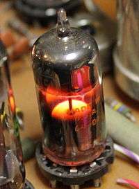
- 5331, 5332, 5514 – Directly heated power triodes, 4-pin base with anode top cap
- 5556 – Directly heated power triode, 4-pin base
- 5593 – Phasitron, a magnetically controlled beam-deflection phase modulator tube[51] similar to the 2H21, used in early FM broadcast transmitters[3][4][5]
- 5608 – Double power triode, designed for use with AC anode voltage and critical grid leak requirements
- 5651 – 86-volts, cold-cathode, glow-discharge voltage reference, 7-pin miniature base
- 5678 (CK5678 Raytheon) – 5 leads subminiature shielded pentode for RF applications
- 5691 – Special Red ruggedized long-life high-mu triode for industrial applications
- 5692 – Special Red ruggedized long-life medium-mu triode for industrial applications
- 5693 – Special Red ruggedized long-life sharp-cutoff pentode for industrial applications
- 5654, 6AK5, EF95, CV4010, 62H1P, 408A – VHF pentode; common in vintage radar IF amplifiers.
- 5704 – Subminiature diode, all-glass pigtailed
- 5727 – 650 V, 100 mAavg, 500 mApeak, 10 Asurge Indirectly heated tetrode thyratron, positive starter voltage, miniature 7-pin base
- 5729 – Beam-deflection, 30-channel analog multiplexer for telecomms transmitting channel banks, internal electrostatic focusing and deflection to determine through which one out of 30 grids the electron beam passes to the common anode.[52] Cf. 5738, 6090, 6091, 6170, 6324
- 5731 – Narrow-tolerance selected 955 Acorn triode for use in Radiosonde weather balloon transmitters
- 5734 – Mechano-electronic displacement sensor; a vacuum triode with its anode mounted on a shaft that extends through a thin, flexible metal diaphragm; shaft movement is reflected in anode current; Fres = 12 kHz[53][54]
- 5738 – Beam-deflection, secondary emission, 25-channel analog multiplexer, internal electrostatic focusing and deflection to determine which one out of 25 individually controllable dynodes receives the electron beam controlled by a common grid.[55] Cf. 5729, 6090, 6091, 6170, 6324
- 5749, 6BA6, EF93, W727 – RF pentode
- 5750, 6BE6, EK90, X727 – Heptode mixer
- 5751 – Low-voltage, low-noise avionics dual triode with separate cathodes
- 5814A – Industrial, computer-rated version of 12AU7/ECC82
- 5836, 6BL6– Sutton tube, a reflex klystron used as a 250 mW CW microwave source, 1.6 to 6.5 GHz depending upon an external cavity. 4-pin peewee base with cavity contact rings and top cap
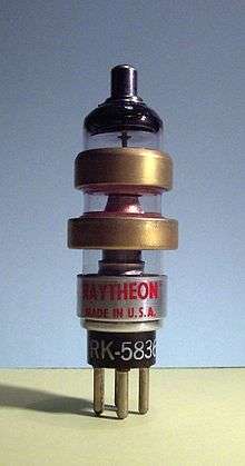 Raytheon RK5836
 - 5837, 6BM6 – Sutton tube used as a 150 mW CW microwave source, 550 MHz to 3.8 GHz depending upon an external cavity. 4-pin peewee base with cavity contact rings and top cap
- 5845 – Dual directly heated saturated-emission diode. Acts as a heating current-controlled, variable series resistor in voltage/current stabilizer circuits.
- 5876A – Glass pencil-type disk-seal UHF power triode up to 2 GHz
- 5930 – Ruggedized, directly heated power triode, 4-pin base
- 5962 – 700 V/2...55 µA Corona voltage reference, miniature 7-pin base with anode top cap
- 5963, 5964, 5965 – Dual triode, designed for high speed digital computers, has a high zero-bias anode current, identical to 12AV7
- 5998, 6336A, 6394, 6520, 6528, 7802 – Double power triodes, designed for series voltage regulator applications
6000s
- 6047 – Additron, a triple-control grid, split-anode tetrode for use as a single-bit digital full adder[56] (technically a hexode)
- 6057, 12AX7, ECC83, M8137, B339 – High-mu double triode
- 6059, 6BR7 – Low-microphonics pentode
- 6060, 12AT7, ECC81, M8162, B309 – High-mu double triode
- 6064, 6AM6, EF91, M8083, Z77 – R.F. pentode
- 6067, 12AU7, ECC82, M8136, B329 – Medium-mu double triode
- 6080, 6AS7 – Very-low impedance double power triode, designed for series voltage regulator applications, now popular for output transformerless audio amplifiers
- 6082 – Ruggedized, indirectly heated power triode, octal base
- 6090 – Beam-deflection, 18-channel analog demultiplexer for telecomms receiving channel banks, internal electrostatic focusing and deflection to determine which one out of 18 anodes receives the electron beam controlled by a common grid.[57] Cf. 5729, 5738, 6091, 6170, 6324
- 6091 – Beam-deflection, 25-channel analog multiplexer for telecomms transmitting channel banks, internal electrostatic focusing and deflection to determine through which one out of 25 grids the electron beam passes to the common anode.[58] Cf. 5729, 5738, 6090, 6170, 6324
- 6146 – 60 MHz, 120 W Power AF/RF/VHF beam pentode
- 6146B (8298A) – Improved version of 6146, 6146A and 8298.
- 6170 and 6324 – Beam-deflection, 25-channel analog multiplexer for telecomms transmitting channel banks, external focusing and deflection by a multiphase, rotating magnetic field to determine through which one out of 25 grids the electron beam passes to the common anode.[59] Cf. 5729, 5738, 6090, 6091
- 6173 – Pencil-type disk-seal UHF diode up to 3.3 GHz
- 6196 – Directly-heated dual, compensating electrometer tetrode with space charge grids for use in the 2 branches of a differential-in, differential-out bridge circuit[60]
- 6218/E80T (CV5724) – Modulated, single-anode beam deflection tube for pulse generation up to 375 MHz; shock resistant up to 500 g[61][62]
- 6351 – Secondary emission pentode for wide band RF amplifiers
- 6353 – 19.3 kV/25...1000 µA Corona voltage reference, miniature 7-pin base with anode top cap
- 6263 – Pencil-type disk-seal UHF power triode up to 500 MHz, Panode = 8 W
- 6361 – Convectron, an inclinometer tube that senses tilt from the vertical by means of different gas convections around a heating wire in a glass envelope, of two 6361s aligned in a 90° V-shaped position to each other and the heating wires connected in a bridge circuit
- 6391 – Subminiature low-microphonics pentode, 8-pin all-glass pigtailed
- 6441 – 650 V, 100 mAavg, 300 mAsurge Tacitron, a grid turn-off hydrogen thyratron with a grid that forms a shield around both the cathode and anode and separates the two by a wire mesh, so the arc discharge can be extinguished by a negative grid that surrounds the positive anode with a field of opposing polarity and inhibits conduction, taking over part of the anode current during deionisation – similar to today's GTOs; Octal base[63]
- 6462 – Magnetic pickup tube, a 1-axis beam-deflection magnetometer with approx. 1 G (100 μT) resolution; an electron beam is electrostatically centered between two anodes while no magnetic field is present; the magnetic field to be detected will then deflect the beam more towards one of the anodes, resulting in an imbalance between the two anode currents[64]
- 6550 – 20 W AF beam tetrode for high fidelity amplifiers
- 6571 – Williams-type computer memory tube[65]
- 6577 – Typotron, a charactron for text mode video rendering in early computer monitors[66]
- 6700 – 200 ns Decade counter Magnetron Beam Switching Tube, 6.3 V, 300 mA heater[67]
- 6701 – Low-voltage 500 ns decade counter Magnetron Beam Switching Tube, 6.3 V, 300 mA heater[68]
- 6703 – 500 ns Decade counter Magnetron Beam Switching Tube, 6.3 V, 300 mA heater
- 6704 – 100 ns Decade counter Magnetron Beam Switching Tube with internal spade load resistors, 6.3 V, 300 mA heater
- 6710, 6711, 6712 (High current), 6714 (Low voltage) – 2 MHz Decade counter Beam-X Switch, 6.3 V heater
- 6762 – Wamoscope, a TWT/CRT combination used to directly visualize an incoming microwave signal by electron velocity-sorting[69]
- 6835, 7570, 7571 – Single-electron gun recording storage tube, an analog video frame freezer tube. This was achieved by a CRT that writes the video image onto a thin, dielectric target and subsequently can read the generated charge pattern up to 30000 times from that target, producing a video signal containing a static shot that resembles a still photograph[70][71][72]
- 6846 – Gas-filled, three-cathode 1-bit binary counter or switching tube, 7-pin base[73]
- 6877, 7233 – Power triodes, designed for series voltage regulator applications
- 6900 – Dual power triode for pulse applications in missiles, avionics and industrial systems; noval base
- 6922 (E88CC, industrial version of 6DJ8/ECC88)
- 6973 – Power pentode similar in shape, size, and pinbase to the EL84/6BQ5, but with a high gain for more than double the output range. Popular in some makes of 1960s era guitar amplifiers, though rarely implemented in modern times.
7000s
- 7077 – Miniature all-ceramic disk-seal UHF triode
- 7105 – 12.6-volts version of 6080
- 7189/6BQ5/EL84 – AF Power pentode
- 7189A – Improved 7189
- 7199 – Split triode-pentode, noval pinbase. Similar to 6U8.
- 7229,[74] 7230,[75] 7231,[76] 7232,[77] 7439, 7440, 7441, 7595, 7596, 7597, 7598, 7599, 7600, 7602 – Krytrons, cold-cathode gas-filled trigger tubes with a primer electrode for use as a very high-speed, high-surge current switch[78] – second source to EG&G
- 7236 – Double power triode for use as long-life power amplifier in computer applications
- 7241, 7242 – Triple-grid/cathode power triodes, designed for hi-rel series voltage regulator applications
- 7266 – Miniature all-ceramic disk-seal UHF diode
- 7289 – 3 GHz, 40 W UHF planar power triode
- 7308/E188CC – Premium version of 6922
- 7360 – Beam deflection tube, used as balanced modulator/mixer up to 100 MHz[79][80][81]
- 7414 – Time Totalizer, a metal-vapor coulometer, a cold-cathode gas-discharge tube where metal is constantly sputtered off the cathode and deposited on a collector element whose resistance therefore decreases with elapsed time[82]
- 7430 – Flat-envelope version of the 6AK5/EF95 sharp-cutoff pentode for use on PCBs in Radiosonde weather balloon transmitters
- 7548 – Secondary emission hexode for pulse generator and pulse amplifier applications
- 7551 - Noval-base beam power pentode with 12-15 volt filament. 6.3 volt filament version was 7558. Used in telephony, RF amplification, and more rarely AF amplification.
- 7554 – Ceramic/metal pencil-type disk-seal SHF power triode up to 5 GHz
- 7572, 7575, 7702 – Dual-electron gun recording storage tube, a realtime analog video frame freezer tube with simultaneous R/W, and storing capability. This was achieved by a CRT/camera tube combination; the CRT part writes the video signal onto a thin, dielectric target, which can hold the generated charge pattern for many hours; the camera part reads the charge pattern from the back side of this target, producing a video signal containing a static shot that resembles a still photograph[83][84][85]
- 7586 – First Nuvistor available on the market, medium-mu triode
- 7587 – Nuvistor Sharp cutoff tetrode
- 7591 – Beam power pentode, octal pinbase. Found in many guitar amps made by Gibson and Ampeg.
- 7688, 7690 (Medium-mu), 7689 (high-mu) – triple triodes
- 7699 – Dual tetrode for wide band push-pull amplifiers
- 7762 – Shock-proof avionics AF beam power pentode
- 7763 – Beam deflection tube, used as IF amplifier/limiter where a constant phase shift over a wide range of input signal amplitudes is required[86]
- 7768 – Miniature all-ceramic disk-seal SHF triode up to 4 GHz
- 7868 – Beam power pentode, magnoval pinbase version of 7591. Found in many of the once popular Challenger series PA amps made by Bogen Communications, also found in some guitar amplifiers made by Ampeg.
- 7895 – Improved 7586 Nuvistor with higher mu
8000s
- 8011 – Micropup-type UHF power triode up to 600 MHz
- 8056 – Nuvistor triode for low supply voltage
- 8058 – Nuvistor triode with grid on envelope and an anode cap, for grounded-grid UHF circuits
- 8069 – 8 kV/23...1000 µA Corona voltage reference, cathode cylinder and anode top cap
- 8089 – 1.6 kV/20...800 µA Corona voltage reference, 2-pin all-glass pigtailed
- 8090 – 3.5 kV/50...1000 µA Corona voltage reference, 9-pin with anode top cap
- 8091 – 4 kV/50...1000 µA Corona voltage reference, 9-pin with anode top cap
- 8122 – Forced-air cooled, 300 W@470 MHz beam power tetrode
- 8256 – 3.5 kV/35...1900 µA Corona voltage reference, 2-pin all-glass pigtailed
- 8257 – 1.2 kV/15...750 µA Corona voltage reference, 2-pin all-glass pigtailed
- 8393 – Nuvistor Medium-mu triode, used in Tektronix oscilloscopes, 12.6 Volt heater
- 8469 – 400 V/5...400 µA Corona voltage reference, 2-pin all-glass pigtailed
- 8506 – Miniature all-ceramic disk-seal UHF triode
- 8514 – 1 kV/10...800 µA Corona voltage reference, 7-pin with anode top cap
- 8515 – 1.6 kV/20...950 µA Corona voltage reference, 7-pin with anode top cap
- 8526 – Nuvistor-type medium-mu dual triode
- 8873 – 500 MHz, 200 W anode dissipation power triode
- 8874 – 500 MHz, 400 W anode dissipation power triode
- 8875 – 500 MHz, 300 W anode dissipation power triode
- 8877 = 3CX1500A7 – Ceramic, forced air cooled, 1.5 kW power triode
- 8974 (X-2159) – Giant water-cooled megawatt-class tetrode used for very high-power broadcast and industrial service; possibly the most powerful tube ever commercially produced
List of European Mullard–Philips tubes, with American equivalents
Most post-war European thermionic valve (vacuum tube) manufacturers have used the Mullard–Philips tube designation naming scheme.
Special quality variants may have the letters "SQ" appended, or the device description letters may be swapped with the numerals (e.g. an E82CC is a special quality version of an ECC82)
Note: Typecode explained above. The part behind a slash ("/") is the RMA/RETMA/EIA equivalent.
A - 4 V heater
AB
- AB1 – Dual diode
- AB2 – Dual diode
ABC
- ABC1 – Dual diode - sharp-cutoff pentode, CBC1 with a different heater, 1930s European radios.
ABL
- ABL1 – Dual diode - power pentode, 1930s European radios.
AC
- AC2 – Triode for use as AF amplifier or as oscillator together with an AH1 mixer; 8-pin base, EC2 with a different heater
- AC50/4686 – 3 mAavg, 300 mApeak, Argon-filled triode thyratron, 8-pin base with grid on top cap, for relaxation oscillators up to 50 kHz
- AC100 – Triode for use as AF amplifier or as oscillator together with an AH100 mixer; AC2 with a different base
- AC101 – Triode for use as AF amplifier or as oscillator together with an AH100 mixer; AC2 with a different base
- AC701 – Subminiature AF triode, 4-pin all-glass pigtailed with grid on top cap, for condenser microphone preamplifiers
- AC761 – Subminiature AF triode, 4-pin all-glass pigtailed with grid on top wire, for microphone preamplifiers
ACH
- ACH1 – Triode-Hexode mixer
A D
- AD1 – 4.2 W Power triode
- AD100 – 1.7 W Power triode, 5-pin base
- AD101 – 1.7 W Power triode, 7-pin base
- AD102 – 5.5 W Power triode
AF
- AF2 – Remote-cutoff pentode
- AF3 – Remote-cutoff pentode. Identical to CF3 except for heater ratings
- AF7 – Sharp-cutoff pentode
- AF100 – Wide band, sharp-cutoff pentode
AH
- AH1 – Remote-cutoff Hexode for RF gain control or modulator, CH1 with a different heater
- AH100 – Remote-cutoff Hexode for RF gain control or modulator
AK
- AK1 – Octode pentagrid converter, 1930s European radios. UX7 base.
- AK2 – Octode pentagrid converter, CK1 with a different heater, 1930s European radios. Ct8 base, similar to EK2.
AL
- AL1 – AF Power pentode, 1930s European radios
- AL2 – AF Power pentode, 1930s European radios. Ct8 base.
- AL3 – AF Power pentode, 1930s European radios
- AL4 – AF Power pentode, 1930s European radios
- AL5 – Identical to EL5 except for heater ratings
- AL860 – RF/AF Power pentode, noval base
AM
- AM1 – Top-view, "Magic Cross"-type tuning indicator, EM1 with a different heater
- AM2/4677 – Top-view, "Magic Eye"-type tuning indicator, identical to CM2 and EM2 except for heater ratings
AN
- AN1 – 300 mAavg, 2 Apeak, 15 Asurge, Gas-filled triode thyratron with negative control characteristic. British 5-pin base, for industrial control applications
AX
- AX1/4652 – 500 VPIV, 125 mA Gas-filled, full-wave rectifier, 4-pin base
- Note: This particular 4652 is a Philips-proprietary designation and not an EIA number
- AX50 – 500 VPIV, 275 mA Gas-filled, full-wave rectifier, 4-pin base
AZ
- AZ1 – 100 mA Full-wave power rectifier, Ct8 base, 8-pin side-contact
- AZ2 – 160 mA Full-wave power rectifier, Ct8 base, 8-pin side-contact
- AZ3 – 120 mA Full-wave power rectifier, Ct8 base, 8-pin side-contact
- AZ4 – 200 mA Full-wave power rectifier, Ct8 base, 8-pin side-contact
- AZ11 – Full-wave power rectifier, AZ1 with G8A 8-pin German metal octal base
- AZ12 – Full-wave power rectifier, AZ4 with G8A 8-pin German metal octal base
- AZ21 – 120 mA Full-wave power rectifier, Loctal base
- AZ31 – Full-wave power rectifier, AZ1 with 5-pin Octal base
- AZ32 – Full-wave power rectifier, AZ2 with 5-pin Octal base
- AZ33 – 120 mA Full-wave power rectifier, 4-pin Octal base
- AZ41 – 70 mA Full-wave power rectifier, Rimlok base
- AZ50 – 300 mA Full-wave power rectifier, Rimlok base
B - 180 mA heater
BB
BCH
BL
- BL2 – Power pentode, CL2 with a 30 V heater and a European 5-pin base with the control grid on top cap[87][88]
C - 200 mA heater
Note: Many "C" tubes had 13V/200mA heaters, so apart from 1930s European AC/DC radios, these were also used in 12-Volts car radios[11]:6
CB
- CB1 – Dual diode, P base, 8-pin side-contact, 13 V heater, 1930s European radios.
- CB2 – Dual diode, P base, 8-pin side-contact, 13 V heater, 1930s European radios.
CBC
- CBC1 – Dual diode and triode, ABC1 with a 13 V heater, 1930s European radios.
CBL
- CBL1 – Dual diode and power pentode, 44 V heater, 1930s European radios.
- CBL6 – Dual diode and power pentode, 1930s European radios.
- CBL31 – Dual diode and power pentode, CBL1 with a different base, 1930s European radios.
CC
- CC2 – Triode, AC2 with a 13 V heater, 1930s European radios.
CCH
- CCH1 – Triode-hexode mixer, 1930s European radios.
- CCH2 – Triode-hexode mixer, 1930s European radios.
- CCH35 – Triode-hexode mixer, ECH3 with a different heater and base, 1930s European radios.
CF
- CF1 – Sharp-cutoff pentode, 13 V heater, 1930s European radios.
- CF2 – Remote-cutoff pentode, 13 V heater, 1930s European radios.
- CF3 – Remote-cutoff pentode, AF3 with a 13 V heater, 1930s European radios.
- CF7 – Sharp-cutoff pentode, AF7 with a 13 V heater, 1930s European radios.
- CF50 – Microphone preamplifier sharp-cutoff pentode
- CF51 – Microphone preamplifier sharp-cutoff pentode
CH
- CH1 – Hexode mixer, AH1 with a 13 V heater, 1930s European radios.
CK
- CK1 – Octode pentagrid converter, AK2 with a 13 V heater, 1930s European radios.
- CK3 – Octode pentagrid converter, EK3 with a different heater, 1930s European radios.
CL
- CL1 – Power pentode, 1930s European radios.
- CL2 – Power pentode, BL2 with a 24 V heater, 1930s European radios.
- CL4 – AF power pentode, 33 V heater, 1930s European radios.
- CL6 – Power pentode, 1930s European radios.
- CL33 – AF power pentode, CL4 with an octal base, 1930s European radios.
CM
- CM2 – Top-view, "Magic Eye"-type tuning indicator; has a 6.3 V/200 mA heater and was therefore marketed as C/EM2; identical to AM2 except for heater ratings
CY
- CY1 – 250 V, 80 mA Half wave rectifier, Ct8 base, 1930s European radios.
- CY2 – Separate-cathode dual[89] 250 V, 60 mA rectifier, Ct8 base, for use as half wave rectifier or as voltage doubler. 1930s European radios.
- CY31 – CY1 with International Octal base, 1930s European radios.
- CY32 – CY2 with International Octal base, 1930s European radios.
D - 1.4 V filament/heater
Note: D-type tubes except some rectifiers are directly heated.
DA
- DA50 – Subminiature diode, 3-pin all-glass pigtailed
- DA90 – Indirectly heated AM detector diode, miniature 7-pin base
- DA101 – Diode, miniature 7-pin base
DAC
- DAC21 – AM detector diode and AF triode
- DAC22 – AM detector diode and AF triode
- DAC25 – AM detector diode and AF triode
- DAC31 – AM detector diode and AF triode
- DAC32 – AM detector diode and AF triode
- DAC41w – AM detector diode and AF triode[12]
DAF
- DAF11 – AM detector diode and AF pentode, wide-range heater
- DAF26 – AM detector diode and AF pentode
- DAF40 – AM detector diode and AF pentode
- DAF41 – AM detector diode and AF pentode
- DAF70 – Subminiature AM detector diode and AF pentode, all-glass pigtailed
- DAF91/1S5 – AM detector diode and AF pentode, miniature 7-pin base
- DAF92 – AM detector diode and AF pentode, miniature 7-pin base
- DAF96/1AH5 – AM detector diode and AF pentode, miniature 7-pin base
- DAF191 – AM detector diode and AF pentode, miniature 7-pin base
- DAF961 – AM detector diode and AF pentode, miniature 7-pin base
DAH
- DAH50 – Low voltage diode-heptode with a space charge grid
DBC
- DBC21 – Dual diode and Triode
DC
- DC11 – AF driver triode for DDD11, wide-range heater
- DC25 – AF driver triode for DDD25
- DC41w – Driver triode[12]
- DC70/6375 – Subminiature UHF triode for walkie-talkies, all-glass pigtailed
- DC80/1E3 – Triode, oscillator/mixer/amplifier
- DC90 – Triode, FM receiver oscillator/mixer/amplifier, miniature 7-pin base
- DC96 – Triode, FM receiver oscillator/mixer/amplifier, miniature 7-pin base[88]
- DC760 – Subminiature electrometer inverted triode for probes, all-glass pigtailed
- DC761 – Subminiature UHF triode, all-glass pigtailed
- DC762 – Subminiature electrometer inverted triode for probes, 100 fA grid current, all-glass pigtailed
- D1C (957) – Acorn UHF triode
- D2C (958) – Acorn UHF triode
DCC
- DCC90 – Dual triode, RF amplifier or oscillator, miniature 7-pin base
DCF
- DCF60/1V6 – Triode and pentode, oscillator/mixer, all-glass 7-pin pigtailed
DCH
DD
- DD960 – VHF power triode, miniature 7-pin base
DDD
DF
- DF11 – Remote-cutoff RF/IF pentode, wide-range heater
- DF21 – Sharp-cutoff RF/IF/AF pentode
- DF22 – Remote-cutoff RF/IF pentode
- DF25 – Remote-cutoff RF/IF pentode
- DF26 – Sharp-cutoff RF/IF pentode
- DF33 – Remote-cutoff RF/IF pentode
- DF41w – Remote-cutoff RF/IF pentode[12]
- DF60/5678 – Subminiature sharp-cutoff RF/IF/AF pentode, all-glass pigtailed
- DF61 – Subminiature sharp-cutoff RF or mixer pentode, all-glass pigtailed
- DF62/1AD4 – Subminiature sharp-cutoff RF pentode, all-glass pigtailed, for use as RF/IF stage
- DF63 – Subminiature remote-cutoff RF pentode, all-glass pigtailed, for use as RF/IF stage
- DF64 – Subminiature AF pentode, all-glass pigtailed, for use in hearing aids
- DF65 – Subminiature AF pentode, all-glass pigtailed, for use in hearing aids
- DF66 – Subminiature AF pentode, all-glass pigtailed, for use in hearing aids
- DF67/6008 – Subminiature AF pentode, all-glass pigtailed, for use in hearing aids
- DF70 – Subminiature AF pentode, all-glass pigtailed, for use in hearing aids
- DF72 – Subminiature sharp-cutoff RF pentode, all-glass pigtailed, for use as RF/IF stage
- DF73 – Subminiature remote-cutoff RF pentode, all-glass pigtailed, for use as RF/IF stage
- DF91/1T4 – Remote-cutoff RF/IF pentode, miniature 7-pin base
- DF92/1L4 – Sharp-cutoff RF/IF pentode, miniature 7-pin base
- DF96/1AJ4 – Remote-cutoff RF/mixer pentode, miniature 7-pin base
- DF97/1AN5 – Remote-cutoff RF/IF pentode, miniature 7-pin base
- DF161 – Subminiature AF pentode, all-glass pigtailed, for use in hearing aids
- DF167 – Subminiature AF pentode, all-glass pigtailed, for use in hearing aids
- DF191 – RF pentode, miniature 7-pin base
- DF651 – (CK549DX) Subminiature AF pentode, all-glass pigtailed, for use in hearing aids
- DF668 – Subminiature RF pentode, all-glass pigtailed
- DF669 – Subminiature RF/IF pentode, all-glass pigtailed
- DF703 – (CK5886) Subminiature electrometer pentode, envelope has a moisture-repellent coating, all-glass pigtailed, for probe amplifiers
- DF904/1U4/5910 – Sharp-cutoff SW/VHF pentode, miniature 7-pin base
- DF906 – Sharp-cutoff SW/VHF pentode, miniature 7-pin base
- DF961 – Sharp-cutoff SW/VHF pentode, miniature 7-pin base
- D1F – D11F with a hand grip
- D2F – D12F with a hand grip
- D3F (959) – Acorn VHF pentode
- D11F – Acorn remote-cutoff RF/IF/AF pentode for portable transceivers
- D12F – Acorn RF/IF/AF pentode for portable transceivers
DK
- DK21 – Octode beam pentagrid converter
- DK32/1A7 – Heptode pentagrid converter
- DK40 – Octode pentagrid converter
- DK91/1R5 – Heptode pentagrid converter, miniature 7-pin base
- DK92/1AC6 – Heptode pentagrid converter, miniature 7-pin base
- DK96/1AB6 – Heptode pentagrid converter, miniature 7-pin base
- DK192 – Heptode pentagrid converter, miniature 7-pin base
- DK962 – Heptode pentagrid converter, miniature 7-pin base
DL
- DL11 – 350 mW AF Power pentode, wide-range heater
- DL21 – 700 mW AF Power pentode
- DL25 – Power pentode
- DL29/3D6 – Power pentode
- DL33/3Q5GT – 400 mW AF Power pentode
- DL35 – 400 mW Power pentode
- DL41 – 600 mW Power pentode
- DL41w – Bowl Power pentode[12]
- DL64 – Subminiature AF power pentode, all-glass pigtailed, for use in hearing aids, VA = 15 V, VAmax = 45 V
- DL65 – Subminiature AF power pentode, all-glass pigtailed, for use in hearing aids, DL67/6007 with a different pinout, VA = 22.5 V, VAmax = 45 V
- DL66 – Subminiature AF power pentode, all-glass pigtailed, for use in hearing aids, VA = 22.5 V, VAmax = 45 V
- DL67/6007 – Subminiature AF power pentode, all-glass pigtailed, for use in hearing aids, DL65 with a different pinout, VA = 22.5 V, VAmax = 45 V
- DL68 – Subminiature AF power pentode, all-glass pigtailed, for use in hearing aids, VA = 22.5 V, VAmax = 45 V
- DL69 – Subminiature power pentode, all-glass pigtailed, VA = 90 V
- DL70 – Subminiature VHF power pentode up to 200 MHz, all-glass pigtailed, for use in walkie-talkies, VA = 150 V
- DL71 – Subminiature AF power pentode, all-glass pigtailed, for use in hearing aids, VA = 22.5 V, VAmax = 45 V
- DL72 – Subminiature AF power pentode, all-glass pigtailed, for use in hearing aids, VAmax = 45 V
- DL73 (CV2299) – Subminiature VHF power pentode up to 200 MHz, all-glass pigtailed, for use in walkie-talkies, VA = 150 V
- DL91/1S4 – Power pentode, miniature 7-pin base
- DL92/3S4 – 270 mW AF Power pentode, miniature 7-pin base
- DL93/3A4 – 1.2 W RF/AF Power pentode, miniature 7-pin base
- DL94/3V4 – 1.3 W AF Power pentode, miniature 7-pin base
- DL95/3Q4 – 270 mW AF Power pentode, miniature 7-pin base
- DL96/3C4 – 440 mW AF Power pentode, miniature 7-pin base
- DL98/3B4 – 1.25 W RF power pentode up to 100 MHz, miniature 7-pin base
- DL161 – Subminiature AF power pentode, all-glass pigtailed, for use in hearing aids
- DL167 – 1.8 mW Subminiature AF power pentode, all-glass pigtailed, for use in hearing aids
- DL192 – 150 mW AF Power pentode, miniature 7-pin base
- DL193 – 650 mW AF Power pentode, miniature 7-pin base
- DL620 – 110 mW Subminiature power pentode, all-glass pigtailed, VAmax = 90 V
- DL907 – SW/VHF power pentode, miniature 7-pin base
- DL962 – 150 mW AF power pentode, miniature 7-pin base
- DL963 – RF/AF power pentode, miniature 7-pin base
DLL
- DLL21 – 1.5 W AF Dual power pentode
- DLL101 – Dual power pentode, miniature 7-pin base
- DLL102 – Dual power pentode, miniature 7-pin base
DM
- DM21 – Top-view, "Magic Eye"-type tuning indicator
- DM70/1M3 – Side-view, subminiature band-and-dot-type tuning/level indicator, all-glass pigtailed
- DM71/1N3 – Side-view, subminiature band-and-dot-type tuning/level indicator, all-glass pigtailed
- DM160/6977 (ИВ-15) – First vacuum fluorescent display, single segment, side-view, for use as flip-flop status indicator in transistorized computers. All-glass pigtailed
DY
- DY30 – 30 kV CRT EHT rectifier
- DY51 – Half-indirectly-heated 15 kV portable-TV CRT EHT rectifier, filament internally connected to cathode, all-glass, filament pigtails on one end, anode pigtail on the other
- DY70 – 10 kV CRT EHT rectifier, 3-pin all-glass pigtailed, anode on top wire
- DY80 – 23 kV CRT EHT rectifier, noval base
- DY86/1S2 – Half-indirectly-heated 18 kV CRT EHT rectifier, noval base, filament internally connected to cathode. Identical to EY86 except for heater ratings
- DY87/1S2A – DY86/1S2 with chemically treated envelope to avoid flush-over in high-humidity and low atmospheric-pressure conditions. Identical to EY87 except for heater ratings
- DY802 – Half-indirectly-heated 23 kV CRT EHT rectifier, noval base, filament internally connected to cathode. Identical to PY802 except for heater ratings
- DY900 – Half-indirectly-heated 16 kV CRT EHT rectifier, miniature 7-pin base, filament internally connected to cathode
E - 6.3 V heater
EA
- EA40 – 7 kV, 25 mA Diode, 4-pin Rimlock base
- EA50/2B35 – Diode for TV detectors, 3+1-pin all-glass pigtailed with anode on top wire
- EA52/6923 – Instrumentation rectifier diode up to 1 GHz, 3-pin all-glass pigtailed with anode top cap
- EA53 – Co-axial instrumentation rectifier diode up to 1 GHz, all-glass with anode top cap
- EA76 – Diode, 5-pin all-glass pigtailed
- EA111 – Diode for time bases, 8-pin base
- EA766 – Diode, 5-pin all-glass pigtailed
- EA960 – 100 VPIV VHF Diode, miniature 7-pin base
- EA961 – 2 kVPIV VHF Diode, miniature 7-pin base
- EA962 – 100 VPIV VHF Diode with extremely small distance between cathode and anode for extended frequency range, miniature 7-pin base
EAA
- EAA11 – Dual diode, 8-pin base
- EAA91/6AL5 – Dual diode with separate cathodes, miniature 7-pin base, identical to HAA91/12AL5, UAA91 and XAA91/3AL5 except for heater ratings, EB91 with a shorter envelope
- EAA171 – Dual diode, separate cathodes, gnome tube
- EAA901S/5726 – Dual RF diode, miniature 7-pin base
- E91AA – Dual diode, miniature 7-pin base
EAB
- EAB1 – Triple diode with common cathode
EABC
- EABC80/6AK8 – High-mu triode, triple low-voltage diode (two on common cathode with triode, one with independent cathode). Miniature 9-pin noval base, used as an AF amplifier, AM detector and ratio detector in AC-powered post-war European AM/FM radios. Electronically identical to American types 6AK8 (usually marked 6AK8/EABC80), 6T8, and 6T8A; also DH719. Identical to 5T8, 6T8, HABC80/19T8, PABC80/9AK8 and UABC80/27AK8 except for heater ratings
EAC
- EAC91 – Diode/triode UHF mixer
EAF
- EAF21 – Diode - pentode, UAF21 with a different heater
- EAF41 – Diode - remote-cutoff RF/IF/AF pentode, Rimlock base, UAF41 with a different heater
- EAF42/6CT7 – Diode - remote-cutoff RF/IF/AF pentode, Rimlock base
- EAF801 – Diode - remote-cutoff pentode, Noval base
EAM
- EAM86/6GX8 – Diode - top-view, band-type tuning/level indicator
EB
- EB1 – Low-power dual diode
- EB2 – Low-power dual diode[87]
- EB4 – Low-power dual diode, identical to EB11 or EB34 except for basing
- EB11 – Low-power dual diode, identical to EB4 or EB34 except for basing
- EB34 – Low-power dual diode, identical to EB4 or EB11 except for basing
- EB40 – Low-power dual diode
- EB41 – Low-power dual diode
- EB91 – Dual diode with separate cathodes, miniature 7-pin base, for FM ratio detectors, EAA91/6AL5 with a longer envelope
EBC
- EBC1 – Low-power dual diode and triode, ABC1 with a different heater
- EBC3 – Low-power dual diode and triode
- EBC11 – Low-power dual diode and triode
- EBC33 – Low-power dual diode and triode, EBC3 with a different base
- EBC41 – Low-power dual diode and triode, EBC81/6BD7A with a different basing
- EBC81/6BD7A – Low-power dual diode and triode, EBC41 with a different basing
- EBC90/6AT6 – High-mu triode and common cathode dual diode, miniature 7-pin base, HBC90/12AT6 with a different heater
- EBC91/6AV6 – High-mu AF triode and common cathode dual diode, for use in FM ratio detectors, miniature 7-pin base, HBC91/12AV6 with a different heater
EBF
- EBF2 – Common-cathode dual diode and remote-cutoff RF/IF/AF pentode, P base, identical to EBF11 and EBF35 except for basing
- EBF11 – Common-cathode dual diode and RF/IF/AF pentode, Y base, identical to EBF2 and EBF35 except for basing, and to VBF11 except for heater ratings
- EBF15 – Dual diode and pentode, UBF15 with a different heater
- EBF32 – Common-cathode dual diode and remote-cutoff RF/IF pentode, 8-pin base with g1 on cap
- EBF35 – Common-cathode dual diode and remote-cutoff RF/IF pentode, 8-pin base with g1 on cap, identical to EBF2 and EBF11 except for basing
- EBF80/6N8 (WD709) – Common-cathode dual diode and remote-cutoff pentode, noval base
- EBF83/6DR8 – Common-cathode dual diode and pentode, anode voltage 6 to 50 V, for use as IF amplifier, detector and AGC diode in vehicle equipment, noval base
- EBF89/6DC8/7125 – Common-cathode dual diode and RF/IF pentode, noval base
- EBF171 – Dual Diode and remote-cutoff RF/IF/AF pentode; the first gnome tube, a modified and repackaged EBF11
EBL
- EBL1 – Dual diode and power pentode, identical to EBL21 and EBL31 except for basing and heater ratings
- EBL21 (WD709) – Dual diode and power pentode, identical to EBL1 and EBL31 except for basing and heater ratings
- EBL31 – Dual diode and power pentode, identical to EBL1 and EBL21 except for basing and heater ratings
- EBL71 – Dual diode and power pentode
EC
- EC2 – Triode for use as AF amplifier or as oscillator, 8-pin base, AC2 with a different heater
- EC40 – VHF Triode up to 500 MHz, EC80 with a different basing
- EC41 – UHF oscillator triode, EC81 with a different basing
- EC50 – Helium-filled triode thyratron for use as a horizontal sweep, sawtooth waveform generator in oscilloscopes
- EC52 – RF triode for use as an oscillator
- EC53 – VHF triode for use as an oscillator up to 600 MHz
- EC55/5861 (R243) – 3 GHz, 10 W Disk-seal UHF triode
- EC56 – 4 GHz Disk-seal microwave triode
- EC57 (EC157) – Disk-seal microwave triode
- EC70/6778 – Subminiature UHF triode for use as an oscillator in the 500 MHz range, 8-pin all-glass pigtailed
- EC71/5718 – Subminiature UHF triode up tp 1 GHz, for use as an oscillator in the 500 MHz range, 8-pin all-glass pigtailed
- EC80/6Q4 – VHF Triode up to 500 MHz
- EC81/6R4 – UHF oscillator triode
- EC84/6AJ4 – High-mu triode
- EC86/6CM4 – UHF triode, PC86/4CM4 with a different heater
- EC88/6DL4 – UHF triode, PC88/4DL4 with a different heater. This and the EC86 were often encountered in UHF TV tuners, the latter as a self oscillating mixer
- EC90/6C4 – 3.6 W Small-power VHF triode up to 150 MHz; single ECC82/12AU7 system
- EC91/6AQ4 – VHF triode up to 250 MHz
- EC92/6AB4 – VHF triode for FM receiver frontends, single ECC81/12AT7 system, UC92/9AB4 with a different heater
- EC94/6AF4 – UHF mixer/oscillator triode
- EC95 – VHF triode with variable mutual conductance, PC95 with a different heater
- EC97/6FY5 – Frame-grid VHF triode, identical to PC97/4FY5 and XC97 except for heater ratings
- EC98 – UHF triode
- EC157/8108 – 4 GHz, 12.5 W Disk-seal microwave triode
- EC158 – Low-voltage, 4 GHz, 30 W disk-seal microwave triode
- EC760 (5718) – Subminiature VHF mixer/oscillator triode up to 500 MHz, 7-pin all-glass pigtailed
- EC860 – 20 mAavg, 500 mApk Helium-filled grid-turn-off triode thyratron e.g. for relaxation oscillators up to 150 kHz, noval base
- EC900 – VHF triode, PC900 with a different heater
- EC1000 – Triode for use as amplifier in probes
- EC1030 – Indirectly heated UHF triode, hot-standby (no cathode current) resistant, all-glass pigtailed with 8 tinned, 38 mm long wires
- EC1031 – EC1030 with 5.5 mm long, gold-plated pins for insertion into a special socket
- EC8010 – UHF triode for use as amplifier or oscillator up to 1 GHz
- EC8020 – UHF triode
- E1C/4671 (955) – Acorn UHF triode
- E20C – RF triode for wide band cascode circuits, Loctal B8G base[88]
- E86C (EC806S) – UHF triode up to 800 MHz, gold-plated pins
- E88C/8255 – UHF triode for grounded-grid amplifiers, up to 1 GHz
ECC
- ECC32/6SN7 – Separate cathodes dual AF triode, octal base
- ECC33 – Separate cathodes, high-mu dual triode for use as a flip-flop, octal base
- ECC34 – Separate cathodes, dual triode for use as a CRT vertical-deflection power multivibrator, octal base
- ECC35/6SL7 – Separate cathodes, high-mu AF dual triode, octal base
- ECC40 – Separate cathodes, AF dual triode, 8-pin Rimlock base
- ECC70/6021 – Separate cathodes, subminiature VHF medium-mu dual triode, 8-pin all-glass pigtailed
- ECC81/12AT7(6060, M8162, B309) – High-mu dual triode, for use as RF amplifier/mixer in VHF circuits, noval base
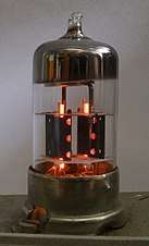 ECC83/12AX7
 - ECC82/12AU7 (6067, M8136, B329) – Medium-mu dual triode for use as AF amplifier in TV receivers, noval base, identical to XCC82 except for heater ratings. Two EC90/6C4s in one envelope;[38] however, due to the lack of screening between the two sections, it loses EC90's 150 MHz VHF capability
- ECC83/12AX7 (6057, M8137, B339) – High-mu dual triode for use as a high-gain AF amplifier, noval base
- ECC84/6CW7 – Dual VHF triode for grounded-grid/cascode amplifiers in TV tuners; section 1 cathode is connected to two adjacent pins and the screen between the two sections is internally connected to the section 2 grid; noval base. Identical to PCC84/7AN7 and UCC84 except for heater ratings
- ECC85/6AQ8 – Dual triode for use as VHF oscillator/mixer up to 200 MHz, noval base, identical to HCC85/17EW8, PCC85/9AQ8 and UCC85 except for heater ratings
- ECC86/6GM8 – Dual low (6.3-25 V) anode voltage triode, noval base, for use in VHF tuners in vehicle equipment
- ECC87/6085 – Renamed to E80CC/6085
- ECC88/6DJ8 – Dual triode used as cascode RF amplifier in TV tuners and VHF receiver front ends, or as general-purpose instrumentation dual triode, noval base, PCC88/7DJ8 with a different heater
- ECC89/6ES8 – Dual Triode used as cascode RF amplifier in TV tuners and VHF receiver front ends, or as general-purpose instrumentation dual triode, noval base
- Notes:
- All ECC8x have separate cathodes
- ECC81, 82 & 83 have the individual triode heaters internally series-connected, with the midpoint on a separate pin, so they could be run on both 6.3 V and 12.6 V (hence RETMA lists them as 12V types), which was useful in dual-system (6V and 12V) car radios
- All other ECC8x have no heater midpoint tap; ECC85, 86 & 88 have the freed-up pin being used for an internal screen between the sections
- ECC84 & 85 have their heaters internally paralleled; ECC86 & 88 have their heaters internally series-connected
- Notes:
- ECC91/6J6 – Common cathode dual VHF triode, miniature 7-pin base
- ECC92 – Common cathode dual triode for use as a flip-flop in computers, miniature 7-pin base
- ECC99 – Separate cathodes dual RF triode, noval[89] base
- ECC171 – Separate cathodes and separate heaters dual triode, 11-pin gnome tube with internal shield
- ECC180/6BQ7A – Separate cathodes, dual VHF triode for cascode amplifiers
- ECC186/7316 – Separate cathodes, dual triode for use in digital computers, withstands zero cathode current for extended periods of time
- ECC189/6ES8 – Separate cathodes, dual variable-mu VHF triode for cascode amplifiers; identical to PCC189/7ES8, XCC189/4ES8 and YCC189/5ES8 except for heater ratings
- ECC230/6AS7G/6080 – Separate cathodes, dual low-mu power[89] triode for use as series regulator in DC power supplies, servo applications, or as a horizontal booster triode in TV monitors, 8-pin base
- ECC801S/6201 – Separate cathodes, dual RF triode
- ECC802S/6189 – Separate cathodes, dual AF triode
- ECC803S/6057 – Separate cathodes, dual low-microphonics AF triode
- ECC807S – Separate cathodes, dual AF triode for high-gain preamplifiers
- ECC808/6KX8 – Separate cathodes, dual AF triode for use as record head output tube in tape recorders
- ECC812 – Separate cathodes, dual shielded triode for color TV chrominance outputs in SECAM TV receivers
- ECC832/12DW7/7247 – Dual AF triode, a combination of one ECC83/12AX7 system for use as a high-gain amplifier and one ECC82/12AU7 system for use as a phase inverter or cathode follower
- ECC960 – Common cathode, dual triode for use as a flip-flop in computers
- ECC2000 – VHF separate cathodes, dual triode with neutralization screen, for use in cascode amplifiers up to 300 MHz, 10-pin base
- ECC8100 – VHF separate cathodes, dual triode with neutralization screen ("Neutrode") connected to the heater, for use in cascode amplifiers, noval base
- E80CC/6085 – Separate cathodes, dual triode for use as DC or AF amplifier
- E81CC/6201 – Separate cathodes, dual triode for AF and RF amplifiers, mixers up to 300 MHz, oscillators, impulse circuits; withstands zero cathode current for extended periods of time
- E82CC/6189 – Separate cathodes, dual triode for use as amplifier or multivibrator
- E83CC/6681 – Separate cathodes, low-microphonics dual triode
- E88CC/6922 – Separate cathodes, dual triode, gold-plated pins
- E90CC/5920 – Common cathode, dual triode for use as a flip-flop in computers
- E92CC – Common cathode, dual triode for use as a flip-flop in computers
- E180CC/7062 – Separate cathodes, dual triode for use as a flip-flop in computers
- E181CC – Separate cathodes, dual triode for use in digital computers, withstands zero cathode current for extended periods of time
- E182CC/7119 – Separate cathodes, dual triode for use as a flip-flop in computers
- E188CC/7308 – Separate cathodes, dual triode for use as RF/IF/AF amplifier
- E283CC – Separate cathodes, dual triode for use as AF or instrumentation amplifier
- E288CC/8223 – Separate cathodes, dual triode for use in IF, RF and cascode amplifiers
ECF
- ECF1 – Triode - Pentode
- ECF12 – Triode - Pentode
- ECF80/6BL8 – VHF mixer/oscillator triode/pentode, identical to LCF80/6LN8, PCF80/9A8, UCF80 and XCF80/4BL8 except for heater ratings
- ECF82/6U8 – Triode - Pentode. Identical to PCF82/9U8A and XCF82 except for heater ratings
- ECF83 – Triode - remote-cutoff pentode, low microphonics, for vehicle equipment
- ECF86/6HG8 – VHF mixer/oscillator triode/pentode, identical to LCF86/5HG8, PCF86/7HG8, 8HG8 and XCF86/4HG8 except for heater ratings
- ECF174 – Triode and pentode, gnome tube
- ECF200/6X9 – Triode and pentode for use as IF amplifier in TV receivers, decal base, PCF200 with a different heater
- ECF201/6U9 – Triode and pentode for use as IF amplifier and sync sep in TV receivers, decal base, identical to LCF201/5U9 and PCF201 except for heater ratings
- ECF202 – Triode and pentode for use as SECAM chroma signal demodulators in analog color TV receivers, decal base
- ECF801/6GJ7 – Triode and pentode for use as VHF mixer in TV receivers, noval base, identical to LCF801/5GJ7, PCF801/8GJ7 and XCF801/4GJ7 except for heater ratings
- ECF802/6JW8 – Triode and pentode for use as reactance and sinewave oscillator in TV receivers, noval base, identical to LCF802/6LX8, PCF802/9JW8 and 5JW8 except for heater ratings
- ECF804 – Triode and pentode for use as wide band amplifier, noval base, PCF804 with a different heater
- ECF805 – Triode and pentode, noval base, PCF805/7GV7 with a different heater
- ECF812/6FL2 – Triode and beam tetrode, noval base, PCF812/30FL2 with a different heater
- ECF8070 – Triode - Pentode
- E80CF/7643 – Triode - pentode
ECH
- ECH3 – Ct8-based Triode/hexode oscillator/mixer, ECH33 with a different basing
- ECH4 – Ct8-based Triode/heptode oscillator/mixer, ECH21 with a different basing
- ECH11 (X143) – Triode/hexode oscillator/mixer, VCH11 with a different heater
- ECH21 (X143) – Triode/heptode oscillator/mixer, ECH4 with a different basing
- ECH33 – Triode/hexode oscillator/mixer, ECH3 with a different basing
- ECH35 (X147) – Triode/hexode oscillator/mixer
- ECH41 – Triode/hexode oscillator/mixer
- ECH42/6CU7 – Triode/hexode oscillator/mixer, UCH42 with a different heater
- ECH43 – Triode/hexode oscillator/mixer, low-microphonics version of ECH42; UCH43 with a different heater
- ECH71 – Triode/heptode oscillator/mixer
- ECH80/6AN7 – Triode-hexode oscillator/mixer[88]
- ECH81/6AJ8 (X719) – Triode/heptode oscillator/mixer, XCH81 with a different heater
- ECH83/6DS8 – Low (6.3-25 V) anode voltage, Triode/heptode oscillator/mixer, for use in vehicle equipment
- ECH84 – Triode/heptode oscillator/mixer
- ECH171 – Triode/remote-cutoff heptode Mixer, gnome tube
- ECH200 – Triode/heptode, for TV sync sep, PCH200 with a different heater
- ECH8000 – Triode/remote-cutoff heptode oscillator/mixer
ECL
- ECL11 – Triode - power tetrode
- ECL80/6AB8 – Triode - power pentode
- ECL81 – Triode - power pentode. Identical to PCL81 except for heater ratings
- ECL82/6BM8 – AF triode - AF power pentode, identical to PCL82/16A8, UCL82/50BM8 and XCL82 except for heater ratings
- ECL83 – Triode - power pentode, PCL83 with a different heater
- ECL84/6DX8 – TV sync sep triode - CRT cathode drive power pentode, identical to LCL84/10DX8, PCL84/15DQ8 and XCL84/8DX8 except for heater ratings
- ECL85/6GV8 – Triode - power pentode used in TV receivers for vertical timebase, generally as a multivibrator, with the pentode section doubling as one half of the multivibrator and the power output device, identical to LCL85/10GV8, PCL85/18GV8 and XCL85/9GV8 except for heater ratings
- ECL86/6GW8 – AF Triode - AF power pentode, used for audio amplification in European TV receivers, PCL86/14GW8 with a different heater
- ECL113 – Triode - AF power pentode, Rimlock Pico-8 base
- ECL200 – Triode - CRT drive power pentode, decal base, PCL200 with a different heater
- ECL802 – Triode - Power pentode for use as vertical oscillator and output tube in TV receivers
- ECL805 – Triode - Power pentode with separate cathodes, PCL805 with a different heater
ECLL
- ECLL800 – Triode and dual screened power pentode, for 9.2 W (Class-B) or 8.5 W (Class-AB) AF push-pull power amplifiers. The triode shares its control grid with the 1st pentode and acts as a phase inverter for the 2nd pentode; both pentodes share screen and suppressor grids; noval base
ED
- ED111 – 6 W VHF power triode up to 85 MHz
- ED500 – Identical to PD500 except for heater ratings; considerable x-radiation despite the envelope being fabricated from lead glass
- ED501 – 27 kV Color CRT EHT shunt stabilizer triode
- ED8000 – Power triode for use in series-pass voltage regulators
EDD
- EDD11 – Dual power triode
- EDD171 – Dual high-mu power triode, gnome tube
EE
- EE58L - RF Output Triode, used at ATC transponders.
- EE1/4696 (EEP1) – Single-ended secondary emission amplifier for use as a wide band amplifier and phase inverter
- EE50 – Single-ended secondary emission amplifier for use in TV receivers
EEL
- EEL71 – AF Tetrode - AF power pentode, 8-pin base, for use as audion detector, AF preamplifier, AF power amplifier
- EEL171 – Remote-cutoff tetrode and 4-Watt power pentode, gnome tube
EEP
- EEP1 See EE1/4696
EF
- EF1 – RF/IF Pentode[87]
- EF2 – Remote-cutoff RF/IF pentode[87]
- EF3 – Remote-cutoff RF/IF pentode[87]
- EF5 – Remote-cutoff pentode
- EF6 – RF Pentode, EF36 with a different basing
- EF7 – RF/IF Pentode[87]
- EF8 – Selektode, a remote-cutoff pentode with a beam-forming extra grid between control and screen grids, intended to reduce screen current and hence anode/screen grid distribution noise (technically a hexode), EF38 with an 8-pin, side-contact base
- EF9 – Pentode, identical to EF22, EF39/6K7 and EF41/6CJ5 except for basing
- EF11 – Remote-cutoff pentode, EF111 with a different basing
- EF12 – Pentode, EF112 with a different basing
- EF13 – Remote-cutoff pentode
- EF14 – Sharp-cutoff pentode, 8-pin base, identical to UF14 and VF14 except for heater ratings
- EF15 – Remote-cutoff pentode, UF15 with a different heater
- EF22 – Pentode, identical to EF9, EF39/6K7 and EF41/6CJ5 except for basing
- EF27 – Pentode
- EF36 – Pentode, EF6 with a different basing
- EF37/6J7 – Sharp-cutoff pentode for use as a tuned RF amplifier, a (second) detector, or an AF amplifier; octal base with control grid on top-cap
- EF38 – EF8 with an Octal base[88]
- EF39/6K7 – Remote-cutoff RF pentode for use as an IF amplifier or as a superheterodyne mixer (1st detector). Also used in test equipment. Octal base with control grid on top-cap, identical to EF4, EF22 and EF41/6CJ5 except for basing
- EF40 – AF Pentode
- EF41/6CJ5 (62VP) – Remote-cutoff pentode, identical to EF4, EF22 and EF39/6K7 except for basing
- EF42 – Pentode, EF52 with a different basing
- EF43 – Remote-cutoff pentode
- EF50 (EF53) – Remote-cutoff pentode for use in the IF stages of 1940s TV and radar receivers
- EF51 – Remote-cutoff pentode
- EF52 – Pentode, EF42 with a different basing
- EF54 – Pentode
- EF55 – Pentode
- EF70 – Subminiature pentode, suppressor grid available on separate pigtail and internally connected to a separate diode to prevent positive grid voltage, for use as a NAND gate in coincidence circuits; all-glass 8-pin pigtailed
- EF71/5899 (EF731) – Subminiature remote-cutoff pentode, all-glass 8-pin pigtailed
- EF72 – Subminiature sharp-cutoff RF pentode, all-glass 8-pin pigtailed
- EF73 – Subminiature AF pentode, all-glass 8-pin pigtailed
- EF74 – Subminiature, low-microphonics pentode, all-glass 8-pin pigtailed
- EF80/6BX6 (Z152) – Sharp-cutoff RF/IF/Video pentode, noval base
- EF83 – Remote-cutoff AF pentode, Noval base
- EF85/6BY7 (W719) – Remote-cutoff wideband RF pentode, noval base, identical to HF85 and XF85 except for heater ratings
- EF86/6BK8 (6267, Z729) – AF Pentode. Identical to PF86 and UF86 except for heater ratings, Noval base
- EF89/6DA6 – Remote-cutoff RF pentode, Noval base
- EF91/6AM6 (6064, Z77, M8083, 8D3) – Sharp-cutoff pentode, Miniature 7-pin base
- EF92/6CQ6 (M8161) – Remote-cutoff RF pentode, Miniature 7-pin base
- EF93/6BA6 (W727) – Remote-cutoff RF pentode, miniature 7-pin base, HF93/12BA6 with a different heater
- EF94/6AU6 – Sharp-cutoff RF/IF/AF pentode, miniature 7-pin base, identical to HF94/12AU6 and XF94/3AU6 except for heater ratings
- EF95/6AK5 (5654, 408A, 62H1P, CV4010) – RF Pentode, Miniature 7-pin base
- EF96/6AG5 – Pentode, Miniature 7-pin base
- EF97/6ES6 – Low (6.3-25 V) anode voltage, remote-cutoff RF/IF pentode, for use in vehicle equipment, Miniature 7-pin base
- EF98/6ET6 – Low (6.3-25 V) anode voltage, sharp-cutoff pentode, for use as oscillator or IF/AF amplifier in vehicle equipment, Miniature 7-pin base
- EF111 – Remote-cutoff pentode, EF11 with a different basing
- EF112 – Pentode, EF12 with a different basing
- EF172 – RF/IF/AF Pentode, gnome tube
- EF174 – Pentode, gnome tube
- EF175 – Remote-cutoff RF/IF pentode, gnome tube
- EF176 – VHF Pentode, gnome tube
- EF177 – VHF Pentode, gnome tube
- EF183/6EH7 – Frame grid, remote-cutoff IF pentode for use in TV receivers, identical to LF183/YF183/4EH7 and XF183/3EH7 except for heater ratings[90]
- EF184/6EJ7 – Frame-grid, sharp-cutoff IF pentode for use in TV receivers, identical to LF184/YF184/4EJ7 and XF184/3EJ7 except for heater ratings[91]
- EF410 – RF/IF Pentode, Rimlock B8A base
- EF730/5636 – Subminiature dual-control, sharp-cutoff RF/IF pentode for use as a gated or gain-controlled amplifier, 8-pin all-glass pigtailed, similar to 5784
- EF731 – Subminiature remote-cutoff RF pentode, 8-pin all-glass pigtailed
- EF732 – Subminiature sharp-cutoff RF pentode, 8-pin all-glass pigtailed
- EF734 – Subminiature sharp-cutoff RF pentode, 8-pin all-glass pigtailed
- EF762 – Subminiature sharp-cutoff RF/IF pentode, 8-pin all-glass pigtailed
- EF800 – Long-life sharp-cutoff RF/IF pentode
- EF802 – Long-life RF/IF pentode
- EF804 – AF low-hum, low-microphonics pentode
- EF804S – Ruggedized, long-life version of EF804
- EF805S – Long-life remote-cutoff RF/IF pentode
- EF806S – Ruggedized, long-life AF pentode
- EF816 – Dual-anode pentode for TV receiver sync separation service
- EF860 – Long-life sharp-cutoff RF pentode for use as preamplifier in telecomms wide-area receivers. Identical to IF860 except for heater ratings (300mA)
- EF5000 – secondary emission wide band pentode, noval base
- EF8010 – Remote-cutoff RF/IF pentode
- E1F/4672 (954) – Acorn UHF pentode
- E2F/4695 (956) – Acorn UHF pentode
- E3F – E13F with a hand grip
- E13F – Acorn remote-cutoff RF/IF/AF signal/power pentode for portable transceivers
- E80F/6084 – AF pentode, gold-plated pins
- E83F/6689 – Long-life, wide band pentode for use in telephone equipment, gold-plated pins
- E90F/6BH6/7693 – RF Pentode
- E95F/6AK5W/5654 – Pentode
- E99F/6BJ6/7694 – Remote-cutoff RF pentode
- E180F/6688 – Wide band pentode, wideband amplifier for professional equipment
- E186F/7737 – Wide band pentode, wideband amplifier
- E280F/7722 – Wide band pentode, wideband amplifier
- E282F – Pentode, wideband amplifier up to 250 MHz
- E810F/7788 – Wide band pentode, gold-plated pins
EFF
- EFF51 – Dual VHF pentode up to 500 MHz
EFL
- EFL200/6Y9 – Sync sep pentode and CRT cathode drive power pentode, decal base; identical to LFL200/11Y9 and PFL200/16Y9 except for heater ratings
EFM
- EFM1 – Variable-mu AF pentode - top-view, "Magic Eye"-type tuning indicator
- EFM11 – Variable-mu AF pentode - top-view, "Magic Eye"-type tuning indicator
EFP
- EFP60 – Secondary emission pentode for TV amplifiers
EH
- EH1 – Remote-cutoff hexode pentagrid converter, separate oscillator[87]
- EH2 – Remote-cutoff heptode pentagrid converter, separate oscillator
- EH81 (E81H) – Heptode
- EH90/6CS6 – Dual-control heptode for use in TV receivers
- EH171 – Sharp-cutoff heptode, gnome tube
- EH860 – Heptode
- EH900S/5915 – Dual-control switching heptode, designed for high speed digital computers
- E91H/6687 – Dual-control heptode for use as a NAND gate in a coincidence circuit
EK
- EK1 – Octode pentagrid converter[87]
- EK2 – Octode pentagrid converter, similar to AK2, EK32 with a Ct8 base
- EK3 – Beam octode pentagrid converter, CK3 with a different heater, similar to AK2, Ct8 base
- EK32 – Octode pentagrid converter, EK2 with octal base and top cap
- EK90/6BE6 – Heptode pentagrid converter
EL
- EL1 – Power Pentode[87]
- EL2 – Power pentode, Ct8 base, grid on top cap, identical to EL32 except for basing
- EL3 – Power pentode, Ct8 base, identical to EL11 and EL33 except for basing
- EL3G/6V6 – Power pentode, "G" denotes an EL3 with an Octal base
- EL5 – Power pentode, identical to AL5 except for heater ratings and to EL35 except for basing
- EL6 – Power pentode, identical to EL12 except for basing
- EL8 – Power pentode, identical to EL13 except for basing
- EL11 – Power pentode, identical to EL3 and EL33 except for basing
- EL12 – Power pentode, identical to EL6 except for basing
- EL13 – Power pentode, identical to EL8 except for basing
- EL32 – Power pentode, identical to EL2 except for basing
- EL33/6M6G – Power pentode, parallel filament circuits, identical to EL3 and EL11 except for basing
- EL34/6CA7 – Power pentode
- EL35 – Power pentode, identical to EL5 except for basing
- EL36/6CM5 – Audio or CRT horizontal deflection output power pentode, identical to EL12 except for basing and to and XL36/13CM5 except for heater ratings
- EL37/6L6 – Power pentode
- EL38/6CN6 – Power pentode, PL38 with a different heater
- EL41/6CK5 (N150) – Power pentode, EL80 with a different basing
- EL42 (N151) – Power pentode, EL85 with a different basing
- EL44 – Power pentode, identical to UL44 except for heater ratings
- EL50/4654 – 80 W Power pentode
- EL51 – 140 W Power pentode
- EL60 – Power pentode, EL34 with a different basing
- EL71/5902 – Subminiature 4 W AF power pentode, 8-pin all-glass pigtailed
- EL80/6M5 – Power pentode, EL41 with a different basing
- EL81/6CJ6 – CRT horizontal deflection or stabilized power supply series regulator pentode[92]
- EL82/6DY5 – CRT vertical deflection or AF power pentode
- EL83/6CK6 – CRT cathode drive power pentode
- EL84/6BQ5 (N709) – AF Power pentode
- EL85/6BN5 – 6 W RF/AF power pentode up to 120 MHz, for use in mobile equipment, EL42 with a different basing
- EL86/6CW5 – Audio or CRT vertical deflection output power pentode, identical to LL86/10CW5, PL84/15CW5[93][94] and XL86/8CW5 except for heater ratings
- EL90/6AQ5 (N727) – 4.5 W AF Power pentode
- EL91/6AM5 (M8082, 709) – 4 W AF Power pentode
- EL95/6DL5 – Power pentode
- EL112 – Radiation-cooled power transmitter pentode for 85W SW/VHF service, or for AF amplifiers. Identical to EL152 and EL401 except for basing
- EL136 – Horizontal-output power pentode for 110° deflection color TV
- EL151 – Power pentode
- EL152 – Radiation-cooled power transmitter pentode for 85W SW/VHF service, or for AF amplifiers. Identical to EL112 and EL401 except for basing and to FL152 except for heater ratings
- EL153 – RF power pentode
- EL156 – Power pentode
- EL171 – 4-Watts Power pentode, gnome tube
- EL172 – 8-Watts Power pentode, gnome tube
- EL173 – Power pentode, gnome tube, for TV receivers
- EL180/12BY7 – Power pentode
- EL183 – CRT cathode drive power pentode
- EL300/6FN5 – CRT horizontal deflection output power pentode
- EL360 – Power pentode for use in radar scanners, series regulators and pulse modulators
- EL401 – Radiation-cooled power transmitter pentode for 85W SW/VHF service, or for AF amplifiers. Identical to EL112 and EL152 except for basing
- EL500/6GB5 – CRT horizontal deflection output beam power pentode, magnoval base, identical to LL500/18GB5, PL500/27GB5 and XL500/13GB5 except for heater ratings
- EL502 – CRT horizontal deflection output power pentode
- EL503 – AF power pentode, magnoval base
- EL504 – CRT horizontal deflection output power pentode, PL504 with a different heater
- EL508 – CRT vertical deflection output power pentode, PL508/17KW6 with a different heater
- EL509/6KG6A – CRT horizontal deflection output power pentode, PL509/40KG6A with a different heater
- EL511 – Power pentode
- EL519 – Power pentode, PL519 with a different heater
- EL802 – CRT cathode drive power pentode for color TV, PL802 with a different heater
- EL803 – Wide band power pentode
- EL804 – Wide band power pentode
- EL805 – CRT vertical deflection output power pentode, PL805 with a different heater
- EL806 – CRT cathode drive power pentode
- EL821/6CH6 (6132) – CRT cathode drive power pentode for use in high definition television equipment
- EL822 – CRT cathode drive power pentode
- EL861 – Long-life sharp-cutoff RF power pentode for use as output amplifier in telecomms wide-area transmitters, identical to IL861 except for heater ratings
- EL3010 – Power pentode
- EL5000 – AF power pentode
- EL5070/8608 – Wideband video power pentode, magnoval base
- EL8000 – Power pentode
- E55L/8233 – Wide-band power pentode for use as CRT vertical deflection electrode driver in oscilloscopes
- E80L/6227 – AF Power pentode, gold-plated pins
- E81L/6686 – Long-life power pentode for use in telephone equipment, gold-plated pins (No relationship to EL81)
- E84L/7320 – Power pentode for use in AF amplifiers and stabilized power supplies
- E130L/7534 – Wide band power pentode
- E235L/7751 – Power pentode
- E236L – Power pentode
ELL
- ELL1 – Dual power pentode
- ELL80/6HU8 – Dual power pentode, miniature 9-pin base
EM
- EM1 (4678) – Top-view, "Magic Eye"-type tuning indicator, Ct8 Base
- EM2 – Top-view, "Magic Eye"-type tuning indicator; has a 6.3 V/200 mA heater and was therefore marketed as C/EM2; identical AM2 except for heater ratings
- EM4 – Dual-sensitivity, top-view, "Magic Eye"-type tuning indicator, EM34 with a Ct8 Base
- EM5 – Dual-sensitivity, top-view, "Magic Eye"-type tuning indicator, EM11 or EM35 with a Ct8 Base
- EM11 – Dual-sensitivity, top-view, "Magic Eye"-type tuning indicator, EM5 or EM35 with an 8-pin base
- EM34/6CD7 – Dual-sensitivity, top-view, "Magic Eye"-type tuning indicator, EM4 with a different base
- EM35 – Dual-sensitivity, top-view, "Magic Eye"-type tuning indicator, EM5 or EM11 with a different base
- Note: Telefunken EM35s appear to have a different pin-out than examples from other manufacturers[95]
- EM71 – Top-view, fan-type tuning indicator with an unusual offset cathode,[96] octal B8D/F base, HM71 with a different heater, no relationship to DM71
- EM72 – EM71 with two segments of the fluorescent screen uncoated with phosphor, intended for indicating low and peak levels but not average level, useless for tuning but intended for recording level indication
- EM80/6BR5 – Side-view, fan-type tuning indicator for AM receivers, noval B9A base
- EM81/6DA5 – EM80/6BR5 with 25% greater sensitivity
- EM83 – Side-view, "Magic Balance" band-type dual-channel tuning/level indicator, two DC amplifier triodes and one electron gun for two separate screen anodes, noval B9A base, mainly for stereo use in tape recorders
- EM84/6DH7/6FG6 – Side-view, band-type tuning/level indicator, noval B9A base
- EM85 – Side-view, fan-type tuning indicator, identical to HM85 and UM85 except for heater ratings
- EM87/6HU6 (CV10407) – Side-view, band-type tuning/level indicator, noval B9A base
- EM171 – Dual-sensitivity, top-view, "Magic Eye"-type tuning indicator, gnome tube[97]
- EM800 – Side-view, band-type tuning/level indicator, noval B9A base
- EM840 – Side-view, band-type tuning/level indicator, noval B9A base
- E82M – Side-view, rectangle-type dual-channel level indicator, two DC amplifier triodes control separate deflection rods before a 17mmx20mm screen anode, noval B9A base
EMM
- EMM801 – Side-view, dual, band-type indicator with brightness control, for voltage comparison
- EMM803 – Side-view, dual, band-type tuning indicator for FM-stereo receivers (field strength, 19kHz pilot present), noval B9A base
EN
- EN31 – 10 mAavg, 750 mApeak, Helium-filled, indirectly heated triode thyratron for high-frequency timebases and control equipment, international octal base with anode cap
- EN32/6574 – 300 mAavg, 2 Apeak, 10 Asurge, Gas-filled, indirectly heated tetrode thyratron with negative control characteristic; for industrial control applications, international octal base
- EN70 – 20 mAavg, 100 mApeak, Subminiature, gas-filled, indirectly heated tetrode thyratron with negative control characteristic, 8-pin all-glass pigtailed
- EN91/2D21 (PL21, PL2D21, CV797) – 100 mAavg, 500 mApeak, 10 Asurge, Gas-filled, indirectly heated tetrode thyratron, negative starter voltage, miniature 7-pin base, for relay and grid-controlled rectifier service
- EN92 – 25 mAavg, 100 mApeak, 2 Asurge, Gas-filled, indirectly heated tetrode thyratron, negative starter voltage, miniature 7-pin base, for industrial control
EQ
ES
- ES111 – TV sync oscillator (German: Kipp-Pentode), a special power relaxation oscillator pentode, an attempt to cut costs on TV receiver production; one ES111 each were needed for vertical and horizontal deflection; the output power for the deflection yoke was extracted not from the anode, but from the screen grid, the sync pulses were applied to the suppressor grid via a separate pin. The anode acted only as a small-signal amplified/gated-sync output which was added to the feedback from an auxiliary winding on the deflection yoke, and fed to the control grid. As there was no vertical deflection output transformer, a secondary, magnetically decoupled vertical deflection yoke received a variable, smoothed-out part of the screen grid current to compensate for its DC component in the primary vertical deflection yoke; it was variable to adjust the vertical picture position on the CRT screen. The screen grid delivered enough power even for an EHT winding on the horizontal deflection output transformer and for the 6.3V/0.2A heater of an RFG5 16-kV EHT rectifier.[99][100][101][102] German 5+3-pin steel tube base with 2 unused pins, screen grid on top cap; compare US111
ET
- ET51 – Trochotron, an electron-beam decade counter tube
- E1T – Trochotron with side-viewing, fluorescent-screen readout
- E80T/6218 (CV5724) – Modulated, single-anode beam deflection tube for pulse generation up to 375 MHz; shock resistant up to 500 g[62][61]
EW
EY
- EY1 – Half-wave rectifier, EY51 with a different base
- EY51/6X2 – Half-wave rectifier, pigtailed version of EY1
- EY70 – 850 V half-wave rectifier, 4-pin all-glass pigtailed
- EY80 – Half-wave rectifier, identical to PY80 except for heater ratings
- EY81/6R3 – TV horizontal output booster diode
- EY82/6N3 – Half-wave rectifier, PY82 with a different heater
- EY83 – TV horizontal output booster diode, PY83 with a different heater
- EY84 – Half-wave rectifier for operation at high altitudes
- EY86 – Identical to DY86 except for heater ratings
- EY87 – Identical to DY87 except for heater ratings. Electrically identical to DY86/EY86 but glass envelope treated for high humidity or low pressure conditions
- EY88/6AL3 – TV horizontal output booster diode, identical to LY88/20AQ3, PY88/30AE3 and XY88/16AQ3 except for heater ratings
- EY91 – Half-wave rectifier
- EY500A/6EC4A – Identical to PY500A except for heater ratings
- EY802 – Identical to DY802 except for heater ratings
- EY3000 – 800 V, 750 mA Half-wave rectifier
EYY
- EYY13 – Dual power diode, separate cathodes
EZ
- EZ1 – 250 V, 50 mA Full-wave power rectifier for 6V car radios, identical to FZ1 except for heater ratings
- EZ2 – Full-wave power rectifier
- EZ3 – Full-wave power rectifier
- EZ4 – Full-wave power rectifier
- EZ11 – Full-wave power rectifier for vehicle equipment
- EZ12 – Full-wave power rectifier
- EZ22 – Full-wave power rectifier
- EZ35 – Full-wave power rectifier
- EZ40 – Full-wave power rectifier, GZ40 with a different heater
- EZ41 – Full-wave power rectifier
- EZ80/6V4 – Full-wave power rectifier
- EZ81/6CA4 – Full-wave power rectifier
- EZ90/6X4 – Full-wave power rectifier
- EZ91 – Full-wave power rectifier
- EZ150 – Full-wave power rectifier, separate cathodes
- E90Z – Full-wave power rectifier
F - 12.6 V heater
FL
- FL152 – Identical to EL152 except for heater ratings
FZ
- FZ1 – 250 V, 50 mA Full wave power rectifier for 12V car radios, identical to EZ1 except for heater ratings
G - 5.0 V heater or misc.
GA
- GA560 – Directly heated saturated-emission vacuum noise diode, all-glass, 3-pin base
GY
- GY11 – Half-wave power rectifier, anode on top cap
- GY86 – Half-wave, CRT EHT power rectifier, anode on top cap
- GY501 – Half-wave, CRT EHT power rectifier for color TV, anode on top cap
- GY802 – Half-wave, CRT EHT power rectifier, anode on top cap
GZ
- GZ30/5Z4-G/5AQ4 – Full-wave power rectifier
- GZ32/5V4 – Full-wave power rectifier
- GZ33 – Full-wave power rectifier
- GZ34/5AR4 – Full-wave power rectifier
- GZ37 – Full-wave power rectifier
- GZ40 – Full-wave power rectifier, EZ40 with a different heater
- GZ41 – Full-wave power rectifier
H - 150 mA heater
HAA
- HAA91/12AL5 – Dual diode with separate cathodes, miniature 7-pin base, identical to EAA91/6AL5, UAA91 and XAA91/3AL5 except for heater ratings
HABC
- HABC80/19T8 – High-mu triode, triple diode (two on common cathode with triode, one with independent cathode), miniature 9-pin, used as an AF amplifier, AM detector and ratio detector in AC-powered post-war European AM/FM radios; identical to 5T8, 6T8, EABC80/6AK8, PABC80/9AK8 and UABC80/27AK8 except for heater ratings
HBC
- HBC90/12AT6 – High-mu triode and common cathode dual diode, miniature 7-pin base, EBC90/6AT6 with a different heater
- HBC91/12AV6 – High-mu AF triode and common cathode dual diode, for use in FM ratio detectors, miniature 7-pin base, EBC91/6AV6 with a different heater
HCC
- HCC85/17EW8 – Dual triode for use as VHF oscillator/mixer up to 200 MHz, noval base, identical to ECC85/6AQ8, PCC85/9AQ8 and UCC85 except for heater ratings
HCH
- HCH81 – Remote-cutoff triode/heptode oscillator/mixer, noval base, UCH81/19D8 with a different heater
HF
- HF85 – Remote-cutoff wideband RF Pentode, identical to EF85/6BY7 and XF85 except for heater ratings
- HF93/12BA6 – Remote-cutoff pentode, miniature 7-pin base, EF93/6BA6 with a different heater
- HF94/12AU6 – Sharp-cutoff RF/IF/AF pentode, miniature 7-pin base, identical to EF94/6AU6 and XF94/3AU6 except for heater ratings
HK
- HK90 – Heptode pentagrid converter, miniature 7-pin, EK90 with a different heater
HL
- HL84 – Audio power pentode, noval base, UL84 with a different heater
- HL90 – Audio power pentode, miniature 7-pin, EL90 with a different heater
- HL92/50C5 – Audio beam power pentode, miniature 7-pin, miniature 7-pin
- HL94/30A5 – Audio power pentode, miniature 7-pin
HM
- HM34 – Dual-sensitivity, top-view, "Magic Eye"-type tuning indicator, EM34 with different heater ratings, UM4 with different basing and heater ratings
- HM71 – Top-view, fan-type tuning indicator, octal B8D/F base, EM71 with a different heater
- HM85 – Side-view, fan-type tuning indicator, identical to EM85 and UM85 except for heater ratings
HY
- HY90/35W4 – Half-wave rectifier, miniature 7-pin
I - 20 V heater
IF
IL
K - 2.0 V heater
KA
- KA560 (6357) – Gas-filled, directly heated noise diode for the 10 cm band, waveguide output, BA15d lamp base with anode top cap
- KA561 (6356) – Gas-filled, directly heated noise diode for the 7.5 cm band, waveguide output, BA15d lamp base with anode top cap
- KA562 (6358) – Gas-filled, directly heated noise diode for the 3 cm band, waveguide output, BA15d lamp base with anode top cap
- KA563 (6359) – Gas-filled, directly heated noise diode for the 1.25 cm band, waveguide output, BA15d lamp base with anode top cap
- K50A (6358) – Neon-filled, directly heated noise diode for the 3 cm band, waveguide output, BA15d lamp base with anode top cap
- K51A – Neon-filled, directly heated noise diode for the 10 cm band, waveguide output, BA15d lamp base with anode top cap
- K81A – Directly heated saturated-emission vacuum VHF noise diode, noval base
KB
- KB1 – Directly heated dual diode with common cathode, poor performance as an AM detector lead to the introduction of the KB2; see introduction
- KB2 – Indirectly heated dual diode with common cathode
KBC
- KBC1 – Dual diode - triode
- KBC32 – Dual diode - triode
KC
- KC1 – Triode
- KC3 – Triode
- KC4 – Triode
KCF
- KCF30 – Triode and remote-cutoff pentode, oscillator/mixer
KCH
- KCH1 – Triode/hexode pentagrid converter
KDD
- KDD1 – 1.5 W Dual power triode
KF
KH
- KH1 – Hexode pentagrid converter
KK
- KK2 – Octode pentagrid converter, KK32 with a different base
- KK32 – Octode pentagrid converter, KK2 with a different base
KL
- KL1 – Power pentode
- KL2 – Power pentode
- KL4 – Power pentode
- KL5 – Power pentode
- KL35 – 340 mW Power pentode
KLL
- KLL32 – 1.2W Dual power pentode
KY
- KY80/U26 – Half-wave rectifier. Noval base
L - 450 mA heater
LCF
- LCF80/6LN8 – VHF mixer/oscillator triode/pentode, identical to ECF80/6BL8, PCF80/9A8, UCF80 and XCF80/4BL8 except for heater ratings[103]
- LCF86/5HG8 – VHF mixer/oscillator triode/pentode, identical to ECF86/6HG8, PCF86/7HG8, 8HG8 and XCF86/4HG8 except for heater ratings[104]
- LCF201/5U9 – Triode and pentode for use as IF amplifier and sync sep in TV receivers, decal base, identical to ECF201/6U9 and PCF201 except for heater ratings[105]
- LCF801/5GJ7 – Medium-mu triode and sharp-cutoff pentode for use as VHF mixer in TV receivers, noval base, identical to ECF801/6GJ7, PCF801/8GJ7 and XCF801/4GJ7 except for heater ratings[106]
- LCF802/6LX8 – Medium-mu triode and sharp-cutoff pentode for use as reactance and sinewave oscillator in TV receivers, noval base, identical to ECF802/6JW8, PCF802/9JW8 and 5JW8 except for heater ratings[107]
LCL
- LCL84/10DX8 – High-mu TV sync sep triode - sharp-cutoff CRT cathode drive power pentode, identical to ECL84/6DX8, PCL84/15DQ8 and XCL84/8DX8 except for heater ratings[108]
- LCL85/10GV8 – Triode - power pentode used in TV receivers for vertical timebase, generally as a multivibrator, with the pentode section doubling as one half of the multivibrator and the power output device, identical to ECL85/6GV8, PCL85/18GV8 and XCL85/9GV8 except for heater ratings[109]
LF
- LF183/YF183/4EH7 – Frame-grid, remote-cutoff IF pentode for use in TV receivers, identical to EF183/6EH7 and XF183/3EH7 except for heater ratings[90][110]
- LF184/YF184/4EJ7 – Frame-grid, sharp-cutoff IF pentode for use in TV receivers, identical to EF184/6EJ7 and XF184/3EJ7 except for heater ratings[91][111]
LFL
LL
- LL86/10CW5 – Audio or CRT vertical deflection output power pentode, identical to EL86/6CW5, PL84/15CW5[93][94] and XL86/8CW5 except for heater ratings
- LL500/18GB5 – CRT horizontal deflection beam power pentode, magnoval base, identical to EL500/6GB5, PL500/27GB5 and XL500/13GB5 except for heater ratings[113]
LY
- LY88/20AQ3 – TV horizontal output booster diode, identical to EY88/6AL3, PY88/30AE3 and XY88/16AQ3 except for heater ratings[114]
M - 1.9 V heater
MC
MF
N - 12.6 V heater
ND
- ND4 – 600 MHz, 10 W VHF power triode[119]
NF
O - No heater
Note: Philips sold a family of 150mA series heater tubes under this letter in South America: OBC3, OBF2, OCH4, OH4, OF1, OF5, OF9 and OM5
OZ
P - 300 mA heater
Note: Philips sold a family of 300mA series heater tubes under this letter in South America: PAB1, PBF2, PF9, PH4 and PM5
PABC
- PABC80/9AK8 – High-mu triode, triple low-voltage diode (two on common cathode with triode, one with independent cathode). Miniature 9-pin noval base, used as an AF amplifier, AM detector and ratio detector in AC-powered post-war European AM/FM radios and TV receivers; identical to EABC80/6AK8, 5T8, 6T8/6T8A, HABC80/19T8, UABC80/27AK8 and DH719 except for heater ratings
PC
- PC86/4CM4 – UHF Triode, EC86/6CM4 with a different heater
- PC88/4DL4 – UHF Triode, EC88/6DL4 with a different heater
- PC92 – RF Triode
- PC93 – Triode
- PC95/4ER5 – VHF Triode with variable mutual conductance, EC95 with a different heater
- PC96 – Triode
- PC97/4FY5 – Frame-grid VHF triode, identical to EC97/6FY5 and XC97 except for heater ratings
- PC900/4HA5 – VHF Triode
PCC
- PCC84/7AN7 – Dual triode for VHF cascode amplifiers, noval base. Identical to ECC84/6CW7 and UCC84 except for heater ratings
- PCC85/9AQ8 – Dual triode for use as VHF oscillator/mixer up to 200 MHz, noval base, identical to ECC85/6AQ8, HCC85/17EW8 and UCC85 except for heater ratings
- PCC88/7DJ8 – Dual triode for use as cascode amplifiers, ECC88/6DJ8 with a different heater
- PCC89 – Dual variable-mu triode for use as cascode amplifiers up to 220 MHz
- PCC189/7ES8 – Dual variable-mu VHF triode for cascode amplifiers; identical to ECC189/6ES8, XCC189/4ES8 and YCC189/5ES8 except for heater ratings
PCF
- PCF80/9A8 – VHF mixer/oscillator triode/pentode, identical to ECF80/6BL8, LCF80/6LN8, UCF80 and XCF80/4BL8 except for heater ratings
- PCF82/9U8A – Identical to ECF82/6U8 and XCF82 except for heater ratings
- PCF86/7HG8 – VHF mixer/oscillator triode/pentode, identical to ECF86/6HG8, LCF86/5HG8, 8HG8 and XCF86/4HG8 except for heater ratings
- PCF200 – Triode and pentode for use as IF amplifier in TV receivers, decal base, ECF200/6X9 with a different heater
- PCF201 – Triode and pentode for use as IF amplifier and sync sep in TV receivers, decal base, identical to ECF201/6U9 and LCF201/5U9 except for heater ratings
- PCF800 – (30C15) Triode - pentode
- PCF801/8GJ7 – Triode and pentode for use as VHF mixer in TV receivers, noval base, identical to ECF801/6GJ7, LCF801/5GJ7 and XCF801/4GJ7 except for heater ratings
- PCF802/9JW8 – Triode and pentode for use as reactance and sinewave oscillator in TV receivers, noval base, identical to ECF802/6JW8, LCF802/6LX8 and 5JW8 except for heater ratings
- PCF803 – Triode - pentode
- PCF805/7GV7 – Triode - pentode, ECF805 with a different heater
- PCF806 – Triode - pentode
- PCF812 – Triode - pentode
PCH
- PCH200/9V9 – Triode - Heptode, for TV sync sep, ECH200 with a different heater
PCL
- PCL81 – Identical to ECL81 except for heater ratings
- PCL82/16A8 – AF triode - AF power pentode, identical to ECL82/6BM8, UCL82/50BM8 and XCL82 except for heater ratings
- PCL83 – Triode - power pentode, ECL83 with a different heater
- PCL84/15DQ8 – TV sync sep triode - CRT cathode drive power pentode, identical to ECL84/6DX8, LCL84/10DX8 and XCL84/8DX8 except for heater ratings
- PCL85/18GV8 – Triode - power pentode used in TV receivers for vertical timebase, generally as a multivibrator, with the pentode section doubling as one half of the multivibrator and the power output device, identical to ECL85/6GV8, LCL85/10GV8 and XCL85/9GV8 except for heater ratings
- PCL86/14GW8 – AF Triode - AF power pentode, used for audio amplification in European TV receivers, ECL86/6GW8 with a different heater
- PCL200 – Triode - power pentode, ECL200 with a different heater
- PCL802 – Triode - power pentode
- PCL805 – Triode - power pentode, ECL805 with a different heater
PD
- PD500 – 25 kV Color CRT EHT shunt stabilizer triode; considerable x-radiation despite the envelope being fabricated from lead glass; may be replaced by the PD510 after rewiring the arc-safety shield pin of the socket. Identical to ED500 except for heater ratings
- PD510 – PD500 with a higher PbO content in the glass, improving the x-radiation screening, and therefore should never be replaced by a PD500 in equipment designed for the PD510[125]
PF
- PF83 – AF remote-cutoff pentode
- PF86 – Pentode for use in Transitron circuits in TV receivers. Identical to EF86/6BK8 and UF86 except for heater ratings
PFL
- PFL200/16Y9 – Sync sep pentode and CRT cathode drive power pentode, decal base; identical to EFL200/6Y9 and LFL200/11Y9 except for heater ratings
PL
- PL11 – Power pentode
- PL33 – CRT vertical deflection or AF output power pentode
- PL36/25E5 – British high voltage high frequency switching pentode valve. Used in TV receivers for horizontal output and/or EHT generation up to c1964. Octal base, anode connection cap on the top of the valve. Last consumer electronics use DECCA series DR101, 202, 303, 404, 505, 606 monochrome receivers
- PL38 – CRT horizontal deflection output power pentode, EL38/6CN6 with a different heater
- PL38M – PL38 with an externally metalised envelope on a separate pin[126]
- PL81/21A6 – CRT horizontal deflection output power pentode
- PL81A – Similar to PL81 but optimised for portable television designs
- PL82/16A5 – CRT vertical deflection output power pentode
- PL83/15A6 (N309) – CRT cathode drive power pentode
- PL84/15CW5 – Audio or CRT vertical deflection output power pentode, identical to EL86/6CW5,[93] LL86/10CW5 and XL86/8CW5[94] except for heater ratings
- PL95 – AF Power pentode
- PL136 – Color TV 110° horizontal deflection output power pentode, octal base
- PL500/28GB5 – CRT horizontal deflection beam power pentode, magnoval base, identical to EL500/6GB5, LL500/18GB5 and XL500/13GB5 except for heater ratings
- PL502 – CRT horizontal deflection output power pentode
- PL504 – CRT horizontal deflection output power pentode, replacement for PL500, EL504 with a different heater
- PL508/17KW6 – CRT vertical deflection output power pentode for color TV, EL508 with a different heater
- PL509/40KG6A – CRT horizontal deflection output power pentode for color TV, EL509/6KG6A with a different heater
- PL511 – CRT horizontal deflection output power pentode
- PL519 – CRT horizontal deflection output power pentode, EL519 with a different heater
- PL521/29KQ6 – CRT horizontal deflection output power pentode, separate pin for grid 3 to minimize "snivets", magnoval base, identical to 21KQ6 except for heater ratings
- PL802 – CRT cathode drive output pentode for color TV, EL802 with a different heater
- PL805 – CRT vertical deflection output power pentode, EL805 with a different heater
- PL820 – CRT horizontal deflection output power pentode[126]
PLL
- PLL80/12HU8 – Dual AF power pentode
PM
- PM84 – Side-view, band-type tuning/level indicator, UM84/12FG6 with a different heater
PY
- PY31 – Half-wave rectifier
- PY32 – Half-wave rectifier
- PY33 – Half-wave rectifier
- PY71 – Half-wave rectifier
- PY80 – EY80 with a different heater
- PY81 – TV horizontal output booster diode
- PY82 – EY82 with a different heater
- PY83 – Half-wave rectifier, EY83 with a different heater
- PY88/30AE3 – TV horizontal output booster diode, identical to EY88/6AL3, LY88/20AQ3 and XY88/16AQ3 except for heater ratings
- PY500A/42EC4A – TV horizontal output booster diode for color TV; identical to EY500A/6EC4A except for heater ratings
- PY800 – TV horizontal output booster diode
PZ
- PZ30 – Dual 200 mA rectifier diode, separate cathodes, octal base, for use as a voltage doubler in TV receivers
S - 1.9 V heater
SA
- SA100 – Instrumentation rectifier diode up to 3 GHz[127]
- SA101 – Instrumentation rectifier diode[128]
- SA102 – Instrumentation rectifier diode[129]
SD
SF
- SF1A – Sharp-cutoff RF pentode,[132] NF6 resp. RV12P2000 with a different heater
T - Custom heater
Note: Tungsram preceded the M-P designation with the letter T, as in TAD1 for AD1
TY
- TY86F – 7.4 V, 77 mA heater version of the EY86 18-kV CRT EHT rectifier,[126] for use as a hotfix in early-production Ferguson Radio Corporation TV receivers 306T and 308T[133] where the horizontal-output transformer produced excessive heater voltage which destroyed the originally fitted EY86's
U - 100 mA heater
Note: Philips sold a family of 100mA series heater tubes under this letter in South America: UBC1, UBF2, UF8 and UL1
UAA
- UAA11 – Dual diode with separate cathodes
- UAA91 – Dual diode with separate cathodes, miniature 7-pin base, identical to EAA91/6AL5, HAA91/12AL5 and XAA91/3AL5 except for heater ratings
- UAA171 – Dual diode, separate cathodes, gnome tube
UABC
- UABC80/27AK8 – High-mu triode, triple low-voltage diode (two on common cathode with triode, one with independent cathode). Miniature 9-pin noval base, used as an AF amplifier, AM detector and ratio detector in AC-powered post-war European AM/FM radios; identical to EABC80/6AK8, 5T8, 6T8/6T8A, HABC80/19T8, PABC80/9AK8 and DH719 except for heater ratings
UAF
- UAF21 – Diode - remote-cutoff pentode, EAF21 with a different heater
- UAF41 – Diode - pentode, EAF41 with a different heater
- UAF42/12S7 – Diode - remote-cutoff RF/IF/AF pentode
UB
- UB41 – Dual RF diode with separate cathodes, EB41 with a different heater
UBC
- UBC41 – Dual diode - AF triode, EBC81 with a different basing
- UBC81 – Dual diode - AF triode, EBC41 with a different basing
UBF
- UBF11 – Dual diode - pentode, EBF11 with a different heater
- UBF15 – Dual diode - pentode, EBF15 with a different heater
- UBF80/17C8 – Dual diode - remote-cutoff pentode
- UBF89/19FL8 – Dual diode - remote-cutoff pentode
- UBF171 – Dual Diode and remote-cutoff RF/IF/AF pentode, gnome tube
UBL
- UBL1 – Dual diode - power pentode
- UBL3 – Dual diode - power pentode
- UBL21 – Dual diode - power pentode
- UBL71 – Dual diode - power pentode
UC
- UC92/9AB4 – VHF triode for FM receiver frontends, single ECC81/12AT7 system, EC92/6AB4 with a different heater
UCC
- UCC84 – Dual triode for VHF cascode amplifiers, noval base. Identical to ECC84/6CW7 and PCC84/7AN7 except for heater ratings
- UCC85 – Dual triode for use as VHF oscillator/mixer up to 200 MHz, noval base, identical to ECC85/6AQ8, HCC85/17EW8 and PCC85/9AQ8 except for heater ratings
- UCC171 – Dual triode, gnome tube
UCF
- UCF12 – Triode - pentode, PCF12 with a different heater
- UCF80 – VHF mixer/oscillator triode/pentode, identical to ECF80/6BL8, LCF80/6LN8, PCF80/9A8 and XCF80/4BL8 except for heater ratings
- UCF174 – Triode and pentode, gnome tube
UCH
- UCH4 – Triode/heptode oscillator/mixer, UCH5 or UCH21 with a different basing
- UCH5 – Triode/hexode oscillator/mixer, UCH4 or UCH21 with a different basing
- UCH11 – Triode/hexode oscillator/mixer
- UCH21 – Triode/heptode oscillator/mixer, UCH4 or UCH5 with a different basing
- UCH41 – Remote-cutoff triode/hexode oscillator/mixer
- UCH42/14K7 – Triode/hexode oscillator/mixer, Rimlock base, ECH42 with a different heater
- UCH43 – Triode/hexode oscillator/mixer, low-microphonics version of UCH42; ECH43 with a different heater
- UCH71 – Triode/heptode oscillator/mixer
- UCH81/19D8 – Remote-cutoff triode/heptode oscillator/mixer, HCH81 with a different heater
- UCH171 – Triode/remote-cutoff heptode Mixer, gnome tube
UCL
- UCL11 – Triode - power tetrode
- UCL81 – Triode - power pentode, PCL81 with a different heater
- UCL82/50BM8 – AF triode - AF power pentode, identical to ECL82/6BM8, PCL82/16A8 and XCL82 except for heater ratings
- UCL83 – Triode - power pentode, PCL83 with a different heater
UEL
- UEL11 – Tetrode - power tetrode, VEL11 with a different heater
- UEL51 – Tetrode - power pentode
- UEL71 – Tetrode - power pentode, EEL71 with a different heater
- UEL171 – Remote-cutoff tetrode and 4-Watt power pentode, gnome tube
UF
- UF5 – Pentode
- UF6 – Pentode
- UF9 – Remote-cutoff pentode
- UF11 – Pentode
- UF14 – Sharp-cutoff pentode, 8-pin base, identical to EF14 and VF14 except for heater ratings
- UF15 – Pentode, EF15 with a different heater
- UF21 – Pentode
- UF41 – Remote-cutoff RF pentode, EF41 with a different heater
- UF42 – Wide band pentode, EF42 with a different heater
- UF43 – Wide band, remote-cutoff pentode, EF43 with a different heater
- UF80/19BX6 – RF Pentode
- UF85/19BY7 – Remote-cutoff RF pentode
- UF86 – Identical to EF86 and PF86 except for heater ratings
- UF89 – Remote-cutoff IF pentode
- UF172 – RF/IF/AF Pentode, gnome tube
- UF174 – Pentode, gnome tube
- UF175 – Remote-cutoff RF/IF pentode, gnome tube
- UF176 – VHF Pentode, gnome tube
- UF177 – VHF Pentode, gnome tube
UFM
- UFM11 – Remote-cutoff AF pentode and top-view, "Magic Eye"-type tuning indicator, EFM11 with a different heater
UH
- UH171 – Sharp-cutoff heptode, gnome tube
UL
- UL2 – Power pentode
- UL11 – Power pentode
- UL12 – Power pentode
- UL21 – Power pentode
- UL41/45A5 – AF power pentode
- UL44 – Power pentode, identical to EL44 except for heater ratings
- UL71 – Power pentode
- UL84/45B5 – AF power pentode
- UL171 – 4-Watts Power pentode, gnome tube
ULL
- ULL80 – Dual power pentode, ELL80 with a different heater
UM
- UM4/10M2 – Dual-sensitivity, top-view, "Magic Eye"-type tuning indicator, UM34 with different basing; HM34 with different heater ratings
- UM11 – Dual-sensitivity, top-view, "Magic Eye"-type tuning indicator made by Telefunken; EM11 with a different heater
- UM34 – Dual-sensitivity, top-view, "Magic Eye"-type tuning indicator, UM4 with different basing; HM34 with different heater ratings
- UM35/10M2 – Dual-sensitivity, top-view, "Magic Eye"-type tuning indicator
- UM80/19BR5 – Side-view, fan-type tuning indicator for AM receivers
- UM81 – Side-view, fan-type tuning indicator
- UM84/12FG6 – Side-view, band-type tuning/level indicator, PM84 with a different heater
- UM85 – Side-view, fan-type tuning indicator, noval base, identical to EM85 and HM85 except for heater ratings
- UM171 – Dual-sensitivity, top-view, "Magic Eye"-type tuning indicator, gnome tube[134]
UQ
- UQ80 – Nonode, EQ80/6BE7 with a different heater
- UQ171 – Nonode, gnome tube
US
- US111 – TV sync oscillator, a special relaxation oscillator pentode with the suppressor grid on a separate pin to act as a second control grid; German 5+3-pin steel tube base with 2 unused pins, screen grid on top cap. See ES111
UY
- UY1 – Half-wave rectifier
- UY2 – Half-wave rectifier
- UY3 – Half-wave rectifier
- UY4 – Half-wave rectifier
- UY11 – Half-wave rectifier
- UY21 – Half-wave rectifier
- UY31 – Half-wave rectifier
- UY41/31A3 – Half-wave rectifier
- UY42 – Half-wave rectifier
- UY82/55N3 – Half-wave rectifier
- UY85/38A3 – Half-wave rectifier
- UY89 – Half-wave rectifier
- UY92 – Half-wave rectifier
V - 50 mA heater
Notes:
- Apart from AC/DC radios,[135] "V" tubes were also used in miniaturized equipment with only one single supply for both anode and heater.[136]
- VATEA Rádiótechnikai és Villamossági Rt.-t. (VATEA Radio Technology and Electric Co. Ltd., Budapest, Hungary) preceded the M-P designation with the letter V, as in VEL5 for EL5.
VBF
- VBF11 – Dual diode and pentode, EBF11 with a 38 V heater[88]
VC
VCH
- VCH11 – Triode/hexode mixer, 8-pin base, ECH11 with a 38 V heater[88]
VCL
- VCL11 – Triode - power tetrode, 90 V heater, 8-pin base
VEL
- VEL11 – AF Tetrode - AF beam power tetrode, 8-pin base with E-tetrode grid on top cap, UEL11 with a 90 V heater[88]
VF
- VF3 – Pentode, AF3 with a 55 V heater[88]
- VF7 – Pentode, AF7 with a 55 V heater[88]
- VF14 – Sharp-cutoff pentode, 55 V heater, 8-pin base, identical to EF14 and UF14 except for heater ratings[88]
- VF14M – Selected VF14 in production until the end of the 1950s for use as a preamplifier in Neumann condenser microphones U-47 and U-48 where they were run at only half their rated heater power to reduce noise[136]
VL
VY
X - 600 mA heater
XAA
- XAA91/3AL5 – Dual diode with separate cathodes, miniature 7-pin base, identical to EAA91/6AL5, HAA91/12AL5 and UAA91 except for heater ratings
XC
- XC95 – Triode, PC95 with a different heater
- XC97 – Frame-grid VHF triode, identical to EC97/6FY5 and PC97/4FY5 except for heater ratings
XCC
XCF
- XCF80/4BL8 – VHF mixer/oscillator triode/pentode, identical to ECF80/6BL8, PCF80/9A8, LCF80/6LN8 and UCF80 except for heater ratings
- XCF82 – Triode and pentode, identical to ECF82/6U8 and PCF82/9U8A except for heater ratings
- XCF801/4GJ7 – Triode and pentode for use as VHF mixer in TV receivers, noval base, identical to ECF801/6GJ7, LCF801/5GJ7 and PCF801/8GJ7 except for heater ratings
XCH
- XCH81 – Triode/heptode oscillator/mixer, ECH81/6AJ8 with a different heater
XCL
- XCL82 – AF triode - AF power pentode, identical to ECL82/6BM8, PCL82/16A8 and UCL82/50BM8 except for heater ratings
- XCL84/8DX8 – TV sync sep triode - CRT cathode drive power pentode, identical to ECL84/6DX8, LCL84/10DX8 and PCL84/15DQ8 except for heater ratings
- XCL85/9GV8 – Triode and power pentode for TV vertical output. Identical to ECL85/6GV8, LCL85/10GV8 and PCL85/18GV8 except for heater ratings
XF
- XF80 – RF/IF/Video pentode, identical to EF80/6BX6 and UF80 with a different heater, noval base
- XF85 – Remote-cutoff wideband RF pentode, noval base, identical to EF85/6BY7 and HF85 except for heater ratings
- XF94/3AU6 – Sharp-cutoff RF/IF/AF Pentode, miniature 7-pin base, identical to EF94/6AU6 and HF94/12AU6 except for heater ratings
- XF183/3EH7 – Frame-grid, remote-cutoff IF pentode for use in TV receivers, identical to EF183/6EH7 and LF183/YF183/4EH7 except for heater ratings[90]
- XF184/3EJ7 – Frame-grid, sharp-cutoff IF pentode for use in TV receivers, identical to EF184/6EJ7 and LF184/YF184/4EJ7 except for heater ratings[91]
XL
- XL36/13CM5 – Audio or CRT horizontal deflection output power pentode, EL36/6CM5 with a different heater
- XL84 – Power pentode, EL84 with a different heater
- XL86/8CW5 – Audio or CRT vertical deflection output power pentode, identical to EL86/6CW5, LL86/10CW5 and PL84/15CW5[93][94] except for heater ratings
- XL500/13GB5 – CRT horizontal deflection beam power pentode, magnoval base, identical to EL500/6GB5, LL500/18GB5 and PL500/27GB5 except for heater ratings
XY
- XY88/16AQ3 – TV horizontal output booster diode, identical to EY88/6AL3, LY88/20AQ3 and PY88/30AE3 except for heater ratings
Y - 450 mA heater
YCC
YF
- YF183/LF183/4EH7 – Frame-grid, remote-cutoff IF pentode for use in TV receivers, identical to EF183/6EH7 and XF183/3EH7 except for heater ratings[90][110]
- YF184/LF184/4EJ7 – Frame-grid, sharp-cutoff IF pentode for use in TV receivers, identical to EF184/6EJ7 and XF184/3EJ7 except for heater ratings[91][111]
Z - Cold cathode tube
Notes: Special-quality cold-cathode "Z" tubes had a different function letter scheme.
See also the professional tubes under Z
ZA
- Z960A – Cold-cathode surge protector for receiver frontends
ZC
- Z302C – Unusual decade Counter Dekatron, a counterclockwise-only decade counter tube with separate odd and even extinguishing electrodes except "0", which is tied to a -300V supply so reaching the terminal count produces a negative spike on the anode voltage which can be used to advance the next counter stage with no intermediate active components
- Z303C – Neon-filled, 4 kHz bidirecional decade Counter Dekatron
- Z563C – Neon-filled 4 kHz bidirecional decade Counter Dekatron
- Z565C – 4 kHz Bidirecional decade Counter Dekatron
- Z573C – Neon-filled 4 kHz bidirecional decade Counter Dekatron with aux anodes for direct control of Nixie tubes
ZE
- Z862E – Noble-gas filled, cold-cathode electrometer tube, control current 10 pA, silicone-coated envelope for isolation, guard ring, envelope inside radioactively coated for a constant ignition voltage
ZM
- ZM11 – Neon-filled digital indicator tube, 21 mm character height, top-viewing, showing a cross with a central dot and independent arms, for use in industrial control panels
- ZM13 – Neon-filled digital indicator tube, 21 mmCH, top-viewing, showing a vertical line and a circle with a small gap, for use in industrial control panels
- ZM13U – Neon-filled digital indicator tube, 21 mmCH, top-viewing, showing a vertical line and a circle, for use in industrial control panels
- ZM14 – Neon-filled digital indicator tube, 21 mmCH, top-viewing, showing a vertical line, a circle, a triangle and a three-winged star, for use in industrial control panels
- Z510M – 0 1 2 3 4 5 6 7 8 9 Neon-filled digital indicator tube, 15.5 mmCH, top-viewing, no decimal point
- Z520M See ZM1020
- Z521M See ZM1021
- Z522M See ZM1040
- Z550M See ZM1050
- Z560M – Z5600M with a red contrast filter coating
- Z561M – Z5610M with a red contrast filter coating
- Z565M – Gas-filled digital indicator tube with a dekatron-type readout, similar to GR10A, Z503M and ZM1050
- Z566M – Z5660M with a red contrast filter coating
- Z567M – Z5670M with a red contrast filter coating
- Z568M – Z5680M with a red contrast filter coating
- Z570M – Z5700M with a red contrast filter coating
- Z571M – Z5710M with a red contrast filter coating
- Z573M – Z5730M with a red contrast filter coating
- Z574M – Z5740M with a red contrast filter coating
- Z580M – Z5800M with a red contrast filter coating
- Z581M – Z5810M with a red contrast filter coating
- Z590M – Z5900M with a red contrast filter coating
- Z870M – Z8700M with a red contrast filter coating
- Z5200M See ZM1022
- Z5220M See ZM1042
- Z5600M – 0 1 2 3 4 5 6 7 8 9 Neon-filled digital indicator tube, 15.5 mmCH, top-viewing, no decimal point
- Z5610M – A V Ω + - ~ % W Neon-filled digital indicator tube, 15.5 mmCH top-viewing, for use in digital multimeters
- Z5660M – 0 1 2 3 4 5 6 7 8 9 Neon-filled digital indicator tube, 30 mmCH, side-viewing, no decimal point
- Z5670M – + - ~ Neon-filled digital indicator tube, 18/30 mmCH side-viewing
- Z5680M – 0 1 2 3 4 5 6 7 8 9 Neon-filled digital indicator tube, 50 mmCH side-viewing, no decimal point
- Z5700M – 0 1 2 3 4 5 6 7 8 9 Neon-filled digital indicator tube, 13 mmCH side-viewing, no decimal point
- Z5710M – + - ~ Neon-filled digital indicator tube, 10.5/13 mmCH side-viewing
- Z5730M – 0 1 2 3 4 5 6 7 8 9 Neon-filled digital indicator tube, 13 mmCH side-viewing, right decimal points
- Z5740M – 0 1 2 3 4 5 6 7 8 9 Neon-filled digital indicator tube, 13 mmCH side-viewing, left decimal points
- Z5800M – T G M k m µ n p Neon-filled digital indicator tube, 13 mmCH side-viewing
- Z5810M – A F H S V Ω Hz s Neon-filled digital indicator tube, 13 mmCH side-viewing, for use in digital multimeters
- Z5900M – 0 1 2 3 4 5 6 7 8 9 Neon-filled digital indicator tube, 10 mmCH side-viewing, both left and right decimal points
- Z8700M – 0 1 2 3 4 5 6 7 8 9 Neon-filled digital indicator tube, 10 mmCH side-viewing, no decimal point, 5 dual cathodes and separate odd/even anode compartments for biquinary multiplexing
Note: More Nixie tubes under professional - ZM and other letter - GR
ZS
- Z502S – Neon-filled, 4 kHz max. decade Counter/Selector Dekatron
- Z504S (ZM1070, 8433) – Neon-filled, 5 kHz max. decade Counter/Selector Dekatron
- Z505S (ZM1060) – Argon-filled, 50 kHz max. decade Counter/Selector Dekatron
- Z562S – Neon-filled, 4 kHz max. decade Counter/Selector Dekatron, envelope inside radioactively coated for a constant ignition voltage
- Z564S – 25 kHz max. Decade Counter/Selector Dekatron, envelope inside radioactively coated for a constant ignition voltage
- Z572S – Neon-filled, 5 kHz max. decade Counter/Selector Dekatron, aux anodes to directly drive Nixie tubes, envelope inside radioactively coated for a constant ignition voltage
ZT
- Z50T – Subminiature, 6 mAavg, 24 mApeak, Gas-filled, cold-cathode trigger triode, 1 starter, 3-pin all-glass pigtailed, for use as switch in bang–bang controllers
- Z300T (PL1267) – 25 mAavg, 100 mApeak, Gas-filled, cold-cathode DC trigger triode, one starter, octal base
- Z900T/5823 – 25 mAavg, 100 mApeak, Gas-filled, cold-cathode AC trigger triode, one starter, miniature 7-pin base
ZU
- Z70U/7710 – Subminiature, 3 mAavg, 12 mApeak, Gas-filled, cold-cathode DC trigger tetrode, one starter and a primer electrode, positive starter voltage, 4-pin all-glass pigtailed
- Z71U/7711 – Subminiature, 7 mAavg, 12 mApeak, Gas-filled, cold-cathode DC trigger tetrode, two starters, positive starter voltage, low impedance for audio frequencies, 4-pin all-glass pigtailed
- Z700U – Subminiature, 4 mAavg, 16 mApeak, Gas-filled, cold-cathode DC trigger tetrode, one starter and a primer electrode, positive starter voltage, all-glass pigtailed, for use in Dekatron circuits up to 2...5 kHz
- Z701U – Subminiature, Gas-filled, cold-cathode trigger tetrode, all-glass pigtailed
- Z800U – 2.5 mAavg, 10 mApeak, Gas-filled, cold-cathode DC trigger tetrode, one starter and a primer electrode, positive starter voltage, noval base, for voltage control, sensitive relay circuits and timers
- Z801U – 2.5 mAavg, 10 mApeak, Gas-filled, cold-cathode DC trigger tetrode, one starter and a primer electrode, negative starter voltage, noval base, for use with Geiger-Müller tubes
- Z803U/6779 – 25 mAavg, 100 mApeak, Gas-filled, cold-cathode DC trigger tetrode, one starter and a primer electrode, positive starter voltage, noval base, for voltage control, sensitive relay circuits and timers
- Z804U/7713 – 5 mAavg, 25 mApeak, Gas-filled, cold-cathode AC trigger tetrode, one starter and a primer envelope coating, negative starter voltage, noval base, direct operation from a 200...250VAC mains grid but should be triggered only while VA > 0
- Z805U/7714 – 5 mAavg, 25 mApeak, Gas-filled, cold-cathode AC trigger tetrode, one starter, two primers and separate cathode and anode shields on individual pins, positive starter voltage, noval base, direct operation from a 200...250VAC mains grid, for relay drivers, timers, photoelectric controls, etc.
ZW
- Z70W/7709 – 4 mA, Gas-filled, cold-cathode DC trigger pentode, two starters and a primer electrode, positive starter voltage, 5-pin all-glass pigtailed, for use in bidirectional counters
- Z660W (GR43) – 12 mAavg, 50 mApeak, Gas-filled, cold-cathode DC trigger pentode, two starters and a primer electrode, positive starter voltage, 5-pin all-glass pigtailed, envelope inside radioactively coated for a constant ignition voltage, for use in bidirectional counters
- Z661W (ZC1010) – 8 mAavg, 50 mApeak, Gas-filled, cold-cathode AC trigger pentode, two starters and a primer electrode, positive starter voltage, 5-pin all-glass pigtailed, envelope inside radioactively coated for a constant ignition voltage, for use in bidirectional counters
- Z700W – 4 mA, Gas-filled, cold-cathode DC trigger pentode, two starters and a primer electrode, positive starter voltage, 5-pin all-glass pigtailed, for use in bidirectional counters
- Z806W – Gas-filled, cold-cathode trigger tetrode, one starter and dual primer, noval base, used in elevator controls
- Z865W – 25 mAavg, 200 mApeak Gas-filled, cold-cathode AC/DC trigger tetrode, one starter and a primer electrode, low positive starter voltage for transistorized circuits, 9-pin base, envelope inside radioactively coated for a constant ignition voltage, for use as a relay driver
ZX
- Z860X – 40 mAavg, 200 mApeak, Gas-filled, cold-cathode DC trigger pentode, two starters, a primer electrode and an internal shield, positive starter voltage, noval base, envelope inside radioactively coated for a constant ignition voltage, for use in counters
- Z861X – 40 mAavg, 200 mApeak, Gas-filled, cold-cathode AC trigger pentode, two starters, a primer electrode and an internal shield, positive starter voltage, noval base, envelope inside radioactively coated for a constant ignition voltage, for use in counters
- Z863X – 40 mAavg, 200 mApeak, Gas-filled, cold-cathode DC trigger pentode, two starters, a primer electrode and an internal shield, negative starter voltage, noval base, envelope inside radioactively coated for a constant ignition voltage, for use in counters
List of Pro Electron professional tubes
Note: Typecode explained above.
X - Electro-optical devices
XA
- XA1003 – Phototube, caesium-on-oxydated-silver cathode, 2-pin all-glass pigtailed
XG
- XG2000 – Image converter for x-ray diagnostics
XL
- XL7900 – Vibrating-capacitor chopper front end for dosimeters, electrometers, pH meters etc., Magnoval base with gold-plated pins[89]
XM
- XM1000 – Nimo tube, directly heated cathode-ray 1-digit numeric display tube, decimal points on both sides, hence 12 stenciled electron guns, top-viewing, green, 15 mm high Futura Medium font, oval envelope for easy horizontal stacking, 14-pin base
XP
- XP1000 – 10-stage photomultiplier, blue-sensitive Sb-Cs cathode, Ag-Mg-O-Cs dynodes, diheptal (14-pin) base
- XP1001 – 10-stage photomultiplier for gamma ray scintillation spectrometry, Sb-Cs cathode, Ag-Mg-O-Cs dynodes
- XP1002 – 10-stage photomultiplier, blue/green/yellow/orange-sensitive Sb-Na-K-Cs cathode, Ag-Mg-O-Cs dynodes, diheptal base
- XP1003 – 10-stage photomultiplier with quartz window, UV/blue/green/yellow/orange-sensitive Sb-Na-K-Cs cathode, Ag-Mg-O-Cs dynodes, diheptal base
- XP1004 – 10-stage photomultiplier with quartz window, UV/blue-sensitive Sb-Cs cathode, Ag-Mg-O-Cs dynodes, diheptal base
- XP1005 – 10-stage Ag-O-Cs (800±100 nm) photomultiplier, IR/red-sensitive Ag-O-Cs cathode, Ag-Mg-O-Cs dynodes, diheptal base
- XP1010 – 10-stage photomultiplier for r-ray and gamma ray scintillation spectrometry, selected 150AVP for low noise and resolution, blue-sensitive Sb-Cs cathode, Ag-Mg-O-Cs dynodes, duodecal (12-pin) base
- XP1011 – 10-stage photomultiplier, blue-sensitive Sb-Cs cathode, Ag-Mg-O-Cs dynodes, shock and vibration-proof, duodecal base
- XP1020 – 12-stage photomultiplier, blue-sensitive Sb-Cs cathode, Ag-Mg-O-Cs dynodes, 100 O output, duodecal (20-pin) base
- XP1021 – 12-stage photomultiplier, UV/blue-sensitive Sb-Cs cathode, Ag-Mg-O-Cs dynodes, 50 O output, duodecal base
- XP1023 – 12-stage photomultiplier with quartz window Sb-Cs cathode, Ag-Mg-O-Cs dynodes, UV/blue-sensitive, 50 O output, duodecal base
- XP1030 – 10-stage photomultiplier, blue-sensitive Sb-Cs cathode, Ag-Mg-O-Cs dynodes, diheptal (14-pin) base
- XP1031 – 10-stage photomultiplier, blue-sensitive Sb-Cs cathode, Ag-Mg-O-Cs dynodes, for gamma ray scintillation spectrometry
- XP1032 – 10-stage photomultiplier with 3 mm quartz window, UV/blue-sensitive Sb-Cs cathode, Ag-Mg-O-Cs dynodes, diheptal base
- XP1033 – 10-stage photomultiplier with 10 mm quartz window, UV/blue-sensitive Sb-Cs cathode, Ag-Mg-O-Cs dynodes, diheptal base
- XP1040 – 14-stage photomultiplier, blue-sensitive Sb-Cs cathode, Ag-Mg-O-Cs dynodes, concave window, duodecal base
- XP1110 – Photomultiplier, blue-sensitive Sb-Cs cathode, Ag-Mg-O-Cs dynodes
- XP1111 – Photomultiplier, blue-sensitive Sb-Cs cathode, Ag-Mg-O-Cs dynodes, pigtails
- XP1113 – 6-stage Photomultiplier, blue-sensitive Sb-Cs cathode, Ag-Mg-O-Cs dynodes
- XP1114 – 4-stage Photomultiplier, blue-sensitive Sb-Cs cathode, Ag-Mg-O-Cs dynodes
- XP1115 – Photomultiplier, blue-sensitive Sb-Cs cathode, Ag-Mg-O-Cs dynodes, pigtails, shock and vibration-proof
- XP1116 – Photomultiplier, red-sensitive Ag-O-Cs cathode, Ag-Mg-O-Cs dynodes, shock and vibration-proof
- XP1117 – 9-stage photomultiplier, blue/green/yellow/orange-sensitive Sb-Na-K-Cs cathode, Ag-Mg-O-Cs dynodes
- XP1118 – Photomultiplier with quartz window, UV/blue-sensitive Sb-Cs cathode, Ag-Mg-O-Cs dynodes
- XP1120 – 17-stage photomultiplier for x-ray (λ > 200 pm) or UV (λ < 150 nm) photon counting in a high-vacuum environment, Nickel cathode, Cu-Be-O dynodes, coaxial outputs, built-in resistor ladder
- XP1121 – 17-stage photomultiplier for ion (> 10 keV) or electron (0.1...10 keV) photon counting in a high-vacuum environment, Cu-Be-O cathode and dynodes, coaxial outputs, built-in resistor ladder
- XP1122 – 17-stage photomultiplier for x-ray (λ > 200 pm) or UV (λ < 150 nm) photon counting in a high-vacuum environment, Nickel cathode, Cu-Be-O dynodes, coaxial outputs, built-in resistor ladder
- XP1123 – 17-stage photomultiplier for ion (> 10 keV) or electron (0.1...10 keV) photon counting in a high-vacuum environment, Cu-Be-O cathode and dynodes, coaxial outputs, built-in resistor ladder
- XP1130 – 17-stage photomultiplier for x-ray (λ > 200 pm) or UV (λ < 150 nm) photon counting in a high-vacuum environment, Nickel cathode, Cu-Be-O dynodes, coaxial outputs, built-in resistor ladder
- XP1131 – 17-stage photomultiplier for ion (> 10 keV) or electron (0.1...10 keV) photon counting in a high-vacuum environment, Cu-Be-O cathode and dynodes, coaxial outputs, built-in resistor ladder
- XP1140 – 6-stage photomultiplier, blue-sensitive Sb-Cs cathode, Ag-Mg-O-Cs dynodes, fast, diheptal base
- XP1141 – 7-stage photomultiplier, blue-sensitive Sb-Cs cathode, Ag-Mg-O-Cs dynodes, fast, diheptal base
- XP1180/52AVP – 10-stage photomultiplier, blue-sensitive Sb-Cs cathode, Ag-Mg-O-Cs dynodes, fast, diheptal base
- XP1240 – Photomultiplier
XQ
- XQ1023 – Camera tube
- XQ1029R – Camera tube
- XQ1032 – 1" Vidicon; magnetic focusing and deflection
- XQ1053 – Camera tube
- XQ1072 – 1" Plumbicon
- XQ1073 – XQ1072 with higher resolution and improved low level contrast
- XQ1200 – Vidicon, silicon target
- XQ1270 – ⅔" Vidicon; Overall length 108mm (4¼")
- XQ1272 – Camera tube
- XQ1274 – ⅔" Newvicon, magnetic focussing and deflection, zinc telluride, zinc selenide target
- XQ1275 – Vidicon, silicon target
- XQ1276 – XQ1274 with high sensitivity into the near infrared
- XQ1277 – XQ1275 with high sensitivity into the near infrared
- XQ1278 – XQ1275 with better geometry and uniform signal
- XQ1285 – 1" Vidicon; magnetic focusing and deflection, precision electron gun
- XQ1290 – Camera tube
- XQ1293 – Camera tube
- XQ1300 – Saticon Camera Tube
- XQ1340 – Low-light vidicon
- XQ1371 – Resistron camera tube
- XQ1380 – XQ1274 with radiation resistant (anti-browning) faceplate
- XQ1381 – ⅔" Newvicon; electrostatioc focusing and magnetic deflection with radiation-resistant (anti-browning) faceplate
- XQ1395 – High-resolution Resistron camera tube
- XQ1410B/G/R – Plumbicon with color filter for color TV broadcast
- XQ1412 – 6/5" Plumbicon; low lag, unity gamma matched to P20 phosphor
- XQ1413B/G/R – Plumbicon with color filter for color TV broadcast
- XQ1415B/G/R – Plumbicon with color filter for color TV broadcast
- XQ1427 – ⅔" Plumbicon; low lag
- XQ1427B/G/R – Plumbicon with color filter for color TV broadcast
- XQ1430B/G/R – Plumbicon with color filter for color TV broadcast
- XQ1435B/G/R – Plumbicon with color filter for color TV broadcast
- XQ1440 – 1" Newvicon, separate mesh, zinc telluride, zinc selenide target
- XQ1500B/G/R – Plumbicon with color filter for color TV broadcast
- XQ1505B/G/R – Plumbicon with color filter for color TV broadcast
- XQ1560 – 1" Saticon
- XQ1565 – 1" Saticon
- XQ1570 – 1" Saticon
- XQ1575 – 1" Saticon
- XQ1585 – 1" Saticon
- XQ1600 – ½" Vidicon; separate mesh, electrostatic focusing and magnetic deflection
- XQ1601 – ½" Newvicon; separate mesh, electrostatic focusing and magnetic deflection
- XQ2070/02B/G/R – Plumbicon with color filter for color TV broadcast
- XQ2070/05B/G/R – Plumbicon with color filter for color TV broadcast
- XQ2075/02B/G/R – Plumbicon with color filter for color TV broadcast
- XQ2075/05B/G/R – Plumbicon with color filter for color TV broadcast
- XQ2172 – 1" Plumbicon; wide dynamic range matched to digital radiography applications
- XQ2182 – 1" Plumbicon; wide dynamic range matched to digital radiography applications
- XQ2427B/G/R – Plumbicon with color filter for color TV broadcast
- XQ3070/02B/G/R – Plumbicon with color filter for color TV broadcast
- XQ3070/05B/G/R – Plumbicon with color filter for color TV broadcast
- XQ3075/02B/G/R – Plumbicon with color filter for color TV broadcast
- XQ3075/05B/G/R – Plumbicon with color filter for color TV broadcast
- XQ3427B/G/R – Plumbicon with color filter for color TV broadcast
- XQ3430B/G/R – Plumbicon with color filter for color TV broadcast
- XQ3435B/G/R – Plumbicon with color filter for color TV broadcast
- XQ3440B/G/R – Plumbicon with color filter for color TV broadcast
- XQ3445B/G/R – Plumbicon with color filter for color TV broadcast
- XQ3457B/G/R – Plumbicon with color filter for color TV broadcast
- XQ3467B/G/R – Plumbicon with color filter for color TV broadcast
- XQ3477B/G/R – Plumbicon with color filter for color TV broadcast
- XQ3487B/G/R – Plumbicon with color filter for color TV broadcast
- XQ3550B/G/R – Plumbicon with color filter for color TV broadcast
- XQ3555B/G/R – Plumbicon with color filter for color TV broadcast
- XQ4187B/G/R – Plumbicon with color filter for color TV broadcast
- XQ4502 – 2" Plumbicon; Highest resolution, low lag
- XQ5002 – 2" Plumbicon; Electrostsatic deflection for improved corner resolution, low output capacitance
- XQ7002 – 1" Plumbicon; Low output capacitance
- XQ8002 – 1" Plumbicon
- XQ9002 – 1" Plumbicon
XR
- XR1000 – Monoscope, test pattern specified by suffix
XX
- XX1000 – 2-stage image intensifier
- XX1010 – Image intensifier
- XX1020 – Image intensifier
- XX1030 – Image intensifier
- XX1050 – Image intensifier
- XX1060 – Image intensifier
- XX1066 – 1. Gen. 3-stage image intensifier
- XX1140 – 1. Gen. 3-stage image intensifier
- XX1190 – 1. Gen. inverter, 1-stage image intensifier
- XX1192 – 1. Gen. inverter, 1-stage image intensifier
- XX1200 – 1. Gen. inverter, 1-stage image intensifier
- XX1211 – 1. Gen. inverter, 3-stage image intensifier
- XX1270 – 1. Gen. inverter, 2-stage image intensifier
- XX1400 – 2. Gen. inverter, 1-stage image intensifier
- XX1430 – 1. Gen. inverter, 1-stage image intensifier
- XX1510 – 1. Gen. 3-stage image intensifier
- XX1610 – 2. Gen. image intensifier
- XX1800 – 2. Gen. proximity focused, 1-stage image intensifier
Y - Vacuum tubes
YA
- YA1000 – 5 kV, 5mA, Directly heated saturated-emission diode with pure-metal cathode for use in RMS converters of AC voltage/current stabilizer circuits, noval base[138]
YD
- YD1000 – 120 kW, Water-cooled RF power triode
- YD1001 – 120 kW, Air-cooled RF power triode
- YD1012 – 360 kW, Vapor-cooled RF power triode
- YD1130 – 580 W, Air-cooled, linear RF/AF power triode
- YD1252 (RS 2051 V) – 420 kW, Water-cooled, modulator power triode
- YD1300 – 35 W, Air-cooled, UHF power triode
- YD1301 – 50 W, Air-cooled, UHF power triode
- YD1302 – 55 W, Air-cooled, UHF power triode
- YD1332 – 250 W, Air-cooled, UHF power triode
- YD1333 – 100 W, Air-cooled, UHF power triode
- YD1334 – 110 W, Air-cooled, UHF power triode
- YD1335 – 550 W, Air-cooled, UHF power triode
- YD1336 – 220 W, Air-cooled, UHF power triode
- YD1342 – 30 MHz, 530 kW, Water-cooled RF power triode
- YD1352S (8867, DX334) – Neotron, a field-effect tube, 5 MHz, 3 kW, water-cooled, magnetically beamed RF power pulse generator triode
YG
- YG1000 – Directly heated electrometer tetrode with an oxide cathode and a space charge grid, grid current ≤600 fA, magnoval base with input grid on top cap
YH
- YH1000 – Traveling-wave tube
- YH1050 – Traveling-wave tube
- YH1110 – Traveling-wave tube
- YH1120 – Traveling-wave tube, >3 GHz
- YH1131 – Traveling-wave tube, >3 GHz
- YH1150 – Traveling-wave tube
- YH1160 – Traveling-wave tube, >3 GHz
- YH1181 – Traveling-wave tube, >3 GHz
- YH1190 – Traveling-wave tube, >3 GHz
- YH1200 – Traveling-wave tube, >3 GHz
YJ
YK
- YK1000 – Water-cooled, permanent-magnet 11 kW UHF linear-beam Klystron for use in TV transmitters between 400 and 620 MHz
- YK1004 – Water-cooled, permanent-magnet 11 kW UHF linear-beam Klystron for use in TV transmitters between 610 and 790 MHz
- YK1005 – Water-cooled, permanent-magnet 11 kW UHF linear-beam Klystron for use in TV transmitters between 470 and 860 MHz
- YK1046 – 35 mW X-band Klystron, 9.16 to 9.34 GHz
- YK1151 – Forced-air cooled, permanent-magnet 25 kW UHF linear-beam Klystron for use in TV transmitters between 470 and 860 MHz
- YK1190 – Water-cooled 40 kW UHF linear-beam Klystron for use in TV transmitters between 470 and 610 MHz
- YK1191 – Water-cooled 40 kW UHF linear-beam Klystron for use in TV transmitters between 590 and 720 MHz
- YK1192 – Water-cooled 40 kW UHF linear-beam Klystron for use in TV transmitters between 710 and 860 MHz
YL
- YL1000/8463 – RF power pentode
- YL1020/8118 – See QQZ03/20
- YL1030 – See QQZ06/40
- YL1050 – RF power tetrode
- YL1060/7854 – See QQE06/40
- YL1070/8117 – RF power pentode
- YL1071 – YL1070 with a different heater
- YL1080/8348 – RF power pentode
- YL1120 – RF power tetrode
- YL1130/8408 – RF power pentode
- YL1150/8579 – RF power pentode
- YL1190/8580 – RF power pentode
- YL1200 – See PE1/100
- YL1210 – QQE03/12 with a different heater
- YL1220 – QQE02/5 with a different heater
- YL1240/8458 – RF power pentode
- YL1250/8505 – RF power pentode
- YL1270/8581 – RF power pentode
- YL1290 – QE08/200 with a different heater
- YL1310/8603 – RF power pentode
- YL1360 – QQE04/5 with a different heater
- YL1570 (RS 1084 CJ) – RF power tetrode
Z - Gas-filled tubes
Note: See also standard M-P tubes under Z
ZA
- ZA1000 – Neon-filled, coaxial, tritium-primed (half-life: 12.32 years), sputtered-molybdenum cold-cathode switching diode, meshed cylinder anode, all-glass pigtailed[139]
- ZA1001 – Neon-filled, coaxial, tritium-primed, sputtered-molybdenum cold-cathode switching diode with traces of heavy gas (krypton/xenon) for slow de-ionization, e.g. for low-frequency relaxation oscillators; meshed cylinder anode, all-glass pigtailed
- ZA1002 – Neon-filled, coaxial, tritium-primed, sputtered-molybdenum cold-cathode switching diode, large difference between burning and ignition voltage, meshed cylinder anode, 3-pin all-glass pigtailed
- ZA1003 – Neon-filled, coaxial, tritium-primed, sputtered-molybdenum cold-cathode switching diode for use as indicator tube in transistorized circuits, meshed cylinder anode, 3-pin all-glass pigtailed
- ZA1004 – Neon-filled, coaxial, tritium-primed, sputtered-molybdenum cold-cathode switching diode, small difference between burning and ignition voltage, for use as indicator tube in transistorized circuits or as 86.4 V Voltage reference, meshed cylinder anode, 3-pin all-glass pigtailed
- ZA1005 – Neon-filled, coaxial, tritium-primed, sputtered-molybdenum cold-cathode switching diode for use like a DIAC in thyristor circuits, meshed cylinder anode, 2-pin all-glass pigtailed
ZC
- ZC1010 (Z661W) – 8 mAavg, 50 mApeak, Gas-filled, cold-cathode AC trigger pentode, two starters and a primer electrode, positive starter voltage, 5-pin all-glass pigtailed, envelope inside radioactively coated for a constant ignition voltage, for use in bidirectional counters
- ZC1040 – 25 mA, Gas-filled, cold-cathode AC trigger tetrode, one starter and a primer electrode, positive starter voltage, noval base
- ZC1050 – 2 mA, Gas-filled, cold-cathode, luminiscent trigger tetrode, one starter and a primer, 300 mlm light output[140] for use as self-displaying shift register cells in large-format, crawling-text dot-matrix displays;[141] all-glass pigtailed
- ZC1060 – 20 mAavg, 5 kApeak, Gas-filled, cold-cathode, high-current trigger triode for e.g. capacitor discharge circuits. One external (capacitive) starter electrode
ZM
- ZM1000 – 0 1 2 3 4 5 6 7 8 9 Neon-filled digital indicator tube, 14 mm character height side-viewing, left decimal point
- ZM1000R – ZM1000 with a red contrast filter coating
- ZM1001 – + - ~ X Y Z Neon-filled digital indicator tube, 14mmCH side-viewing, for use with ZM1000
- ZM1001R – ZM1001 with a red contrast filter coating, for use with ZM1000R
- ZM1002 – ns μs ms s Hz kHz MHz Neon-filled digital indicator tube, 13mmCH side viewing, for use with ZM1000 in digital frequency counters
- ZM1003 – 1 - + Neon-filled digital indicator tube, 14mmCH side-viewing, for use with ZM1000
- ZM1005 – 0 1 2 3 4 5 6 7 8 9 Long-life neon-filled digital indicator tube, 14mmCH side-viewing, left decimal point, multiplex-capable
- ZM1005R – ZM1005 with a red contrast filter coating
- ZM1006 – 1 2 3 4 5 6 Neon-filled digital indicator tube, side-viewing, left and right decimal point, for use in TV receivers
- ZM1008 – 0 1 2 3 4 5 6 7 8 9 Neon-filled digital indicator tube, 14mmCH side-viewing
- ZM1010 – 0 1 2 3 4 5 6 7 8 9 Neon-filled digital indicator tube, 14mmCH side-viewing, left decimal point
- ZM1012 – 0 1 2 3 4 5 6 7 8 Neon-filled digital indicator tube, 14mmCH side-viewing
- ZM1015 – 0 1 2 3 4 5 6 7 8 Neon-filled digital indicator tube, 14mmCH side-viewing
- ZM1020 (Z520M) – ZM1022 with a red contrast filter coating
- ZM1021 (Z521M) – ZM1023 with a red contrast filter coating, for use with ZM1020
- ZM1022 – 0 1 2 3 4 5 6 7 8 9 Neon-filled digital indicator tube, 15.5mmCH top-viewing, no decimal point
- ZM1023 – A V Ω % + - ~ Neon-filled digital indicator tube, 15.5mmCH top-viewing, for use with ZM1022 in digital multimeters
- ZM1024 – ZM1025 with a red contrast filter coating, for use with ZM1020
- ZM1025 – c/s Kc/s Mc/s μs ms ns s Neon-filled digital indicator tube, 15.5mmCH top-viewing, for use with ZM1022 in digital frequency counters
- ZM1030 – ZM1032 with a red contrast filter coating
- ZM1031 – ZM1031/01 without the ~
- ZM1031/01 – ZM1033/01 with a red contrast filter coating, for use with ZM1030
- ZM1032 – 0 1 2 3 4 5 6 7 8 9 Neon-filled digital indicator tube, 15.5mmCH side-viewing, no decimal point, 5 dual cathodes and separate odd/even anode compartments for biquinary multiplexing
- ZM1033/01 – + - ~ Neon-filled digital indicator tube, 15.5mmCH side-viewing, separate anode compartment for + , for use with ZM1032
- ZM1040 (Z522M) – ZM1042 with a red contrast filter coating
- ZM1041 – ZM1043 with a red contrast filter coating, for use with ZM1040
- ZM1041S – ZM1043S with a red contrast filter coating, for use with ZM1040
- ZM1042 (Z5220M) – 0 1 2 3 4 5 6 7 8 9 Neon-filled digital indicator tube, 30mmCH side-viewing, no decimal point
- ZM1043 – + - Neon-filled digital indicator tube, 30mmCH side-viewing, for use with ZM1042
- ZM1043S – Y X + W U Z - Neon-filled digital indicator tube, 30mmCH side-viewing, for use with ZM1042
- ZM1047 – ZM1049 with a red contrast filter coating, for use with ZM1040
- ZM1049 – T F S N Z Y G H M X Neon-filled digital indicator tube, side-viewing, for use with ZM1042 in numerical control systems
- ZM1050(Z550M, 8453) – Neon-filled digital indicator tube, top-viewing, dekatron-type readout with common anode and common cathodes, pulsating anode voltage, controlled by 5-volts sensitive starter electrodes, for transistorized circuits
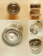 ZM1070
 - ZM1060 (Z505S) – Argon-filled, 50 kHz decade Counter/Selector Dekatron
- ZM1070 (Z504S, 8433) – Neon-filled, 5 kHz decade Counter/Selector Dekatron
- ZM1080 – ZM1082 with a red contrast filter coating
- ZM1081 – ZM1083 with a red contrast filter coating, for use with ZM1080
- ZM1082 – 0 1 2 3 4 5 6 7 8 9 Neon-filled digital indicator tube, 14mmCH side-viewing, no decimal point, probe electrode
- ZM1083 – + - ~ Neon-filled digital indicator tube, 14mmCH side-viewing, for use with ZM1082
- ZM1100 – 0 1 2 3 4 5 6 7 8 9 Neon-filled digital indicator tube, 15.5mmCH top-viewing
- ZM1120 – ZM1122 with a red contrast filter coating
- ZM1122 – 0 1 2 3 4 5 6 7 8 9 Miniature neon-filled digital indicator tube, 7.8mmCH top-viewing
- ZM1130 – ZM1132 with a red contrast filter coating
- ZM1131 – ZM1133 with a red contrast filter coating, for use with ZM1080
- ZM1132 – 0 1 2 3 4 5 6 7 8 9 Neon-filled digital indicator tube, side-viewing, left and right decimal point
- ZM1133 – + - ~ Neon-filled digital indicator tube, side-viewing, for use with ZM1132
- ZM1136L/R – ZM1138L/R with a red contrast filter coating
- ZM1137 – ZM1139 with a red contrast filter coating, for use with ZM1136L/R
- ZM1138L/R – 0 1 2 3 4 5 6 7 8 9 Neon-filled digital indicator tube, 13mmCH side-viewing, left or right decimal points (specify)
- ZM1139 – + - ~ Ω Neon-filled digital indicator tube, 13mmCH side-viewing, for use with ZM1138 in digital multimeters
- ZM1162 – 0 1 2 3 4 5 6 7 8 9 Long-life neon-filled digital indicator tube, 15.5mmCH top-viewing, no decimal point, rectangular envelope for close stacking in both axes
- ZM1170 – ZM1172 with a red contrast filter coating
- ZM1172 – 0 1 2 3 4 5 6 7 8 9 Neon-filled digital indicator tube, 15.5mmCH side-viewing, no decimal point
- ZM1174 – ZM1175 with a red contrast filter coating
- ZM1175 – 0 1 2 3 4 5 6 7 8 9 Neon-filled digital indicator tube, 15.5mmCH side-viewing, left decimal point
- ZM1176 – ZM1177 with a red contrast filter coating
- ZM1177 – ZM1175, but right decimal point
- ZM1180 – ZM1182 with a red contrast filter coating
- ZM1181 – ZM1183 with a red contrast filter coating, for use with ZM1180
- ZM1182 – 0 1 2 3 4 5 6 7 8 9 Neon-filled digital indicator tube, 16mmCH top-viewing, no decimal point, semi-rectangular envelope for close horizontal stacking
- ZM1183 – + - ~ Ω Neon-filled digital indicator tube, top-viewing, 13mmCH for use with ZM1182 in digital multimeters
- ZM1184D – ZM1185D with a red contrast filter coating
- ZM1185A (GR1420) – 1 2 3 4 5 6 U K E R Neon-filled digital indicator tube, 16mmCH top-viewing
- ZM1185D (GR1430) – ∇ Δ Neon-filled digital indicator tube, 16mmCH top-viewing, for use in elevators
- ZM1185E (GR1472) – 0 1 2 3 4 5 - t kg + Neon-filled digital indicator tube, 16mmCH top-viewing
- ZM1200 – Pandicon, multiplexed 14-digit display tube with decimal points and punctuation marks, pin connections on both ends
- ZM1202 – 12-Digit Pandicon
- ZM1204 – 10-Digit Pandicon
- ZM1206 – 8-Digit Pandicon
- ZM1210– ZM1212 with a red contrast filter coating
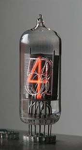 ZM1212
 - ZM1212 – 0 1 2 3 4 5 6 7 8 9 Neon-filled digital indicator tube, 15.5mmCH side-viewing, left decimal point, all-glass pigtailed
- ZM1220 – ZM1222 with a red contrast filter coating
- ZM1222 – 0 1 2 3 4 5 6 7 8 9 Large neon-filled digital indicator tube, 40mmCH side-viewing
- ZM1230 – ZM1232 with a red contrast filter coating
- ZM1232 – 0 1 2 3 4 5 6 7 8 9 Neon-filled digital indicator tube, 15.5mmCH upside-down side-viewing, no decimal point
- ZM1240 – ZM1242 with a red contrast filter coating
- ZM1241 – ZM1243 with a red contrast filter coating, for use with ZM1240
- ZM1242 – 0 1 2 3 4 5 6 7 8 9 Neon-filled digital indicator tube, 16mmCH side-viewing, right decimal point
- ZM1243 – + - ~ Ω Neon-filled digital indicator tube, 16mmCH side-viewing, for use with ZM1242 in digital multimeters
- ZM1263 – ~ ⚫ Neon-filled digital indicator tube, 10mmCH side-viewing
- ZM1290 – ZM1292 with a red contrast filter coating
- ZM1292 – 0 1 2 3 4 5 6 7 8 9 Neon-filled digital indicator tube, 10mmCH side-viewing
- ZM1330 – ZM1332 with a red contrast filter coating
- ZM1331 – ZM1333 with a red contrast filter coating, for use with ZM1330
- ZM1332 – 0 1 2 3 4 5 6 7 8 9 Neon-filled digital indicator tube, 13.1mmCH side-viewing, left and right decimal points, all-glass pigtailed
- ZM1333 – + - ~ Ω Neon-filled digital indicator tube, 13.1mmCH side-viewing, all-glass pigtailed, for use with ZM1332 in digital multimeters
- ZM1334 – ZM1336 with a red contrast filter coating
- ZM1335 – ZM1337 with a red contrast filter coating, for use with ZM1334
- ZM1336 – 0 1 2 3 4 5 6 7 8 9 Neon-filled digital indicator tube, 13.1mmCH side-viewing, left and right decimal points, multiplex-capable
- ZM1337 – + - ~ Ω Neon-filled digital indicator tube, 13.0mmCH side-viewing, right decimal point (!), all-glass pigtailed, red contrast filter coating, for use with ZM1336 in digital multimeters
- ZM1350 – Varisymbol, planar neon-filled digital 40mm x 27mm fourteen-segment display tube, right decimal point, separate underscore text cursor, keep-alive cathode, multiplex-capable, viewing angle 160°
- ZM1360 – ZM1350 with 60mm x 40mm characters
- ZM1370 – ZM1350 with 20mm x 13mm characters
- ZM1410 – ZM1412 with a red contrast filter coating
- ZM1412 – Neon-filled digital seven-segment display tube, 8.6mmCH side-viewing, right decimal point and left punctuation mark, all-glass pigtailed
- ZM1500 – Pandicon, multiplexed 12-digit, 7-segment display tube
- ZM1550 – Planar neon-filled digital two-digit seven-segment display tube, right decimal points
- ZM1551 – Planar neon-filled digital 1½-digit seven-segment display tube with + and - signs, right decimal points
Note: More Nixie tubes under standard - ZM and other letter - GR
ZP
- ZP1000 – Borium tri-fluoride-filled Geiger-Müller tube, thermal neutrons
- ZP1010 – Borium tri-fluoride-filled Geiger-Müller tube, thermal neutrons
- ZP1020 – Borium tri-fluoride-filled Geiger-Müller tube, thermal neutrons
- ZP1070 – Subminiature Geiger-Müller tube, all-glass pigtailed
- ZP1080 – Halogen-quenched Geiger-Müller tube, β and γ
- ZP1100 – Halogen-quenched Geiger-Müller tube, γ; pigtailed
- ZP1200 – Halogen-quenched Geiger-Müller tube, γ
- ZP1300 – Halogen-quenched Geiger-Müller tube, γ and high-energy β
- ZP1330 – Halogen-quenched Geiger-Müller tube, for use in damp and/or saline atmosphere, β and γ
- ZP1400 – Halogen-quenched Geiger-Müller tube, 9mm diameter mica window, β and γ
- ZP1430 – Halogen-quenched Geiger-Müller tube, 27.8mm diameter mica window, α, β, γ
- ZP1490 – Halogen-quenched Geiger-Müller tube, 28mm diameter mica window, low-level α, β and γ
- ZP1600 – Halogen-quenched Geiger-Müller tube, 19.8 mm diameter mica window, X-rays, 6.0 to 20 keV energy, 60 to 200 pm wavelength range
- ZP1610 – Side window, organically quenched Geiger-Müller tube. 7 x 18 mm mica window; X-rays, 2.5 to 40 keV energy, 30 to 500 pm wavelength range
- ZP1700 – Halogen-quenched, cosmic-ray guard counter tube for low-background measurements; to be used with another radiation counter tube in an anticoincidence circuit
- ZP1800 – Halogen-quenched Geiger-Müller tube for use at temperatures up to 200 °C, γ
- ZP1810 – Halogen-quenched Geiger-Müller tube for use at temperatures up to 200 °C, γ, low sensitivity, up to 40 mGy/h
- ZP1860 – Halogen-quenched Geiger-Müller tube, β and γ
ZT
- ZT1000 – 21 kV, 10 A Mercury vapor triode thyratron
ZX
- ZX1000 – 800 V, 1140 Apk, 13Aavg Ignitron
- ZX1051 – Water-cooled, 56 Aavg Ignitron
- ZX1052 – Water-cooled, 140 Aavg Ignitron
- ZX1053 – Water-cooled, 355 Aavg Ignitron
- ZX1060 – Water-cooled, 10 Aavg Ignitron
- ZX1061 – Water-cooled, 10 Aavg Ignitron
- ZX1062 – Water-cooled, 10 Aavg Ignitron
- ZX1063 – Water-cooled, 10 Aavg Ignitron
ZY
- ZY1000 (872B) – High voltage, half-wave mercury-vapor rectifier
- ZY1001/8008A – High voltage, half-wave mercury-vapor rectifier, 4-pin base with anode top cap
- ZY1002 – High voltage, half-wave mercury-vapor rectifier, E40 (Goliath) Edison screw lamp base with anode top cap
ZZ
- ZZ1000 – 81 V Voltage reference, 2-pin all-glass pigtailed
- ZZ1010 – 85 V Voltage reference
- ZZ1020 (STV85-8) – 82 V Voltage reference with primer electrode, 3-pin all-glass pigtailed
- ZZ1030 (STV500-0,1) – Quad 125 V Voltage references, noval base
- ZZ1031 – Quad Voltage reference, noval base
- ZZ1040 (STV100-60Z) – 100 V Voltage reference with primer electrode
- ZZ1050 – 82 V Voltage reference, 2-pin all-glass pigtailed
List of European transmitting tubes
Note: Typecode explained above.
B - Backward-wave amplifier
BA
- BA9/20 – X-band, 20 mW, Forced-air cooled backward-wave oscillator
D - Rectifier incl. grid-controlled
DA
- DA1.5/75 – 1.5 kV, 75 W Half-wave power rectifier, triode TA1.5/75 without grid
- DA12/24000 – 12 kV, 24 kW Water-cooled half-wave power rectifier
DC
- DC1/50 – 1 kV, 50 mA Full-wave power rectifier, DC1/60 with dual anode top cap
- DC1/60 – 1 kV, 60 mA Full-wave power rectifier
- DC2/200 – 2 kV, 200 mA Full-wave power rectifier with dual anode top cap
DCG
- DCG1/125 – 1 kV, 125 mA Half-wave mercury-vapor rectifier with Edison screw lamp base and anode top cap
- DCG12/30 – 12 kV, 30 A Grid-controlled, half-wave mercury-vapor rectifier with anode top cap
DCX
- DCX4/1000 – 4 kV, 1 kW Half-wave xenon rectifier with anode top cap
- DCX4/5000 – 4 kV, 5 kW Half-wave xenon rectifier with anode top cap
DE
- DE2/200 – 2 kV, 200 W Full-wave power rectifier with dual anode top cap
J - Magnetron
JP
- JP8/02B – 8.8 GHz, 25 W Magnetron
- JP9/15 – 9.345 to 9.405 GHz, 15 kW Forced-air cooled magnetron for pulsed service
JPT
- JPT9/01 – 9.15 to 9.60 GHz, 5 W Magnetron
K - Klystron
KB
KS
- KS7/85 – 6.5 to 7.5 GHz, 85 mW Reflex klystron
L - Traveling-wave tube
LA
- LA9/3 – 7 to 11.5 GHz Forward-wave amplifier
- LA16/2 – 11.5 to 18 GHz Forward-wave amplifier
M - AF modulator Triode
MA
- MA4/600 – 4 kV, 600 W Radiation-cooled triode
MB
- MB1/50 – 1 kV, 50 W Radiation-cooled triode
- MB2/200 – 2 kV, 200 W Radiation-cooled triode
MY
- MY3/275 – 3 kV, 275 W Radiation-cooled triode
MZ
- MZ2/200 – 2 kV, 200 W Radiation-cooled triode
P - Pentode
PA
- PA12/15 – 15 kW Water-cooled shortwave pentode
- PA12/20 – 20 kW Water-cooled pentode made by Philips and used in the 1930s and 1940s
PAL
- PAL12/15 – Air-cooled version of PAW12/15
PAW
- PAW12/15 – 15 kW Water-cooled shortwave pentode
PB
- PB2/200 – 200 W Shortwave pentode
- PB3/1000 – 1 kW Shortwave pentode
PC
- PC03/3 – 3 W Shortwave pentode
- PC3/1000 – 1 kW Shortwave pentode
PE
- PE04/10 – 10 W Shortwave pentode
- PE1/100 (YL1200) – 100 W Shortwave pentode
Q - Tetrode
QB
- QB2/75 – 75 W Beam-tetrode
- QB5/2000 – 2 kW Beam-tetrode
QBL
- QBL4/800 – Air-cooled 800 W beam-tetrode
- QBL5/3500 – Air-cooled 3500 W beam-tetrode
QBW
- QBW5/3500 – Water-cooled 3500 W beam-tetrode
QC
- QC05/15 – 15 W Beam-tetrode
- QC05/35 – 35 kW Beam-tetrode
QE
- QE04/10 – 10 W Beam-tetrode
- QE05/40 (6146) – 40 W Radiation-cooled output beam-tetrode, popular amongst radio amateurs as a final RF amplifier
- QE08/200 – 200 W Beam-tetrode
QEL
- QEL1/150 – Air-cooled 150 W beam-tetrode
- QEL1/250 – Air-cooled 250 W beam-tetrode
QEP
- QEP20/18 – 18 W Beam-tetrode for use as a pulse modulator
QQC
- QQC03/14 – 14 W Dual beam-tetrode
QQE
- QQE02/5 (6939) – 5 W Dual beam-tetrode
- QQE03/12 (6360) – 12 W Dual beam-tetrode
- QQE03/20 (6252) – 20 W Dual beam-tetrode
- QQE04/5 (7377) – 5 W Dual beam-tetrode
- QQE06/40 (5894, YL1060) – 40 W dual beam-tetrode, internally neutralized, Septar base with dual anode top cap
QQV
- QQV02/6 – 6 W dual beam-tetrode
- QQV03/20A – 20 W Radiation-cooled split-anode tetrode made by Mullard and used in the 1940s, 1950s and 1960s as a VHF frequency-doubling output stage with balanced output.
- QQV07/50 – 50 W Dual beam-tetrode
QQZ
- QQZ03/20 (8118, YL1020) – 20 W Dual beam-tetrode
- QQZ06/40 (YL1030) – 40 W Dual beam-tetrode
QV
- QV04/7 – 7 W Beam-tetrode
- QV05/25 (807) – 25 W Radiation-cooled output beam-tetrode made by Mullard.
- QV2/250C – 250 W Beam-tetrode
QY
- QY3/65 – 65 W Beam-tetrode
- QY5/3000A – 3 kW Beam-tetrode
- QY5/3000W – Water-cooled version of QY5-3000A
QYS
- QYS50/P40 – Pulsed power tetrode, Silica envelope, 50 kV anode voltage, considerable x-radiation, 810 °C anode temperature at 700 W anode dissipation, 40 A anode current at duty factor 0.0005, Vg1Cut-off (IA=1 mA@VA=55 kV): > -3.4 kV, gm: 38 mS
QZ
- QZ06/20 – 25 W VHF Power tetrode up to 175 MHz
R - Rectifier
RG
- RG1000/3000 – 1 kV, 3 A Half-wave mercury-vapor rectifier with anode top cap
RGQ
- RGQ7.5/0.6 – 7.5 kV, 600 mA Half-wave mercury-vapor rectifier with anode top cap
- RGQ20/5 – 20 kV, 5 A Half-wave mercury-vapor rectifier with anode top cap
T - AF/RF/oscillator Triode
TA
- TA04/5 – 400 V, 50 W Radiation-cooled power triode
- TA1.5/75 – 1.5 kV, 75 W Radiation-cooled power triode
- TA4/2000K – 4 kV, 2 kW Air-cooled power triode made by Philips in the 1930s
- TA18/100000 – 18 kV, 100 kW Water-cooled power triode
TB
- TB04/8 – Directly heated Doorknob VHF power triode up to 600 MHz
- TB2.5/400 – 2.5 kV, 300 W Radiation-cooled power triode
- TB5/2500 – 5 kV, 2.5 kW Radiation-cooled power triode
TBL
- TBL2/300 – 2 kV, 300 W Forced air-cooled power triode
- TBL15/125 – 15 kV, 125 kW Forced air-cooled power triode
TBW
- TBW6/14 – 6 kV, 14 kW Water-cooled power triode
- TBW15/125 – 15 kV, 125 kW Water-cooled power triode
TC
- TC03/5 – RF power triode up to 85 MHz, 5 W
- TC2/250 – RF power triode up to 20 MHz, 250 W
TD
- TD03/5 – Indirectly heated disk-seal UHF power triode up to 2 GHz
- TD03/10 – Indirectly heated disk-seal UHF power triode up to 2.8 W, 3.75 GHz
- TD03/10F – TD03/10 with internal feedback for use as an oscillator
- TD04/20 – Indirectly heated disk-seal UHF power triode up to 13.5 W, 1 GHz
- TD1/100C = 2C39BA – Indirectly heated, ceramic disk-seal UHF power triode up to 24 W, 3.5 GHz[142]
- TD2/400 – Directly heated, ceramic disk-seal UHF power triode up to 600 W, 900 MHz
- TD2/500 – Directly heated, ceramic disk-seal UHF power triode up to 500 W, 940 MHz
TE
- TE05/10 – RF power triode up to 150 MHz
TX
- TX12/12W – Water-cooled RF power triode
- TX12/20W – Water-cooled RF power triode
- TX10/4000 – Power triode, Silica envelope, 12 kV anode voltage, 4 kW anode dissipation, 1.6 A cathode current, gm: 4.5 mS, for use as self-excited high-power oscillator in induction heating equipment.
TY
- TY2/125 – 135 W VHF power triode up to 200 MHz
- TY12/50A – Forced-air cooled 45 kW RF power triode up to 30 MHz
- TY12/50W – Water-cooled 50 kW RF power triode up to 30 MHz
TYS
- TYS2/250 – Power triode, Silica envelope, 2.5 kV anode voltage, 250 W anode dissipation
- TYS4/500 – Power triode, Silica envelope
- TYS5/1000 – Power triode, Silica envelope
- TYS5/2000 – Power triode, Silica envelope
- TYS5/3000 – Power triode, Silica envelope, 6 kV anode voltage, 950 °C anode temperature at 3.5 kW anode dissipation, 2.8 A cathode current, gm: 15 mS. Used in RF generators for induction hardening.
X - Thyratron
XGQ
- XGQ2/6400 – 2 kV, 6.4 kW Mercury-vapor tetrode thyratron with anode and grid1 top caps
XR
- XR1/1600 (5545) – 1 kV, 1.6 kW Inert gas-filled triode thyratron with anode top cap
- XR1/6400 – 1 kV, 6.4 kW Inert gas-filled triode thyratron with anode top cap
List of other letter tubes
A
Edison and Swan Electric Light Company (British Mazda/EdiSwan):
- A40 – Acorn UHF triode up to 600 MHz, 4 Volts heater
- A41 – Acorn UHF pentode up to 600 MHz, 4 Volts heater
AC*/
Mazda/EdiSwan 4-volts AC, indirectly heated receiver tubes:
- AC/HL – AF triode, British 5-pin base
- AC/HLDD = TDD4 = MHD4 – Dual diode and AF triode, British 7-pin base
- AC/ME – Tuning indicator, British 7-pin base
- AC/P, AC/P1 – AF triode, British 5-pin base
- AC/P4 – CRT electrostatic-deflection output power triode, British 5-pin base
- AC/PEN – AF power pentode, British 7-pin base
- AC/S2PEN – RF pentode, British 7-pin base
- AC/SP1 – RF pentode for use in squelch circuits or, as the reactance tube, in AFC circuits, British 7-pin base
- AC/SP3 – RF pentode for shortwave and TV receivers, British 7-pin base
- AC/SP3/RH – Low-noise, low-microphonics RF pentode for shortwave and TV receivers, British 7-pin base
- AC/TH1 – Triode/hexode oscillator/mixer, British 9-pin base
- AC/TP = TP4 – Triode/pentode oscillator/mixer, British 7-pin base
- AC/VP1, AC/VP2 – RF pentode, British 7-pin base
- AC2/HL – High-mu triode
- AC2/PEN – AF Power pentode
- AC2/PEN.DD – Dual diode and AF Power pentode
- AC4/PEN – AF Beam power pentode
- AC5/PEN – AF Beam power pentode
- AC5/PEN.DD – Dual diode and AF Beam power pentode
- AC6/PEN – Beam power pentode for use as a magnetic horizontal-deflection output amplifier
ACT
- ACT9 – 800 W Air cooled transmitting triode up to 15 MHz, with derating up to 80 MHz
AP
AT
- AT4 = 4675 – Acorn UHF triode up to 430 MHz, 4 Volts heater
B
BA
Industrial Electronics Engineers:
- BA-0000-P31 – Nimo tube, cathode-ray 1-digit numeric display tube, 10 stenciled electron guns aiming at a P31-phosphor (green, medium-persistence) fluorescent screen, top-viewing, Futura Medium font, 2.5 kV anode voltage, 12-pin base
BG
- BG08220-K – Neon-filled, planar, base-24 display dekatron with four sets of guiding cathodes and a carry/borrow cathode, for use e.g. in direction-finding equipment
BT
British Thomson-Houston (General Electric subsidiary):
- BT1 – Thyratron used in Wynn-Williams' binary prescaler for the alpha particle counter that Rutherford, Chadwick et al. used for their nuclear research at the Cavendish Laboratory in the 1930s[143]
C
CH
- CH1027 – Curristor – Four types of nitrogen-filled, radioactive constant-current tubes with a current plateau from 25 to 500 V, all-glass pigtailed, active material is 226Ra with a half-life of 1601 years, for linear capacitor charging and draining in missile and ordnance mine timing circuits, instrumentation biasing, as current reference, etc.:
CK
| H | I | ? | . | ¤ | [ | < | ⊞ |
| + | A | B | C | D | E | F | G |
| Q | R | ! | $ | * | ] | ; | △ |
| - | J | K | L | M | N | O | P |
| Y | Z | = | , | % | ≶ | ' | ⊠ |
| / | S | T | U | V | W | X | |
| 8 | 9 | 0 | # | @ | : | > | ■ |
| 1 | 2 | 3 | 4 | 5 | 6 | 7 |
- CK1022 – 1 kV/5...55 µA Corona voltage reference, miniature 7-pin base with anode top cap
- CK1037 = 6437 – 700 V/5...125 µA Corona voltage reference, 3-pin all-glass pigtailed
- CK1038 – 900 V/5...55 µA Corona voltage reference, 3-pin all-glass pigtailed
- CK1039 = 6438 – 1.2 kV/5...125 µA Corona voltage reference, 3-pin all-glass pigtailed
- CK1366, CK1367, CK1368, CK1369 – CRTs with an unphosphored front glass but with fine wires embedded in it for use as electrostatic print heads; the wires would pass the electron beam current through the glass onto a sheet of paper where the desired content was therefore deposited as an electrical charge pattern. The paper was then passed near a pool of liquid ink with the opposite charge. The charged areas of the paper attract the ink and thus form the image.[144][145]
- CK1383 – Dual-electron gun recording storage tube, a realtime polar, radar PPI-to-rectangular, TV-type analog video transcoder similar to the 7702, with simultaneous R/W, and storing capability. This was achieved by a CRT/camera tube combination; the CRT part writes the PPI-format image onto a thin, dielectric target; the camera part reads the generated charge pattern in TV format from the back side of this target.[146]
- CK1414 – Symbolray character generator monoscope for text mode video rendering in early computer monitors, with a square target having letters, digits and symbols patterned on it in a customer-supplied 8x8 or 8x12 array. An electron beam selects and scans a character, both by appropriate electrostatic deflection, and generates an analog video signal;[147][148] cf. 4560, TH9503
CL
- CL40 and CL41 – Indirectly heated, linear light source (glow modulator tube), mercury/argon-filled gas diode with primer electrode, 8-pin base, for rotating-drum FAX receivers, film soundtrack recording, etc.
- CL42 and CL43 – Indirectly heated, low-noise linear light source, helium-filled gas diode with primer electrode, 8-pin base, for film soundtrack recording, interferometers, etc.
- CL44 – Indirectly heated, low-noise linear light source, neon-filled gas diode with primer electrode, 8-pin base
- CL50 and CL52 – Indirectly heated, linear light source, gas-filled diode with primer electrode, 7-pin base, for rotating-drum FAX receivers, film soundtrack recording, etc.
- CL55 – Indirectly heated, spectrally pure light source, helium-filled gas diode with primer electrode, 7-pin base with anode top cap
- CL56 – Indirectly heated, spectrally pure light source, krypton-filled gas diode with primer electrode, 7-pin base with anode top cap
- CL57 – Indirectly heated, spectrally pure light source, neon-filled gas diode with primer electrode, 7-pin base with anode top cap
- CL58 – Indirectly heated, spectrally pure light source, xenon-filled gas diode with primer electrode, 7-pin base with anode top cap
- CL60 – Indirectly heated triode flood beam CRT-type stroboscope lamp with a green A-type phosphor with <1 μs decay time and 10 kCd light output, 20 kV anode voltage, 7-pin duodecal base
- CL61 – CL60 with a blue P-type phosphor with 5 μs decay time and 16 kCd light output
- CL62 – CL60 with an UV Q-type phosphor with 100 ns decay time and 240 Cd light output
- CL63 – CL60 with a yellow-green C-type phosphor with 6 μs decay time and 24 kCd light output
- CL64 – CL60 with a yellow V-type phosphor with 5 μs decay time and 12 kCd light output
- CL65 – CL60 with a red R-type phosphor with 2 μs decay time and 14 kCd light output
- CL66 – CL60 with a white T-type phosphor with 5 μs decay time and 12 kCd light output
D
- D1 – Early directly heated triode used in 1920s TRF and regenerative radios
DDR
- DDR100 – 100 g max., 250 Hz max., 1-axis accelerometer double diode with elastically supported anodes, 6.3V/600mA indirect heater, fres = 1 kHz, B8G base[149]
DZ
Cerberus:
- DZ10 – 3 kHz max. Decade Counter/Selector Dekatron, 14-pin diheptal base
E
EN
- EN10 – Neostron, 400 Apk Gas-filled, cold-cathode tetrode thyratron, differential trigger electrodes, 8-pin base, for use as a relay or as a reddish 700 Cd stroboscope lamp
- EN15 – 80 Aavg Neon-filled, cold-cathode tetrode thyratron, differential trigger electrodes, miniature 9-pin base, for use as a stroboscope lamp
- EN30 – 250 Apk Gas-filled, arc-discharge cold-cathode tetrode thyratron, differential trigger electrodes, miniature 7-pin base with anode cap, for use as a relay or as a stroboscope lamp
- EN40 – 250 Apk Gas-filled, cold-cathode tetrode thyratron, differential trigger electrodes, 8-pin base, for use as a whitish stroboscope lamp with a high actinism for photographic film
- EN55 Single, EDN10 dual xenon-filled, arc-discharge cold-cathode tetrode thyratron, external (capacitive) trigger, 12-pin base, for use as a white 140 kCd stroboscope lamp
- EN60 – Gas-filled, arc-discharge cold-cathode tetrode thyratron, external (capacitive) trigger, Edison screw lamp base with anode cap, for use as a white 900 klm@10µF@800V stroboscope lamp
G
Standard Telephones and Cables/Brimar:
- G10/241E – Nomotron, an unidirectional Dekatron with multi-alloy cathodes
Cerberus:
- G11 – 5 mA Gas-filled, cold-cathode switching diode e.g. for relaxation oscillators, 2-pin all-glass pigtailed
- G42 – 35 mApeak Gas-filled switching diode e.g. for relaxation oscillators, 2-pin all-glass pigtailed
GC
- GC10/2P – Neon-filled, 1 kHz Miniature decade Counter Dekatron, a gas-filled, bidirecional decade counter tube
- GC10A – Helium-filled, decade Counter Dekatron
- GC10B – Neon-filled, 4 kHz Long life, decade Counter Dekatron
- GC10/4B – 4 kHz Decade Computing Counter Dekatron with carry/borrow cathodes "0" and "9" and intermediate cathodes "3" and "5" wired to separate pins
- GC10D – 20 kHz Decade Counter Dekatron, for single-pulse operation
- GC12/4B – 4 kHz Duodecimal Counter Dekatron with carry/borrow cathodes 11 and 12 and intermediate cathodes 6 and 8 wired to separate pins
GCA
- GCA10G – 10 kHz max. Decade Counter Dekatron with routing guides and aux anodes to directly drive Nixie tubes, B27A base without the inner pin ring
GD
- GD2V – 2 kV, 16 J discharge tube, all-glass studded
- GD75P – 75 V Voltage reference, miniature 7-pin base
- GD90M – 90 V Voltage reference, miniature 7-pin base
- GD340X – 345 V/3...200 µA Corona voltage reference, all-glass pigtailed
- GD350X, GD350Y – 350 V/3...200 µA Corona voltage reference, all-glass pigtailed
- GD550W – 550 V, 1.5 J Discharge tube, e.g. for power relaxation oscillators, all-glass pigtailed
GDT
- GDT120M – 9 mA Gas-filled cold-cathode DC triode, one starter and a separate glow diode acting as an optical primer, miniature 7-pin base
GE
- GE10 – Directly heated saturated-emission diode. Acts as a heating current-controlled, variable series resistor in voltage/current stabilizer circuits. It has two shorted pins that can be used to disable the circuit if the tube is removed from its socket
GK
Cerberus:
- GK11 – Touch button tube, an illuminated capacitance touch switch; a cold-cathode DC relay tube, external (capacitive) starter activated by touching; then the cathode glow is visible as an orange ring. 2-pin all-glass pigtailed
GN
- GN10 – 250 Amps pulse-current, cold-cathode tetrode thyratron. Octal base
GR
- GR2G – + - Neon-filled digital indicator tube, 18 x 18 mm characters, side-viewing
- GR2H – + - Neon-filled digital indicator tube, 20 x 20 mm characters, top-viewing
- GR4G – ¼ ½ ¾ 1 Neon-filled digital indicator tube, 18 x 30 mm characters, side-viewing
- GR7M – + - V A Ω % ~ Neon-filled digital indicator tube, 15.5 mm character height, top-viewing
- GR10A – Gas-filled digital indicator tube with a dekatron-type readout
- GR10G – 0 1 2 3 4 5 6 7 8 9 Neon-filled digital indicator tube, 16.86 x 30 mm characters, side-viewing
- GR10H – 0 1 2 3 4 5 6 7 8 9 Neon-filled digital indicator tube, 12 x 19 mm characters, top-viewing
- GR10J – 0 1 2 3 4 5 6 7 8 9 Neon-filled digital indicator tube, 16.86 x 30 mm characters, side-viewing
- GR10K – 0 1 2 3 4 5 6 7 8 9 Neon-filled digital indicator tube, 12 x 19 mm characters, top-viewing
- GR10M – 0 1 2 3 4 5 6 7 8 9 Neon-filled digital indicator tube, 10 x 15.5 mm characters, top-viewing
- GR10W – 0 1 2 3 4 5 6 7 8 9 Neon-filled digital indicator tube, 8.42 x 15 mm characters, side-viewing, all-glass pigtailed
- GR12G – A B C D E F G H I J K L Neon-filled digital indicator tube, 16 x 30 mm characters, side-viewing
- GR12H – E L M N P R S T U V W X Neon-filled digital indicator tube, 16 x 30 mm characters, side-viewing
Note: More Nixie tubes under standard - ZM and professional - ZM
Cerberus:
- GR15 – 15 mA Gas-filled cold-cathode DC tetrode, one starter and one electrical primer and tritium-primed (half-life: 12.32 years), noval base, for voltage triggers, RC timers etc.
- GR16 – 20 mA Gas-filled, cold-cathode, tritium-primed AC/DC triode, one starter and an EM shield, noval base, for voltage triggers, RC timers etc.
- GR17 – 15 mA Gas-filled cold-cathode AC triode, one starter and an EM shield, noval base, for voltage triggers, RC timers etc.
- GR31 – 15 mA Gas-filled cold-cathode DC tetrode, one starter and one electrical primer plus a tritium primer, noval base
- GR44 – 12 mA Subminiature gas-filled cold-cathode DC pentode, two starters and one primer electrode plus a tritium primer, 5-pin all-glass pigtailed
- GR46 – 12 mA Subminiature gas-filled cold-cathode DC tetrode, one starter and one primer electrode, 4-pin all-glass pigtailed
GRD
- GRD7 – Educational, directly heated saturated-emission guard ring diode
GS
- GS10C – 4 kHz max. Decade Counter/Selector Dekatron, top-viewing, duodecal base
- GS10D – Hydrogen-filled, 20 kHz max. Decade Counter/Selector Dekatron, duodecal base
- GS10H – 4 kHz max. Decade Counter/Selector Dekatron with routing guides, B17A base
- GS12C – 4 kHz max. Duodecimal Counter/Selector Dekatron, with solder lugs
- GS12D – Neon-filled, 4 kHz max. duodecimal Counter/Selector Dekatron, duodecal base with two additional pigtails for the guide electrodes
GSA
- GSA10G – 10 kHz max. Decade Counter/Selector Dekatron with routing guides and aux anodes to directly drive Nixie tubes, B27A base
GTE
- GTE120Y – 5 mA Subminiature DC trigger tetrode, one starter and one primer, all-glass pigtailed
- GTE130T – 8 mApeak DC trigger tetrode, one starter and one primer, close tolerance, low aging, quadrant I operation only, noval base
- GTE175M – 3.5 mAavg, 50 mApeak DC Trigger tetrode, one starter and one primer, miniature 7-pin base, for Dekatron coupling circuits
GTR
- GTR120W – 9 mA Subminiature DC trigger triode, 3-pin all-glass pigtailed, for computer applications
- GTR75M – 75 V Voltage reference, Miniature 7-pin
- GTR95M/S – 95 V Voltage reference, Miniature 7-pin
- GTR150 – Subminiature, primed 150 V voltage reference, all-glass pigtailed
K
KN
Edgerton, Germeshausen, and Grier:
- KN2 – 4 kV, 500 Asurge Krytron, a cold-cathode gas-filled tube with a primer electrode, for use as a very high-speed, high-surge current switch; similar to a thyratron, lifespan 107 shots, 4-pin all-glass pigtailed[150]
- KN4 – 5 kV, 2.5 kAsurge Krytron with a primer electrode, lifespan 25000 shots, 4-pin all-glass pigtailed
- KN6 – 5 kV, 3 kAsurge Krytron with a primer electrode, lifespan 35000 shots, 4-pin all-glass pigtailed
- KN6B – 8 kV, 3 kAsurge Krytron with a primer electrode, lifespan 35000 shots, 4-pin all-glass pigtailed
- KN9 – 4 kV, 500 Asurge Krytron with a primer electrode, lifespan 1.5⋅107 shots, 4-pin all-glass pigtailed
- KN11B – 2.5 kV, 1.5 kAsurge Sprytron, lifespan 2000 shots, 3-pin all-glass pigtailed
- KN12 – 5 kV, 3 kAsurge Sprytron, lifespan 500 shots, 3-pin all-glass pigtailed
- KN22 – 5 kV, 100 Asurge Krytron with a primer electrode, lifespan 2⋅107 shots, 4-pin all-glass pigtailed, for laser pumping, to drive Pockels cells, also for educational purposes[151]
- KN26 – 5 kV, 3 kAsurge Krytron with a primer electrode, lifespan 75000 shots, 4-pin all-glass pigtailed
KT
Marconi-Osram Kinkless Tetrode beam power tubes
- KT32 (25L6, 25L6G, 25L6GT and 25W6GT)
- KT33 (25A6GT)
- KT41
- KT61 (6M6G) in parallel filament circuits
- KT63 (6F6, 6F6G, 6F6GT)
- KT66 (6L6GC)
- KT67 – Small transmitting valve
- KT71 (50L6GT)
- KT77 – Similar to EL34, 6CA7
- KT81
- KT88 = 6550A = CV5220 (12E13, 7D11) – AF beam power tube, two tubes are capable of providing 100W output, Class-AB1, octal base
- KT90
- KT120 – New production tube
- KT150 – New production tube
M
M8000s
UK Military developed:
- M8083 – Sharp-cutoff pentode, miniature 7-pin base (SQ version of EF91 = 6AM6 = Z77)
- M8162 = 6060 – High-mu dual triode, for use as RF amplifier/mixer in VHF circuits, noval base (SQ version of ECC81 = 12AT7 = B309)
MC
- MC6-16, MC13-16 – CRT-type flying-spot scanners, P16-type phosphor (violet/near-ultraviolet, very short persistence), for use in a telecine
ME
Edison and Swan Electric Light Company (British Mazda/EdiSwan):
- ME91 – AC/DC mains tuning indicator
P
PBG
Dale:
- PBG12201 – Neon-filled, planar, dual 200-segment linear glow-transfer bar graph display tube with three cathode strings,[152] for use in VU meters etc.; cf. BG08220-K
- PBG12203 – Neon-filled, planar, dual 201-segment linear glow-transfer bar graph display tube with three cathode strings, for use in VU meters etc.
- PBG12205 – Neon-filled, planar, dual 200-segment linear glow-transfer bar graph display tube with five cathode strings, for use in VU meters etc.
- PBG16101 – Neon-filled, planar, dual 101-segment linear glow-transfer bar graph display tube with three cathode strings, for use in VU meters etc.; similar to ИН-33
PD
Edison and Swan Electric Light Company (British Mazda/EdiSwan):
- PD220 – Dual AF power triode for battery-supplied equipment (1939)
PL
- PL21 = 2D21 = EN91 – 100 mAavg, 500 mApeak, 10 Asurge, Gas-filled, indirectly heated tetrode thyratron, negative starter voltage, miniature 7-pin base, for relay and grid-controlled rectifier service
- PL323 = 3C23 – 1.5 Aavg, 6 Apeak, Mercury-vapor triode thyratron, 4-pin base with anode top cap
- PL5727 = 5727 – 100 mAavg, 500 mApeak, 10 Asurge, Tetrode thyratron, 7-pin miniature base
Q
- Q13-110GU – CRT-type flying-spot scanner, white phosphor, for use in a telecine
QK
- QK329 – Beam-deflection square-law tube for use as a function generator in analog computers. A flat sheet beam is electrostatically deflected across the anode which is partially covered by a parabolically stenciled screen "grid" that acts as the tube's output. Two tubes may be combined to form a 1-quadrant analog multiplier using the equation a⋅b = (a+b)2 − (a−b)2/4 where the deflection electrode signals a+b and a−b can be obtained directly from a fully balanced resistor bridge[153]
R
- R – Early directly heated triode derived from the French TM tube and used by many amateurs in the 1920s[154][155][156]
RK
- RK61 – Miniature, gas-filled, directly heated thyratron designed specifically to operate like a vacuum triode below its ignition voltage, allowing it to both amplify analog signals and work as a relaxation oscillator, for use as a self-quenching superregenreative detector up tp 100 MHz in radio control receivers, activating a relay in its anode circuit when a carrier wave is received; 4-pin all-glass pigtailed, 1.4 V, 45 mA filament, Ua=45 V, Ia=1.5 mA.[157]
- RK62 – RK61's predecessor, marketed since 1938;[158] this was the major technical development which led to the wartime development of radio-controlled weapons and the parallel development of radio controlled modelling as a hobby.[159]
S
SB
- SB256 – 256-bit Selectron tube, an early form of digital computer memory[160][161]
SU
- SU25 – EHT rectifier
- SU2150 (CV1120) – High-voltage vacuum half-wave rectifier for use in CRT power supplies
T
British General Electric Company:
- TuneOn – Early neon-filled bar graph tuning indicator, a glass tube with a short wire anode and a long wire cathode that glows partially; the glow length is proportional to the tube current[162]
- TuneOn Button – Early glow modulator used as a budget-priced tuning indicator – a neon lamp whose brightness is proportional to the tube current[163]
Standard Telephones and Cables/Brimar:
- Tunograph – Precursor of the "Magic Eye" tuning indicator first introduced in 1933; a tiny CRT with 1-axis electrostatic deflection and a phosphored target at 45° to the electron beam, so the projected green dot can be observed from the side[164]
TH
Compagnie Française Thomson-Houston:
- TH9503 – Scripticon, a character generator monoscope for text mode video rendering in early computer monitors, with a square target having letters, digits and symbols patterned on it in an (optionally customer-supplied) 8x8 array. An electron beam selects and scans a character, both by appropriate magnetic deflection, and generates an analog video signal;[165] cf. 4560, CK1414
TM

E.C.&A. Grammont and Compagnie des Lampes (1888):
- TM – Vacuum triode for amplification and detection of radio signals, developed in France and made since 1915.[166][167][168][169] It became the standard receiving and amplifying tube of the Entente countries during World War I, and the first mass-produced radio tube. TM's production volume in France alone is estimated at 1.1 million units; in addition, the production of TM and/or improved versions was started in the UK (Marconi–Osram R tube), the Netherlands (Philips E tube), the United States and the Soviet Union (R-5, Russian: Р-5).(ru)
- The TM was developed in 1914–15 by the French military telecommunications service Télégraphie Militaire on the initiative of their technical director Gustave-Auguste Ferrié. He and his assistant, physicist Henri Abraham, visited the American laboratories on a number of occasions and were aware of the works of Lee de Forest, Reginald A. Fessenden and Irving Langmuir. They knew that de Forest's Audion and Henry Round's British tube were unreliable and imperfect, and Langmuir's Pliotron was too complex for mass production. They also knew about the latest German developments: Soon after the outbreak of the war, Ferrié received extensive information from a former Telefunken employee, the Frenchman Paul Pichon, who, upon return from a mission from his German employer to gather samples of the latest triodes from the USA, had to surrender himself and the samples to the French. The samples Pichon brought performed poorly due to insufficient vacuum. Following the ideas of Langmuir, Ferrié required the industry to guarantee a high vacuum in series production.
- In October 1914, Ferrié, Abraham and François Péri from the radiotelegraph centre in Lyon/La-Doua(fr) went to the light bulb department of Société des Téléphones E.C.&Alexandre Grammont in Lyon to develop with them a triode suitable for mass production. The first prototypes, mere copies of de Forest's Audion, proved to be unreliable and unstable; the next ones were rejected for being too complex. Only the fourth prototype developed in December 1914, with a vertical coaxial system, an Edison screw lamp base for the filament and additional side terminals for anode and grid, was deemed suitable for series production, which started in February 1915 and stopped in October 1915 when it became clear that the vertical structure of "Abraham's Lamp" was too fragile and too many tubes were damaged during transport. Ferrié asked Péri to resolve the problem, and two days later Péri and Jacques Biguet came up with a horizontal coaxial system on the latest four-pin type "A" base. The series production of the Péri/Biguet tubes, named TM after Ferrié's service unit, began in November 1915 under Grammont's Radio Fotos brand; this variant became highly successful, and when demand started to exceed Grammont's production capacity, Compagnie des Lampes (1888) in Ivry-sur-Seine also started production under their Métal brand. Ferrié and Abraham were nominated for the 1916 Nobel Prize in Physics for their work in the field of radio communications.
- The TM is a cylindrical/coaxial triode; the directly-heated cathode is a filament made of pure tungsten with a diameter of 60 μm, the anode is a nickel cylinder with a diameter of 10 mm and a length of 15 mm. The dimensions and material of the grid depend on the place of production – the Grammont plant in Lyon used molybdenum wire, the CdL plant in Ivry-sur-Seine used nickel. The diameter of the grid spiral is 4 resp. 4.5 mm. The filament required 4 V and 700 mA to bring it up to white heat; the bright glow prompted Grammont in 1923 to start producing TM tubes with dark blue glass envelopes to protect the eyes of radio operators from the blinding glare, and hide the harmless, but unsightly plaque of metal particles inevitably deposited on the inner wall of the bulb while evacuating during production – but also prevented the triodes' previous, secondary use as light sources, which had earned them their nickname Loupiote ("little lamp").
- The TM could be used for their intended purpose, amplifying and detecting signals in radio receivers, or as power oscillators in low-power radio transmitters, and also, by paralleling of several tubes, as AF power amplifiers. The Soviet analogue of the TM, the triode R-5, could withstand anode voltages of up to 500...800 V, and was able to deliver a power of up to 1 W in Class-C mode, but only 40 mW in Class-A mode. A typical single-TM radio receiver of World War I ran at Ua=40 V, Ug=0 V, Ia≈2 mA, gm=400 μS, Ri=25 kΩ, μ=10. With an anode voltage of 160 V and a grid bias of -2 V, the anode current was 3...6 mA, while the reverse grid current reached 1 μA.[170]
- The problem of TM tubes was their short service life of 100 hours maximum – if the tube was manufactured in strict accordance with the specifications. In wartime, this was not always possible; due to raw materials supply problems, plants sometimes had to use substandard materials. Such tubes were marked with a cross; they differed from the standard by a higher noise level and were prone to catastrophic failures due to cracks in the glass envelope.
TT
- TT8, TT9, TT13, TT15, TT17, TT18, TT20, TT21, TT22 – Chronotron, integrating, balanced-bridge hot-wire/PTC time delay devices
- TT11 – Low power VHF transmitting beam tetrode
- TT21 – RF power beam-tetrode derived from KT88
- TT100 – RF power beam-tetrode
V
VHT
- VHT1 – Pentagrid converter, 1933
VS
- VS10G – Trochotron, an electron-beam decade counter tube
- VS10G-M – VS10G with a magnetic shield
- VS10H – High-current trochotron
- VS10K – Low-voltage trochotron
List of other number tubes
1
- 175HQ – Ultra high reliability pentode for use in long-haul submarine communications cable repeaters[171]
1600s
- 1602 – Directly heated triode used for A.F. amplification with low microphonics. 7.5 volt heater/filament. 12 watts of A.F. operating in Class-A. 15 watts of low R.F. operating in Class-C. Similar to type 10.
- 1603 – Indirectly heated pentode used for A.F. amplification with low microphonics. Similar to types 6U7, 57, 6D6 and 6C6. UX6 Base.
- 1608 – Directly heated triode giving 20 watts at up to 45 MHz. 2.5 volt heater/filament. UX base.
- 1609 – Directly heated pentode used for A.F. amplification with low microphonics. American 5-Pin(UY)base.
- 1610 – Directly heated pentode specially designed for use as a crystal oscillator. 2.5 volt heater/filament, American 5-Pin base.
- 1612 – Pentagrid converter; low-microphonics version of type 6L7. Both control grids (1 and 3) are sharp-cutoff.
- 1619 – Beam Power Tetrode, similar to 6L6 with directly heated filament, common in World War II battle tank transmitters.
- 1624, 1625 – Very similar to the 807, but with different heater voltage
- 1626 – RF triode, very similar to 6J5 but with 12.6 volt filament
- 1629 – Tuning indicator tube with DC amplifier triode unit
- 1630 – Indirectly heated, orbital-beam, secondary-emission, 12-pin Jumbo Acorn-type UHF hexode
- 1633 – Dual triode, equivalent to 6SN7 with 26 volt filament (World War II aircraft use)
- 1635 – Indirectly heated, 10.4 W dual AF power triode, 8-pin base
- 1636 – Secondary emission UHF beam deflection tube, used as a balanced mixer up to 600 MHz[172]
- 1650 – High-altitude version of the 955 Acorn-type triode
- 1680 – Dual-control heptode for use as a NAND gate in a coincidence circuit in IBM computers, 6BE6/EK90 with a sharp-cutoff grid no.3
2
- 24B1 – Trigatron
- 24B9 – Trigatron
- 29C1 – Directly heated saturated-emission diode; acts as a heating current-controlled, variable series resistor in voltage/current stabilizer circuits.
200s
- 203A – 40 W, Directly heated RF transmitter power triode, 4-pin base, anode on top cap
- 204A – 450 W, Directly heated RF transmitter power triode, 3-pin base, anode on top cap
- 205D – 1 W, Directly heated AF or modulator power triode, 4-pin base
- 207 – 22.5 kW, Water-cooled, directly heated RF transmitter power triode
- 210T – Directly heated RF transmitter power triode, 4-pin base, similar to type 10 triode with an isolantite base
- 210DET – Cossor directly heated, 2 volts, special detector
- 210HF – Cossor, directly heated, 2 volts, triode
- 210HL – Cossor, directly heated, 2 volts, triode
- 210LF – Cossor, directly heated, 2 volts, triode
- 210PG – Cossor, directly heated, 2 volts, variable-mu pentagrid
- 210RC – Cossor, directly heated, 2 volts, very high impedance triode
- 210SPT – Cossor, directly heated, 2 volts, HF pentode
- 210VPT – Cossor, directly heated, 2 volts, HF variable-mu shielded pentode
- 211 – 260 W, Directly heated AF or modulator power triode now favored by audiophiles; 4-pin base
- 212E – 250 W, Directly heated RF transmitter power triode, 4-pin base
- 215P – Directly heated AF power triode
- 220B – 5 kW, Water-cooled, directly heated AF/modulator power triode
- 228 – 2.5 kW, Directly heated RF/AF power triode
- 230XP – Directly heated power triode
- 232C – 8.5 kW, Water-cooled, directly heated RF transmitter power triode
- 236A – 12 kW, Water-cooled, directly heated RF transmitter power triode
- 240B – Directly heated dual AF power triode
- 241B – 300 W, Directly heated AF/modulator power triode, 3-pin base, anode on top cap
- 242A – Directly heated AF/modulator power triode, 4-pin base
- 250TH – 1.1 kW, Directly heated AF/modulator power triode, 4-pin base, anode on top cap
- 254A – 14 W, Directly heated RF transmitter power triode, 4-pin base, anode on top cap
- 261A – 170 W, Directly heated AF/modulator power triode, 4-pin base
- 268A – 20 W, Directly heated power triode, 4-pin base, anode on top cap
- 270A – 585 W, Directly heated AF/RF power triode, 4-pin base, anode on top cap
- 275A – 3 W, Directly heated AF power triode, 4-pin base
- 276A – 170 W, Directly heated AF/RF power triode, 4-pin base
- 279A – 1.75 kW, Directly heated AF/RF power triode
- 295A – 125 W, Directly heated AF/RF power triode, 4-pin base
- 298A – 5 kW, Water-cooled, directly heated power triode
3
300s
- 300B – 40 watt directly heated power triode, 4-pin base
- 316A = VT191 – Directly heated Doorknob-type UHF power triode up to 750 MHz
- 322 – Oil can-type disk-seal UHF clipper power diode, 800 VPIV, 15 W, 1500 MHz
- 328 – Tungar bulb, a low-voltage, gas-filled, full wave rectifier for charging 12V lead-acid batteries at 1.3 A
- 368A – Directly heated Doorknob UHF power triode, graphite anode, up to 1.7 GHz[173]
- 388A – Directly heated Doorknob UHF power triode, graphite anode, up to 1.7 GHz[173]
4
- 4XP – Directly heated power triode
- 41MP – Indirectly heated power triode
- 45 (CX345) – Directly heated power triode
400s
- 402P – Indirectly heated power triode, 7-pin base
- 416B – Planar SHF power triode, 500 mW output at 4 GHz
- 416D – Planar SHF power triode with BeO spacers, 5 W output at 4 GHz
- 446A – Early Lighthouse UHF triode, 10 dB noise figure at 1 GHz
- 450TH – Early Eimac high-mu power triode, 450 watt plate dissipation to 40 MHz[174]
- 455A – Ultra high reliability pentode for use in submarine communications cable repeaters[175]
5
- 5BP4 – Five-inch CRT used in pre-World War II television receivers, such as the RCA TRK-5 and in early radars such as the SCR-268 and SCR-270.[176]
- 5CEP11 (blue, short persistence); 10VP15, 5AKP15, 5DKP15, 5ZP15 (blue-green, extremly short); 5BNP16, 5CEP16, 5DKP16, 5ZP16 (violet/near-ultraviolet, very short); 5AKP24, 5AUP24, 5DKP24, 5ZP24 (green, short); 131QP55 (blue-green, very short); 131QP56 (blue-violet, very short) – CRT-type flying-spot scanners for use in a telecine
500s
- 527 – High-mu power triode up to 900 W
- 559 – Lighthouse-type disk-seal UHF diode
- 592 = 3-200A3 – Medium-mu power triode up to 200 W, 150 MHz
6
7
- 7JP1 – Monochrome cathode ray tube for use in early postwar oscilloscopes. Electrostatic deflection, P1 green, short-persistence phosphor, 7" screen.
- 7JP4 – Monochrome cathode ray tube common in early postwar TV receivers. Electrostatic deflection, P4 white, medium-persistence phosphor, 7" screen.
- 7JP7 – Monochrome cathode ray tube for use in early postwar radar displays. Electrostatic deflection, P7 blue-white, long-persistence phosphor, 5½" screen.
700s
- 703A – Directly heated Doorknob UHF power triode up to 1.5 GHz
- 713A – Indirectly heated Doorknob UHF power pentode
- 717A (CV3594, VT269) – Indirectly heated Doorknob UHF power pentode
8
800s
- 800 – Directly heated V.H.F. power triode, giving 35 watts up to 60 MHz and 18 watts at 180 MHz. American 4-Pin(UX)base with side locating pin.
- 801 – Directly heated power triode, used in pairs in Class-B in A.M. modulation sections of transmitters giving up to 45 watts of power at 60 MHz and 22 watts at 120 MHz.
- 802 – Indirectly heated H.F. power pentode, giving 8 watts up to 30 MHz and 4 watts at 110 MHz.
- 803 – Directly heated H.F. power pentode, giving 50 watts up to 20 MHz and 25 watts at 70 MHz.
- 804 – Directly heated H.F. power pentode, giving 20 watts up to 15 MHz and 10 watts at 10 MHz.
- 805 – Directly heated H.F. high-mu triode, giving 140 watts up to 30 MHz and 70 watts at 85 MHz.
- 806 – Directly heated H.F. high-mu triode, giving 390 watts up to 30 MHz 195 watts at 100 MHz.
- 807 – Indirectly heated H.F. beam power tetrode, giving 25 watts up to 30 MHz and 12 watts at 125 MHz. A variation of type 6L6 originally designed as a Class-C transmitter tube. Later used in pairs as push-pull outputs for high-wattage Class-AB2 audio amplifiers. Also used as a horizontal output tube in early TV receivers. One of the first commercial tubes that used the top cap to connect the anode (instead of the control grid) to the circuit.
- 808 – Directly heated H.F. high-mu triode, giving 140 watts up to 30 MHz and 70 watts at 130 MHz.
- 809 – Directly heated H.F. high-mu triode, giving 55 watts up to 27 MHz and 30 watts at 100 MHz.
- 810 – Directly heated H.F. triode, 10 volt filament and Zirconium Carbide anode. Base fits R.C.A. UT-541A Socket.
- 811A – Directly heated H.F. triode, 6.3 volt filament, 88 watts
- 813 – Beam Power Tetrode possessing about 5 times the Anode dissipation of an 807.
- 814 – A directly heated Beam Power Tetrode giving about 130 watts at 30 MHz and 65 watts at 100 MHz operating in Class-C.
- 815 – An indirectly heated dual Pentode. International Octal, (IO), base.
- 825 – First commercially available klystrode, a VHF/UHF linear-beam transmitting tube, similar to a klystron
- 829 – A dual indirectly heated beam power tetrode. Two 6.3 volt heaters sharing a common tap.
- 830 – A directly heated triode giving about 50 watts at 15 MHz and 7.5 watts at 60 MHz operating in Class-C.
- 831 – A directly heated triode giving about 400 watts at 20 MHz and 200 watts at 60 MHz operating in Class-C. 11 volt heater/filament.
- 833 – A larger directly heated high-mu triode giving about 1 kW at 30 MHz and 500 watts at 45 MHz operating in Class-C. Usable up to 100 MHz at reduced power, (400 W). 10 volt heater/filament drawing 10 A. The anode of this device is fabricated from tantalum. Anode current of 800 mA with an anode voltage of 3 kV and grid voltage of zero. Anode current of 4.3 A at a voltage of 750 with 350 volt on the grid. Uses two-part R.C.A socket assembly UT-103.[177]
- 833A – Improved 833.
- 833A – Improved 833.
- 834 – A directly heated triode giving 58 watts at 100 MHz and 25 watts at 350 MHz operating in Class-C. 7.5 volt heater/filament. Fitted with an American 4-Pin, (UX4), base with side locating pin.
- 836 – An indirectly heated high vacuum rectifier with a peak inverse voltage of 5 kV and peak anode current of 1 ampere. 2.5 volt heater.
- 837 – An indirectly heated pentode giving 11 watts at 20 MHz and 5 watts at 80 MHz. operating in Class-C. 12.6 volt heater.
- 838 – A directly heated triode giving about 100 watts at 30 MHz operating in Class-C. 10 volt heater/filament.
- 841 – A directly heated high-mu triode giving about 10 watts at 6 MHz and 5 watts at 170 MHz operating in Class-C. 7.5 volt heater/filament.
- 842 – A directly heated triode giving about 3 watts at 6 MHz operating in Class-C. 7.5 volt heater/filament.
- 843 – An indirectly heated tetrode giving gain at 6 MHz and usable up to 200 MHz operating in Class-C. 2.5 volt heater/filament.
- 844 – A directly heated triode giving gain at 6 MHz and usable up to 155 MHz operating in Class-C. 2.5 volt heater/filament.
- 845 – A directly heated triode giving up to 24 watts if undistorted power in Class-A at audio frequency with an anode voltage of 1250. 11 volt heater/filament.
- 849 – A directly heated triode giving gain at 3 MHz operating in Class-C. Two 849s, working in push-pull Class-B are capable of delivering 1.1 kW of audio output with an anode voltage of 3 kV. Usable up to 30 MHz. 11 volt filament/heater.
- 850 – A directly heated tetrode giving 120 watts of power gain up to 13 MHz and 50 watts at 100 MHz, operating in Class-C. 10 volt heater/filament.
- 851 – A directly heated triode giving 1.5 kW of power up to 3 MHz operating in Class-C. 11 volt heater/filament.
- 852 – A directly heated triode giving 75 W of power up to 30 MHz operating in Class-C. 10 volt heater/filament.
- 857B – Large mercury-vapor rectifier used in 50 kW class broadcast transmitters. 22 kV anode voltage, 10 A anode current. Filament 5 V @ 30 A
- 860 – A directly heated tetrode giving 105 W of power up to 30 MHz and 50 watts at 120 MHz operating in Class-C. 10 volt heater/filament.
- 861 – A directly heated triode giving 400 W of power up to 20 MHz and 200 watts at 60 MHz operating in Class-C. 11 volt heater/filament.
- 862 – Large water-cooled triode for broadcast/industrial applications. Used in experimental 500 kW transmitter at WLW.
- 864 – A directly heated general-purpose, low-microphonics triode with a maximum anode voltage of 135 volts and anode current of 3.5 mA. 1.1 volt heater/filament.
- 865 – A directly heated tetrode giving 30 W of power up to 15 MHz 15 watts at 70 MHz operating in Class-C. 11 volt heater/filament.
- 866– A mercury-vapor rectifier with a peak inverse voltage of 5 kV and peak anode current of 1 ampere. Average anode current, 250 mA, forward drop, 15 volt. Heater voltage and current, 2.5 at 5 A. American 4-Pin(UX) base.
 866A
866A
- 866A – Improved 866 with a peak inverse voltage of 10 kV and a forward drop of 10 volt.
- 872 – A mercury-vapor rectifier with a peak inverse voltage of 5 kV and peak anode current of 5 amperes. Average anode current, 1250 mA, forward drop, 15 volt. Heater voltage, 5.0 at 10 A. Base fits R.C.A. UT-541A Socket.
- 872A – Improved 872 with a peak inverse voltage of 10 kV, a forward drop of 10 volt and a heater current of 6.25 A.
- 879 – A high vacuum rectifier with a peak inverse voltage of ca. 15 kV and peak anode current of ca. 5 mA. 2.5 volt heater and American 4-Pin, (UX) base. Used as half wave rectifier for high voltage cathode ray tube supplies. Similar to type 2X2.
- 884 – An indirectly heated triode thyratron. 6.3 volt heater/filament, International Octal, (IO), base. Electrically similar to type 885. Once commonly used as a sawtooth horizontal sweep waveform generator in recurrent-sweep oscilloscopes. Marketed by DuMont under the type number 6Q5.
- 885 – An indirectly heated triode thyratron. 2.5 volt heater/filament, American 5-Pin (UY) base. Otherwise similar to type 884.
- 898 – Large water-cooled triode for broadcast/industrial applications. Updated version of 862, with 3 phase filament structure.
9
900s
- 934 – Vacuum Phototube, spectral S4 response (maximum sensitivity at 400±50 nm), 3-pin Small-Shell Peewee base
- 935 – Vacuum Phototube, spectral S5 response (maximum sensitivity at 340±50 nm), 4-pin octal base
- 950 – Power pentode with directly heated cathode, used in storage battery home radios with 2.0 volt filament supply. Similar to types 1F4 and 1J5G
- 951 – Sharp-cutoff pentode with directly heated cathode, used in storage battery home radios with 2.0 volt filament supply. Similar to type 1B4P
- 953 – Acorn-type UHF diode; 6.3 V heater
- 954 (4672/E1F) – Indirectly heated Acorn-type sharp-cutoff pentode giving gains of 2...3 up to 300 MHz operating in Class-A and usable up to 600 MHz with careful stage design; 6.3 V heater
- 955 (4671/E1C) – Indirectly heated Acorn-type triode giving a power of 135 mW up to 600 MHz operating in Class-A and 500 mW in Class-C with careful stage design; 6.3 V heater
- 956 (4695/E2F) – Indirectly heated Acorn-type remote-cutoff pentode giving gains of 3...4 up to 600 MHz operating in Class-A with careful stage design; 6.3 V heater
- 957 (D1C) – Directly heated Acorn-type UHF receiving triode; 1.25 V filament for portable equipment
- 958 (D2C) – Directly heated Acorn-type UHF transmitting triode with dual, paralleled 1.25 V filaments for increased emission, for portable equipment
- 958A – 958 with tightened emission specs
- 959 (D3F) – Directly heated Acorn-type sharp-cutoff UHF pentode; 1.25 V filament for portable equipment
- 991 – 60-Volts Voltage reference, T4½ lightbulb with dual-contact, bayonet candelabra mount
9000s
- 9001 – 954 with a miniature 7-pin base
- 9002 – 955 with a miniature 7-pin base
- 9003 – 956 with a miniature 7-pin base
- 9004 – Acorn UHF diode
- 9005 – Acorn UHF diode with a 3.6 V heater
- 9006 – Detector diode with a miniature 7-pin base
List of tubes used in 1920s and 1930s radio receivers
Tubes with directly heated cathodes
Used with AC, DC or home-based storage battery power supplies (1927–31)
With 1.1 Volt DC filaments
Used in 1920s home radios. Filaments powered by 1.5 volt dry cells, anodes powered by storage batteries.
- WD-11 – triode/detector
With 2.0 Volts DC filaments
Used in 1930s home radios powered by storage batteries.
- 19 – Dual power triode – also used in farm radios with 6-volt vibrator power supplies. Early version of octal type 1J6G.
- 20 – Power triode – Early versions numbered UX-120.
- 22 – Sharp-cutoff tetrode – Early versions numbered UX-222 or CX-322.
- 25S – Dual detector diode, medium-mu triode. Identical to type 1B5. Usually numbered 1B5/25S.
- 30 – Medium-mu triode, An upgraded version of type 01-A – Early versions numbered RCA-230 or CX-330. Can also be used as a power triode. The type 30 was popular amongst amateurs of the day. Early UX4 based version of octal type 1H4G.
- 31 – Power triode, UX4 based – Early versions numbered RCA-231 or CX-331.
- 32 – Sharp-cutoff tetrode – Early versions numbered RCA-232 or CX-332.
- 33 – Power pentode – Early versions numbered RCA-233 or C-333.
- 34 – Remote-cutoff tetrode – Early versions numbered RCA-234 or CX-334.
- 49 – Dual-grid power triode, similar to type 46
With 3.3 Volts DC filaments
Used in 1920s home radios powered by dry cells (filaments) and storage batteries (B-plus voltage).
- V99 – Low-mu triode. Except for stub-pin bayonet base and pinout, electronically similar to X99
- X99 – Similar to V99, but with standard pins and different basing arrangement (pinout).
With 5.0 Volts DC filaments
Used in 1920s home radios powered by storage batteries.
- 00-A – Detector triode with a trace of argon. "00-A" is the number used in most tube manuals. Numbers for earlier versions include UX-200-A and CX-300-A (long pins, push-in socket) and UV-200-A (stub pins, bayonet socket).
- 01-A – All-purpose low-mu triode, used as RF amplifier, detector, AF amplifier and power triode. The most popular tube of the 1920s. "01-A" is the number used for replacements manufactured after 1930 and in tube manuals. Numbers for early versions include UX-201-A and CX-301-A (long pins, push in socket) and UV-201-A (stub pins, bayonet socket).
- Note: There were four tubes in the "01" series, each with different current ratings for their filaments. Type 01-A was the most commonly used.
- Types UV 201 and UX 201 – 1.0 ampere
- Type 01-A (UV 201-A, UX 201-A, etc.) – 250 milliampere
- Type UX 201-B – 125 milliampere
- Type UX 201-C – 60 milliampere
- 12-A – Medium-mu triode, often used as detector, audio driver or audio output, but not as an RF amplifier. This type is listed in tube manuals after 1930 for replacements purposes. Also referred to as type 112-A. Many early versions are marked UX-112-A or CX-112-A.
- 40 – Medium-mu triode – Early versions numbered UX-240. Introduced in 1927, this was an upgraded version of the "01" series. The "01" series had an amplification factor of 8, while type 40 had an amplification factor of 30. (By comparison, the two AC triodes introduced in the same time period – types 26 and 27 – had amplification factors of 8.3 and 9, respectively.) Because this was the highest-amplification triode available, advertising literature of the time lists it as a high-mu triode, although it is now classified as a medium-mu triode. Type 40 had the highest amplification factor of any triode until the introduction in 1932 of diode/triode complex type 2A6, which had an amplification factor of 100. It also had the highest amplification factor of any DC filament triode until the introduction in 1939 of complementary diode/triode complex types 1H5GT (octal) and 1LH4 (loctal), which both had amplification factors of 65.
Other directly DC-heated tubes
- 2HF – Tube-based "integrated circuit" with 2 tetrodes and passive components in the same envelope
- 3NF – Tube-based "integrated circuit" with 3 triodes and passive components in the same envelope. 4V heater
- WG38 – Tube-based "integrated circuit" with 2 pentodes, a triode and passive components in the same envelope
Directly AC-heated power tubes
- 10 – Power triode – Early versions numbered UX-210 or CX-310.
- 26 – Medium-mu triode, used in early AC radio receivers manufactured in the late 1920s. Used as an RF or AF amplifier, but not as an dectetor or power output tube – Early versions numbered UX-226 or CX-326.
- 45 – Power Triode – Early versions numbered UX-245 or CX-345.
- 46 – Dual grid power triode – Grids 1 and 2 connected together for use as push-pull Class-B outputs, Grid 2 and anode connected together for use as single-tube audio driver.
- 47 – Power pentode – Early versions numbered RCA-247 or C-347.
- 50 – Power triode – Early versions numbered UX-250 or CX-350.
- 71-A – Power triode – This type listed in tube manuals after 1930 for replacements purposes. Also referred to as 171-A. Many early versions numbered as UX-171-A or CX-371-A.
Directly AC-heated rectifier tubes
- 80 – Full-wave rectifier used in early power supplies or battery eliminators (electronically similar to 5Y3G) – Early versions numbered UX-280 or CX-380
- 81 – Half-wave rectifier – Early versions numbered UX-281 or CX-381.
- 82 – Full-wave mercury-vapor rectifier
- 83 – Full-wave mercury-vapor rectifier
- 83-V – High-vacuum version of type 83, Early UX4 based version of octal type 5V4G.
Tubes with indirectly heated cathodes
With DC heaters
- 15 – Sharp-cutoff pentode, used in farm radios, in autodyne circuits requiring a separate cathode.
- 48 – Power tetrode, used in 32-volt farm radios. When two are parallel-connected, they can operate with anode and screen voltages as low as 28 volt.
For use with an AC heating transformer
Note: All have 2.5 volt heaters.
- 24 – Sharp-cutoff tetrode, UX5 based, Early versions numbered UY-224 and C-324
- 24-A – an upgraded version of type 24, see type 24 above. Early versions numbered UY-224A and C-324A
- 27 – Medium-mu triode, UX5 based, Early versions numbered UY-227 and C-327. The first North American tube with an indirectly heated cathode, which is necessary for detector circuits in AC powered tube radios.
- 35 – Remote-cutoff tetrode, UX5 based, (Commonly branded as 35/51). Early versions numbered UY-235 or C-335
- 51 – Similar to 35, see type 35 above. (Commonly branded as 35/51)
- 53 – Dual power triodes, Class-B, UX7 based, (Except for heater, electronically similar to 6A6 and octal based 6N7)
- 55 – Dual-diode, medium-mu triode, UX6 based, (Except for heater, electronically similar to type 85, and octal based 6V7G, but not to 75)
- 56 – Medium-mu triode, UX5 based, (Except for heater, electronically similar to 76, and octal based 6P5G)
- 57 – Sharp-cutoff pentode used in cabinet and mantel radio receivers, UX6 based, (Except for heater, electronically similar to 6C6 and octal based 6J7G, and somewhat similar to type 77)
- 58 – Remote-cutoff pentode, UX6 based, (Except for heater, electronically similar to 6D6 and octal based 6U7G, but not to 78)
- 59 – Power pentode, UX7 based.
For use with AC/DC or vehicle-based storage-battery power supplies
Note: All have 6.3 volt heaters except type 43
- 1-V – Half-wave rectifier with indirectly heated cathode, UX4 based, (often branded as type 1V/6Z3). Early version was KR-1.
- 36 – Sharp-cutoff tetrode, UX5 based. Early versions numbered RCA-236 or C-336
- 37 – Medium-mu triode, UX5 based. Early versions numbered RCA-237 or C-337
- 38 – Power pentode, UX5 based. Early versions numbered RCA-238
- 39 – Remote-cutoff pentode, UX5 based (Commonly branded as 39/44).
- 41 – Power pentode, Early UX6 based version of octal type 6K6G, and loctal type 7B5.
- 42 – Power pentode, Early UX6 based version of octal type 6F6G, Except for heater, similar to types 2A5 and 18.
- 43 – Power pentode, Early UX6 based version of octal type 25A6G, Commonly used in AC/DC radios.
- 44 – Similar to type 39, see type 39 above. (Commonly branded as 39/44).
- 75 – Dual-diode, high-mu triode. Early UX6 based version of octal types 6B6G & 6SQ7GT, and loctal type 7B6, and 7-pin miniature type 6AV6. Also except for heater, electronically similar to 2A6.
- 76 – Medium-mu triode, Early UX5 based version of octal type 6P5G.
- 77 – Sharp-cutoff pentode, Early UX6 based version of octal type 6J7G.
- 78 – Remote-cutoff pentode, Early UX6 based version of octal type 6K7G.
- 79 – Dual power triode, Early UX6 based version of octal type 6Y7G.
- 84 – Full-wave rectifier with indirectly heated cathode, (often branded as type 84/6Z4). Early UX5 based version of octal type 6X5GT, and loctal 7Y4, and 7-pin miniature 6X4.
- 85 – Dual-diode, medium-mu triode. Early UX6 based version of octal type 6V7G, except for heater voltage similar to type 55. Also somewhat similar to octal type 6SR7GT and 7-pin miniature types 6BF6.
- 89 – Power pentode, UX6 based.
Shielded tubes for Majestic radios
In the early 1930s, the Grigsby-Grunow Company – makers of Majestic brand radios – introduced the first American-made tubes to incorporate metal shields. These tubes had metal particles sprayed onto the glass envelope, copying a design common to European tubes of the time. Early types were shielded versions of tube types already in use. (The shield was connected to the cathode.) The Majestic numbers of these tube types, which are usually etched on the tube's base, have a "G" prefix (for Grigsby-Grunow) and an "S" suffix (for shielded). Later types incorporated an extra pin in the base so that the shield could be connected directly to the chassis.
Replacement versions from other manufacturers, such as Sylvania or General Electric, tend to incorporate the less expensive, form-fitting Goat brand shields that are cemented to the glass envelope.
Grigsby-Grunow did not shield rectifier tubes (except for type 6Y5 listed below) or power output tubes.
- Early types based on existing tubes. (Non-shielded versions may be used, but add-on shielding is recommended.)
- G-2A7-S – Pentagrid converter
- G-2B7-S – Semiremote-cutoff pentode, dual detector diode
- G-6A7-S – Pentagrid converter
- G-6B7-S – Semiremote-cutoff pentode, dual detector diode
- G-6F7-S – Remote-cutoff pentode, medium-mu triode
- G-25-S – Medium-mu triode, dual detector diode for 2.0 volt storage battery radios. Glass type 1B5/25S used for replacement.
- G-51-S – Remote-cutoff tetrode
- G-55-S – Medium-mu triode, dual detector diode
- G-56-S – Medium-mu triode
- G-56A-S – Medium-mu triode, original version of type 76, but with 400 milliampere heater. (Not to be confused with types 56 or G-56-S, which has a 2.5 volt, 1.0 ampere heater.)
- G-57-S – Sharp-cutoff pentode
- G-57A-S – Sharp-cutoff pentode, original version of type 6C6, but with 400 milliampere heater. (Not to be confused with types 57 or G-57-S, which has a 2.5 volt, 1.0 ampere heater.)
- G-58-S – Remote-cutoff pentode
- G-58A-S – Remote-cutoff pentode, original version of type 6D6, but with 400 milliampere heater. (Not to be confused with types 58 or G-58-S, which has a 2.5 volt, 1.0 ampere heater.)
- G-85-S – Similar to G-55-S, but with 6.3 volt heater.
- Later types
- 6C7 – Medium-mu triode, dual detector diode, similar to later octal types 6R7 and 6SR7. Seven pin base. (Shield to pin 3.)
- 6D7 – Sharp-cutoff pentode, identical to type 6C6, but with 7-pin base. (Shield to pin 5.)
- 6E7 – Remote-cutoff pentode, identical to type 6D6, but with 7-pin base. (Shield to pin 5.)
- 6Y5 – Dual rectifier diode, similar to type 84/6Z4, but with 6-pin base. (Shield to pin 2.)
- Other tubes unique to Majestic radios
- G-2-S and G-4-S – Dual detector diodes with common cathodes. The first detector diodes packaged in a separate tube. Forerunners of octal type 6H6. Spray-shielded. Both tubes have 2.5 volt heaters. G-2-S is larger and has a 1.75 ampere heater. Type G-4-S has a 1.0 ampere heater. Later Sylvania replacement type 2S/4S has a 1.35 ampere heater.
- 2Z2/G-84 – Half-wave rectifier diode with 2.5 volt indirectly heated cathode. A lower-voltage version of type 81. Not interchangeable with type 6Z4/84.
- 6Z5 – Full-wave rectifier, similar to types 6Z4/84 and 6X5, but with 12.6 volt center-tapped heater.
Rarely used tubes
- 14 – Similar to 24-A but with a 14 volt, 300 milliampere heater. Used in Philco models 46 and 46E
- 17 – Similar to 27 but with a 14 volt, 300 milliampere heater. Used in Philco models 46 and 46E
- 18 – Similar to 2A5 and 42 but with a 14 volt, 300 milliampere heater. No known commercial use.
- 29 – Wunderlich detector. Known to have been manufactured by Sylvania.
- 52 – Dual grid power triode similar to types 46 and 49. Has 6.3 volt filament. Most commonly used in early car radios.
- 64 – Sharp-cutoff tetrode (Except for 400 milliampere heater, similar to 36)
- 65 – Remote-cutoff pentode (Except for 400 milliampere heater, similar to 39)
- 67 – Medium-mu triode (Except for 400 milliampere heater, similar 37)
- 68 – Power pentode (Except for 400 milliampere heater, similar to 38)
- 69 – Wunderlich detector
- 70 – Wunderlich detector used in Mission Bell model 19 car radio. Listed in early Philco tube lists.
- 90 – Wunderlich detector
- 92 – Wunderlich detector
- 95 – Original number of type 2A5
- 181 – Power triode
- 182-B – Similar to 482-B below.
- 183 – Similar to 483 below.
- 213 – Early version of type 80 – Often numbered UX-213
- 216 – Early version of type 81 – Often numbered as UX-216-B
- 482-B – Power triode with directly heated cathode. Used in Sparton AC radios, circa 1929. Replacements often numbered 182-B/482-B. Similar to type 71-A, but with higher anode voltage.
- 483 – Power triode with directly heated cathode. Used in Sparton AC radios, circa 1929. Replacements often numbered 183/483. Similar to type 45, but with a 5.0 volt, 1.25 ampere heater.
- 485 – Medium-mu triode with indirectly heated cathode. Used in Sparton AC radios, circa 1929. Similar to types 56 and 76, but with a 3.0 volt, 1.25 ampere heater, and lower anode voltage.
Lettered loctal tubes used in Philco radios
- FM1000 – Unusual pentagrid for use as oscillator and coincidence-type phase detector in a PLL FM quadrature detector. The anode signal is loosely coupled into the oscillator tank and pulls it to stay quadrature-phase-locked with the IF; manufactured by Sylvania and used in Philco AM/FM radios of the late 1940s and early 1950s. Predecessor of the nonode approach
- XXB – Medium-mu twin triode, also numbered 3C6/XXB
- XXD – Medium-mu twin triode, also numbered 14AF7/XXD
- XXFM – High-mu triode, twin diode (one shares its cathode with the triode, one with separate cathode), also numbered 7X7/XXFM
- XXL – Medium-mu triode, also numbered 7A4/XXL
Russian tubes
![]()
![]()
List of standard tubes, with American equivalents
Note: Typecode explained above.
- 6Zh1Zh 6Ж1Ж (954) – Indirectly heated Acorn-type sharp-cutoff pentode, 6.3 V heater
- 6K1Zh 6К1Ж (956) – Indirectly heated Acorn-type remote-cutoff pentode, 6.3 V heater
- 6L1P 6Л1П – Nonode for FM quadrature detection
- 6N1P 6Н1П – Dual triode, similar to 6DJ8/ECC88
- 6N2P 6Н2П – Dual triode, similar to 12AX7/ECC83
- 6N3P 6Н3П (2C51) – Dual triode
- 6N8S 6Н8С (6SN7/ECC33) – Dual triode
- 6N9S 6Н9С (6SL7) – Dual triode
- 6N13S 6Н13С (6AS7G) – Dual power triode
- 6N14P 6Н14П – Dual RF/VHF triode, similar to ECC84/6CW7
- 6N23P 6Н23П (6DJ8/ECC88) – Dual triode
- 6N24P 6Н24П (ECC89/6FC7/6ES8) – Dual RF/VHF triode for cascode amps
- 6P1P 6П1П – Power pentode, similar to 6AQ5/EL90
- 6P3S 6П3С – Beam-power tetrode, similar to 6L6GB
- 6P3S-E 6П3С-Е – Beam-power tetrode, similar to 5881/6L6WGB
- 6P6S 6П6С (6V6) – Beam-power tetrode
- 6P14P 6П14П (6BQ5/EL84) – Power pentode
- 6S1Zh 6С1Ж (955) – Indirectly heated Acorn-type triode, 6.3 V heater
- 6S19P 6С19П – Output triode
List of professional tubes
Note: Typecode explained above.
- V1-0.15/55 В1-0.15/55 – 55 kV, 150 mA Half-wave rectifier
- VI1-5/20 ВИ1-5/20 – 20 kV, 5 A Half-wave pulse rectifier
- G-807 Г-807 – Shortwave transmitter tube (the Russian 807 analogue).
- GI-7B ГИ-7Б – Impulse tube
- GM-70 ГМ-70 – Modulator tube
- GS-31B ГС-31Б – UHF transmitter tube
- GU-29 ГУ-29 – VHF transmitter tube
- GU-50 ГУ-50 – VHF transmitter pentode, similar to the German LS-50 (no direct U.S. equivalent)
- GU-78B ГУ-78Б – VHF transmitter tetrode
- I3-70-0.8A И3-70-0.8 – 800 V, 70 A Ignitron
- I3-200-1.5A И3-200-1.5 – 1.5 kV, 200 A Ignitron
- SG203K СГ203К – 82 V Voltage reference
- SG204K СГ204К – 164 V Voltage reference
- TGI1-270/12 ТГИ1-270/12 – 12 kV, 270 A Hydrogen thyratron
List of indicator tubes
- IN-33 ИН-33 – Neon-filled, planar, dual 105-segment linear glow-transfer bar graph display tube with three cathode strings, for use in VU meters etc.; similar to PBG16101
| ⚫ | ⚫ | ⚫ | ⚫ |
| ⚫ | ⚫ | ⚫ | ⚫ |
| ⚫ | ⚫ | ⚫ | ⚫ |
| ⚫ | ⚫ | ⚫ | ⚫ |
- ITM2-M ИТМ2-М – Four-color phosphored-thyratron latching pixel; 4x4 array of 4 subminiature dual-starter luminiscent thyratrons each for the colors red, yellow, green and blue (thus, 5 intensities per color yields 54 = 625 colors), 4x4 matrix of 10-volts sensitive starter electrodes, cubic envelope for easy stacking in both axes, 12-pin all-glass pigtaled,[179] similar to today's RGBA LEDs
- ITS1A ИТС1А – Green phosphored-thyratron latching seven-segment display, no decimal point, 5-volts sensitive starter electrodes, all-glass pigtaled, rectangular envelope for easy stacking in both axes
- MTX-90 МТХ-90 – Small neon-filled thyratron for use as a latching single-dot indicator, top-viewing, top of envelope acts as a magnifier, all-glass pigtaled, comes with a blob of solder on the end of each wire for rapid installing, like today's ball grid arrays
List of other tubes
- LP-4 ЛП-4 – Linear trochotron, 26-pin Acorn-type all-glass pigtaled,[180]
Compagnie des Lampes (1921, "French Mazda") and Mazda-Belvu
Not to be confused with Compagnie des Lampes (1888, see above) nor with British Mazda (see above).
The 1921 incarnation of La Compagnie des Lampes (since 1953 as Lampe Mazda) made light bulbs and electronic tubes under the French Mazda brand. Many of their tubes were also available from Compagnie Industrielle Française des Tubes Electroniques (CIFTE)[181] under their Mazda-Belvu brand, which otherwise used mostly EIA, RETMA and Mullard–Philips tube designations.
Examples:
Before 1949:[182]
- 1883 – Indirectly-heated, 350 V/125 mA full-wave rectifier, 5 V/1.6 A heater
- 2XM600 – Directly-heated, 10 kV/250 mA half-wave mercury-vapor rectifier, 2.5 V/5 A heater
- 4Y25 = 807 – Indirectly-heated beam tetrode
- RETMA tube 6H8G
- RCA-800 tubes 879, 884
Since 1949 with a fire pot logo:[183]
- RMA tube 2E30
- 3T20 – Directly-heated power triode, graphite anode
- 3T100 – Directly-heated power triode, graphite anode
- 4Y50 – Indirectly-heated beam tetrode
- E1 – Electrometer tetrode
- E2 – Dual electrometer tetrode
- ST130 – 130 V Neon-filled voltage reference
Since 1953 as LAMPE MAZDA:[184]
- RMA tube 2G21
- 4Y100 = 7745 – Dual beam tetrode
- RCA-800 tubes 829, 832
- 927 – Gas-filled phototube
- 929 – Vacuum phototube
- EIA tubes 6196, 6250
- E5 – Subminiature electrometer tetrode, all-glass pigtailed
Since 1959 with a Faravahar logo related to Ahura Mazda:[185]
- 3T50 – Directly-heated power triode, thoriated-tungsten filament, graphite anode
- 4Y75 – Directly-heated power triode
- RETMA tube 6K8
- 78A – Directly-heated, educational diode
- EIA tubes 7233, 7242, 7377, 8418
- E6 – Subminiature dual electrometer tetrode, all-glass pigtailed
- E7, E9 – Subminiature electrometer pentodes, all-glass pigtailed
- Mullard–Philips tubes ECF202, ECL802, ED501, EF816, EL503, EY81F, EY802, GY86, GY802, PY81F
- F7024A (Diode), F7024C (Triode), F7024E (Tetrode), F7024L (Pentode) – Set of 4 educational tubes
- F9116 – Electrometer tetrode
- K25000A1 – Directly-heated, 25 kV/70 mA half-wave rectifier, 2.5 V/9 A heater
References and footnotes
Specific items
- 1 2 3 4 5 6 7 8 9 See "Decoding type numbers" ff.
- ↑ "GL-2H21 Phasitron data sheet" (PDF). General Electric. September 1945. Retrieved 25 December 2016. (as JPGs) • RMA Release #486, 25 April 1946
- 1 2 Robert Adler (January 1947). "A New System of Frequency Modulation" (PDF). Institute of Radio Engineers. Retrieved 25 December 2016.
- 1 2 Rider, John. F.; Seymour D. Uslan (1948). "FM Transmission and Reception" (PDF). John F. Rider Publisher, Inc. pp. 130–135. Retrieved 25 December 2016.
- 1 2 Dave Hershberger (W9GR): PHASITRON vacuum tube web page
- ↑ "Tungar bulb data manual" (PDF). General Electric. Retrieved 12 February 2016.
- ↑ "Eimac power grid tubes - Quick Reference Catalog 175" (PDF). Eitel McCullough. 1975. Retrieved 1 May 2017.
- 1 2 "Preferred Types of Electron Tubes 1967" (PDF). Retrieved 17 May 2013.
- 1 2 "European Type Designation Code System for Electronic Components" (PDF) (15 ed.). Pro-Electron, Brussels, Belgium. June 2008. Archived from the original (PDF) on 29 December 2013. Retrieved 25 December 2013.
- ↑ "Akumed Berlin" hearing-aid eyeglasses schematic
- 1 2 "Philips Miniwatt 1938" (PDF). Retrieved 31 January 2016.
- 1 2 3 4 5 6 7 "Tabelle der Heeres-Batterie-Spezialröhren" (PDF) (in German). Lorenz. Retrieved 21 December 2015.
- ↑ Miniwatt Technical Data, 6th Edition; 1958; Published by the "Miniwatt" Electronics Division of Philips Electrical Industries Pty. Limited, 20 Herbert Street, Artarmon, N,S,W., Australia
- ↑ "Miniwatt" Premium Quality and Special Purpose Tubes, Philips Electrical Industries Pty. Ltd., Australia, November 1957.
- ↑ "Cold cathode tubes ZnnnA". Retrieved 17 May 2013.
- ↑ "Les lampes" (PDF) (in French). Retrieved 1 May 2017.
- ↑ BW604 data sheet
- ↑ BW1010 data sheet
- ↑ "Belvu tubes electroniques, Licence R.C.A" (PDF) (in French). Retrieved 25 April 2017.
- ↑ "Vade-mecum ADZAM" (PDF) (in French). 1957. Retrieved 1 May 2017.
- ↑ "EEV Valve data book" (PDF). March 1966. Retrieved 1 May 2017.
- ↑ "Master Valve Guide" (PDF). Mullard. 1935. Retrieved 12 February 2016.
- ↑ "Philips radio-artikelen 1927" (PDF) (in Dutch). Retrieved 1 May 2017. p. 15
- 1 2 3 Дроздов, К. И. (1948). "Справочник по западно-европейским приёмным лампам (West-European receiving tubes)" (PDF) (in Russian). Retrieved 1 May 2017.
- 1 2 3 4 Georgescu, Aurel; Golea, Ion (1956). "Catalog De Tuburi Electronice" (PDF) (in Romanian). Editura Tehnikă Bukurești. Retrieved 10 September 2017.
- ↑ "TUNGSRAM ELECTRON TUBE NUMBERING SYSTEM" (PDF). 2004. Retrieved 1 May 2017.
- ↑ Die Geschichte der Russischen Roehren (History of Russian tubes, in German)
- ↑ ОТЕЧЕСТВЕН НЫЕ ЛАМПЫ (DOMESTIC TUBES)
- ↑ МЕТАЛЛИЧЕСКИЕ ЛАМПЫ (METAL TUBES)
- ↑ ЭНЦИКЛОПЕДИЯ ЛАМПОВОЙ РАДИОАППАРАТУРЫ (Encyclopedia of tubes for radio equipment)
- ↑ А.Л. Булыев; В.И. Галкин; В.А. Прохоренко (1982). "СПРАВОЧНИК ПО ЗЛЕКТРОВАКЧЧМНЫМ ПРИБОРАМ (HANDBOOK ON ELECTRONIC DEVICES)" (PDF) (in Russian). БЕЛАРУСЬ. pp. 10ff. Retrieved 1 May 2017.
- ↑ Ewert, Jürgen. "Vacuum Tube Numbering Schemes, Bases & Bulbs".
- 1 2 HAYASHI, Koji; JAPAN, Ibaraki. "日本の真空管名称制度 (Tube Naming System Japan)" (in Japanese).
- 1 2 HAYASHI, Koji; JAPAN, Ibaraki. "Gallery on Tubes/真空管展示室" (in Japanese).
- ↑ 5J6 data sheet - this particular Tung-Sol datasheet contains a copy/paste error in the description where it cites 6J6's 450 mA heater current when it should read 5J6's 600 mA.
- ↑ Schematic for General Electric model F-40, a 1938 reflex radio using a 6B7.
- 1 2 3 4 5 6 7 8 9 http://www.mif.pg.gda.pl/homepages/frank/sheets/191/1/12AB5.pdf
- 1 2 "12AU7 data sheet" (PDF). STC. August 1950. Retrieved 1 May 2017.
- ↑ http://www.mif.pg.gda.pl/homepages/frank/sheets/127/1/12AV7.pdf
- ↑ http://www.mif.pg.gda.pl/homepages/frank/sheets/127/1/12AZ7.pdf
- ↑ http://www.mif.pg.gda.pl/homepages/frank/sheets/049/1/12BH7A.pdf
- ↑ RCA: Receiving Tube Manual RC21, p.360
- ↑ RCA: Receiving Tube Manual RC30, p.397
- ↑ http://www.ww2australia.gov.au/japadvance/boots.html
- ↑ "4560 Custom-built, 2" diameter, Electrostatic-Focus, Electrostatic-Deflection Monoscope Tubes For Use As Alphanumeric Character Generators data sheet" (PDF). RCA Electronic Components. May 1969. Retrieved 27 September 2017.
- ↑ "4598 Graphechon Tube data sheet" (PDF). RCA Electronic Components. February 1971. Retrieved 1 May 2017.
- ↑ "7539 Graphechon Tube data sheet" (PDF). RCA Electronic Components. March 1960. Retrieved 1 May 2017.
- ↑ "GEC 7828 Scan conversion tube data sheet" (PDF). General Electric Corporation. 10 April 1961. Retrieved 1 May 2017.
- ↑ "8087 Scan-Conversion Storage Tube data sheet" (PDF). Machlett Laboratories, Inc. 16 September 1963. Retrieved 1 May 2017.
- ↑ "Rauland 8098 Signal Storage Tube data sheet" (PDF). Rauland Corporation. 8 January 1962. Retrieved 1 May 2017.
- ↑ RMA Release #600, 2 September 1947
- ↑ "5729 30 channel radial beam tube - collector type data sheet" (PDF). National Union Electric Corporation. 9 April 1951. Retrieved 1 May 2017.
- ↑ "5734 Mechano-electronic transducer, triode type data sheet" (PDF). R.C.A. Manufacturing Company. November 15, 1948. Retrieved 1 May 2017.
- ↑ "5734A Mechano-electronic transducer data sheet" (PDF). Toshiba Corp. March 14, 1964. Retrieved 1 May 2017.
- ↑ "5738 Commutator tube data sheet" (PDF). Federal communication laboratories, Inc., Nutley, New Jersey, USA. 6 October 1948. Retrieved 1 May 2017.
- ↑ "6047 Additron data sheet, RTMA Engineering Dept. Release #954" (PDF). Rogers Majestic Corp. March 20, 1951. Retrieved 14 August 2016.
- ↑ "6090 18 channel radial beam tube - multiple anode type data sheet" (PDF). National Union Electric Corporation. January 1956. Retrieved 15 June 2013.
- ↑ "6091 25 channel radial beam tube - multiple grid type data sheet" (PDF). National Union Electric Corporation. January 1956. Retrieved 1 May 2017.
- ↑ "6170 & 6324 25 channel radial beam tube - multiple grid type data sheet" (PDF). National Union Electric Corporation. December 1955. Retrieved 15 June 2013.
- ↑ "Tube Electrometre Double Tétrode à 2 Grilles de Charge d'Espace data sheet" (PDF) (in French). Compagnie Industrielle Française des Tubes Electroniques (CIFTE). January 1968. Retrieved 1 May 2017.
- 1 2 "6218 data sheet, RTMA Engineering Dept. Release #1115" (PDF). Rogers Majestic Corp. 25 August 1952. Retrieved 1 May 2017.
- 1 2 "E80T data sheet" (PDF). Philips. 4 April 1956. Retrieved 1 May 2017.
- ↑ Richard G. Cumings (8 June 1956). "NRL Memorandum Report 606: Application of Tacitron Type RCA 6441 to Pulse Circuitry" (PDF). United States Naval Research Laboratory. Retrieved 19 November 2017.
- ↑ "6462 Magnetic pick-up tube data sheet" (PDF). National Union Electric Corporation. 9 May 1956. Retrieved 1 May 2017.
- ↑ "6571 Computer storage tube data sheet" (PDF). RCA Electron Tube Division. 21 March 1955. Retrieved 1 May 2017.
- ↑ "6577 Typotron, 5" character-writing CRT-type storage tube data sheet" (PDF). Hughes Aircraft Corporation. 24 November 1954. Retrieved 29 August 2017.
- ↑ "6700 Magnetron Beam Switching Tube data sheet" (PDF). Burroughs Corporation. August 1956. Archived from the original (PDF) on 4 March 2014. Retrieved 4 March 2014.
- ↑ "6701 Magnetron Beam Switching Tube data sheet" (PDF). Burroughs Corporation. August 1956. Archived from the original (PDF) on 4 March 2014. Retrieved 4 March 2014.
- ↑ "6762 Wamoscope data sheet" (PDF). Sylvania Electric Products. 17 January 1957. Retrieved 1 May 2017.
- ↑ "CK6835 Recording storage tube data sheet" (PDF). Raytheon Company. 1 November 1959. Retrieved 1 May 2017.
- ↑ "CK7570 Recording storage tube data sheet" (PDF). Raytheon Company. 1 November 1959. Retrieved 1 May 2017.
- ↑ "CK7571 Recording storage tube data sheet" (PDF). Raytheon Company. 1 November 1959. Retrieved 1 May 2017.
- ↑ "6846 Binary tube data sheet" (PDF). Sylvania Electric Products. July 1956. Retrieved 1 May 2017.
- ↑ "7229 Cold-Cathode Trigger Tube data sheet E287B" (PDF). CBS/Hytron. 22 June 1958. Retrieved 11 September 2017.
- ↑ "7230 Reliable Cold-Cathode Trigger Tube data sheet E287C" (PDF). CBS/Hytron. 25 August 1958. Retrieved 11 September 2017.
- ↑ "7231 Subminiature Cold-Cathode Trigger Tube data sheet E287D" (PDF). CBS/Hytron. 22 June 1958. Retrieved 11 September 2017.
- ↑ "7232 Reliable Subminiature Cold-Cathode Trigger Tube data sheet E287E" (PDF). CBS/Hytron. 22 June 1958. Retrieved 11 September 2017.
- ↑ CBS/Hytron "Krytron Trigger Tubes" spec sheets E-337 (30 March 1959), E-337A-1 (20 June 1960), E-337A-2 (20 June 1960)
- ↑ "7360 Beam Deflection Tube data sheet" (PDF). R.C.A. Manufacturing Company. March 1961. Retrieved 1 May 2017.
- ↑ M. B. Knight (1960). "A new miniature beam deflection tube" (PDF). RCA Electron Tube Division. Retrieved January 22, 2017.
- ↑ H. C. Vance K2FF (1960). "SSB Exciter Circuits Using a New Beam-Deflection Tube" (PDF). QST. Retrieved May 30, 2013.
- ↑ "7414 Subminiature Time Totalizer data sheet" (PDF). Bendix Corporation. 14 March 1959. Retrieved 1 May 2017.
- ↑ "CK7572 Recording storage tube data sheet" (PDF). Raytheon Company. 15 December 1959. Retrieved 1 May 2017.
- ↑ "CK7575 Recording storage tube data sheet" (PDF). Raytheon Company. 15 December 1959. Retrieved 1 May 2017.
- ↑ "CK7702 Recording storage tube data sheet" (PDF). Raytheon Company. 15 March 1960. Retrieved 1 May 2017.
- ↑ "7763 Sheet Beam Tube data sheet" (PDF). General Electric. 5 March 1962. Retrieved 1 May 2017.
- 1 2 3 4 5 6 7 8 9 10 11 12 13 "Rundfunkröhren" (PDF) (in German). Telefunken. Retrieved 14 January 2016.
- 1 2 3 4 5 6 7 8 9 10 11 12 13 14 15 16 17 18 Röhren-Taschen-Tabelle (in German). Munich: Franzis Verlag. 1974. ISBN 3-7723-5453-X.
- 1 2 3 4 This tube's designation is inconsistent with the scheme
- 1 2 3 4 "RCA Receiving Tube Manual RC30: 6EH7/EF183 Semiremote-cutoff pentode data sheet" (PDF). R.C.A. Manufacturing Company, Harrison, New Jersey, USA. p. 262. Retrieved 5 October 2013.
- 1 2 3 4 "RCA Receiving Tube Manual RC30: 6EJ7/EF184 Sharp-cutoff pentode data sheet" (PDF). R.C.A. Manufacturing Company, Harrison, New Jersey, USA. p. 263. Retrieved 5 October 2013.
- ↑ EL81 data sheet
- 1 2 3 4 PL84 data sheet
- 1 2 3 4 "RCA Receiving Tube Manual RC26: 6CW5/EL86 power pentode data sheet" (PDF). R.C.A. Manufacturing Company, Harrison, New Jersey, USA. p. 236. Retrieved 5 October 2013.
- ↑ EM35 on radiomuseum.org
- ↑ EM71 illustration
- ↑ EM171 on radiomuseum.org
- ↑ Jager, J. (1953). "Data and circuits of TV receiver valves, Philips technical library Book IIIC" (PDF). Retrieved 26 Dec 2014.
- ↑ Günther, Hanns; Richter, Ing. Heinz (1940). Fortschritte der Funktechnik (in German). 5. Stuttgart, Germany: Franckh'sche Verlagshandlung, W. Keller & Co.
- ↑ Scheel, J. E.; Urtel, Rudolf (August 1941). "Issue 21/22, Die Ablenkendstufe des Fernseh-Gemeinschaftsempfängers E1" (PDF). Die Telefunken-Röhre (in German). Telefunken. p. 177. Retrieved 17 April 2015.
- ↑ "Telefunken ES 111" (in German). Retrieved 1 January 2014.
- ↑ "Einheits-Fernseh-Empfänger circuit diagram" (in German). Retrieved 11 September 2015.
- ↑ "RCA Receiving Tube Manual RC26: 6LN8/LCF80 Medium-mu triode - sharp-cutoff pentode data sheet" (PDF). R.C.A. Manufacturing Company, Harrison, New Jersey, USA. p. 368. Retrieved 8 December 2013.
- ↑ "6HG8/ECF86 Color television type VHF oscillator and mixer data sheet" (PDF). Sylvania Electric Products. Retrieved 8 December 2013.
- ↑ RCA: Receiving Tube Manual RC25, p.363
- ↑ "RCA Receiving Tube Manual RC30: 6GJ7/ECF801 Medium-mu triode - Sharp-cutoff pentode data sheet" (PDF). R.C.A. Manufacturing Company, Harrison, New Jersey, USA. p. 286. Retrieved 8 December 2013.
- ↑ "RCA Receiving Tube Manual RC30: 6JW8/ECF802 Medium-mu triode - Sharp-cutoff pentode data sheet" (PDF). R.C.A. Manufacturing Company, Harrison, New Jersey, USA. p. 334. Retrieved 8 December 2013.
- ↑ "RCA Receiving Tube Manual RC30: 6DX8/ECL84 High-mu triode - sharp-cutoff pentode data sheet" (PDF). R.C.A. Manufacturing Company, Harrison, New Jersey, USA. p. 257. Retrieved 8 December 2013.
- ↑ "RCA Receiving Tube Manual RC30: 6GV8/ECL85 High-mu triode - power pentode data sheet" (PDF). R.C.A. Manufacturing Company, Harrison, New Jersey, USA. p. 295. Retrieved 8 December 2013.
- 1 2 "4EH7/YF183 data sheet" (PDF). Amperex Electronic Corporation, Brooklyn, New York, NY, USA. June 1960. Retrieved 5 October 2013.
- 1 2 "4EJ7/YF184 data sheet" (PDF). Amperex Electronic Corporation, Brooklyn, New York, NY, USA. June 1960. Retrieved 5 October 2013.
- ↑ RCA: Receiving Tube Manual RC26, p.394
- ↑ "RCA Receiving Tube Manual RC30: 6GB5/EL500 power pentode data sheet" (PDF). R.C.A. Manufacturing Company, Harrison, New Jersey, USA. p. 281. Retrieved 6 October 2013.
- ↑ "RCA Receiving Tube Manual RC30: 16AQ3/XY88 diode data sheet" (PDF). R.C.A. Manufacturing Company, Harrison, New Jersey, USA. p. 432. Retrieved 8 December 2013.
- ↑ "MC1 Triode für Niederfrequenz und Audion data sheet" (PDF) (in German). Telefunken. Retrieved 4 January 2014.
- 1 2 3 4 5 6 "Telefunken catalogue" (PDF) (in German). Telefunken. Retrieved 1 May 2017.
- ↑ "MF2 HF-Pentode data sheet" (PDF) (in German). Telefunken. Retrieved 4 January 2014.
- ↑ "MF6 HF-Pentode data sheet" (PDF) (in German). Telefunken. Retrieved 4 January 2014.
- ↑ "ND4 UKW-Sende-Triode data sheet" (PDF) (in German). Telefunken. Retrieved 4 January 2014.
- ↑ "NF2 HF-Pentode data sheet" (PDF) (in German). Telefunken. Retrieved 4 January 2014.
- ↑ "NF3 HF-Regelpentode data sheet" (PDF) (in German). Telefunken. Retrieved 4 January 2014.
- ↑ "NF4 HF-Pentode data sheet" (PDF) (in German). Telefunken. Retrieved 4 January 2014.
- ↑ "OZ4G redresseur biplaque data sheet" (PDF) (in French). Sylvania Electric Products. Retrieved 17 May 2013.
- ↑ RCA Receiving Tube Manual RC25, p.105
- ↑ PD510 data sheet
- 1 2 3 "Pocket Data Book" (PDF). Mullard. 1958. p. 47ff. Retrieved 14 December 2013.
- ↑ "SA100 UKW-Diode für Meßzwecke data sheet" (PDF) (in German). Telefunken. Retrieved 4 January 2014.
- ↑ "SA101 UKW-Diode für Meßzwecke data sheet" (PDF) (in German). Telefunken. Retrieved 4 January 2014.
- ↑ "SA102 UKW-Diode für Meßzwecke data sheet" (PDF) (in German). Telefunken. Retrieved 4 January 2014.
- ↑ "SD1A Kurzwellen-Triode data sheet" (PDF) (in German). Telefunken. Retrieved 4 January 2014.
- ↑ "SD3 UKW-Sende-Triode data sheet" (PDF) (in German). Telefunken. Retrieved 4 January 2014.
- ↑ "SF1A HF-Pentode data sheet" (PDF) (in German). Telefunken. Retrieved 4 January 2014.
- ↑ see sticker
- ↑ UM171 on radiomuseum.org
- 1 2 3 4 2-tube AC/DC receivers with the new 55-Volts tubes
- 1 2 Neumann U47 schematic
- ↑ RCA Receiving Tube Manual RC26, p.128
- ↑ Wechselspannungs- und Wechselstrom-Stabilisierungsschaltungen mit der Diode YA1000. Telefunken Laborbuch (in German). IV. Ulm: AEG-Telefunken. 1967. pp. 189–195.
- ↑ "The ZA100x series switching tubes from Philips". Retrieved 19 August 2013.
- ↑ "ZC1050 data sheet" (PDF). Philips. February 1968. Retrieved 21 December 2013.
- ↑ Thaens, J. G. M.; van Vlodrop, P. H. G. "Electronic Applications Vol. 27 No. 3: Running Text Display with Cold-Cathode Trigger Tubes" (PDF). Philips Elcoma Division, Central Application Laboratory, Eindhoven, The Nederlands. Retrieved 21 December 2013.
- ↑ "Disc Seal Triodes" (PDF). Mullard. 1965. Retrieved 12 February 2016.
- ↑ C. E. Wynn-Williams (2 May 1932). "Proceedings of the Royal Society of London: A Thyratron Scale of Two Automatic counter" (PDF). A, Containing Papers of a Mathematical and Physical Character. Royal Society. pp. 312–324. Retrieved 1 May 2017.
- ↑ "CK1366 CK1367 Printer-type cathode ray tube data sheet" (PDF). Raytheon Company. 1 November 1960. Retrieved 1 May 2017.
- ↑ "CK1368 CK1369 Printer-type cathode ray tube data sheet" (PDF). Raytheon Company. 1 November 1960. Retrieved 1 May 2017.
- ↑ "CK1383 Recording storage tube data sheet" (PDF). Raytheon Company. 15 February 1963. Retrieved 1 May 2017.
- ↑ "CK1414 Symbolray character generating cathode ray tube data sheet" (PDF). Raytheon Company components division, industrial components operation. 15 April 1966. Retrieved 1 May 2017.
- ↑ "Symbolray™ application note" (PDF). Raytheon Company components division, industrial components operation. Retrieved 1 May 2017.
- ↑ "DDR100 Accelerometer double diode data sheet" (PDF). Mullard. Retrieved 1 May 2017.
- ↑ "Krytrons - Cold Cathode Switch Tubes data sheet K5500B-1" (PDF). EG&G Electro-Optics Division, Salem, Massachusetts, USA. September 1973. Retrieved 11 September 2016.
- ↑ Wahl, Günter. "Hightech-Elektronik-Experimente" (PDF) (in German). Franzis Verlag. Retrieved 26 Dec 2014.
- ↑ "Plasma Panel Displays - Dual Linear Bar Graph" (PDF). Vishay Dale, Columbus, Nebraska, USA. November 2000. Retrieved 8 March 2014.
- ↑ Miller, Joseph A.; Soltes, Aaron S.; Scott, Ronald E. (February 1955). "Wide-band Analog Function Multiplier" (PDF). Electronics. Retrieved 15 June 2013.
- ↑ Wyse, Barry (2000). "Extracts from "The Saga of Marconi Osram Valves", part 1" (PDF). The British Vintage Wireless Society. p. 12ff. Retrieved 1 May 2017.
- ↑ R-type tube on The National Valve Museum
- ↑ Lankshear, Peter (July 1996). "Valve filament/heater voltages" (PDF). Electronics Australia. Retrieved 1 May 2017.
- ↑ "Subminiature gas triode type RK61 data sheet" (PDF). Raytheon Company. Retrieved 1 May 2017.
- ↑ "Ed Lorenz Mystery Tube". Retrieved 1 May 2017.
- ↑ George Honnest-Redlich Radio Control for Models (1950) p. 7
- ↑ "SB256 Selective Electrostatic Storage Tube data sheet" (PDF). RCA Electron Tube Division. November 1951. Retrieved 4 November 2017.
- ↑ Charles S. Osborne • lampes-et-tubes.info
- ↑ TuneOn data sheet
- ↑ TuneOn Button data sheet
- ↑ BRIMAR (STC) Tunograph, Visual Tuning Indicator on lampes-et-tubes • Tunograph data sheet
- ↑ "TH9503 Scripticon character generating cathode ray tube data sheet" (PDF). Compagnie Française Thomson-Houston, division tubes electroniques, Paris (France). January 1968. Retrieved 27 September 2017.
- ↑ Van Bergen, Fons (2000). "About the French TM valve" (PDF). The British Vintage Wireless Society. p. 20ff. Retrieved 1 May 2017.
- ↑ Champeix, Robert. "Grande et Petite Histoire de la Lampe TM" (in French). Les Anciens de la Radio et de l'Électronique. Retrieved 1 May 2017.
- ↑ TM tube; Horned tube on The National Valve Museum
- ↑ Gerald Garratt G5CS. "Why the French R valve?". Retrieved 1 May 2017.
- ↑ Grid-anode curves for the Soviet R-5 triode, a licensed clone of the French TM triode made by La Compagnie des Lampes (1888)
- 1 2 3 McNally, J.O.; Metson, G.H.; Veazie, E.A.; Holmes, M.F. (January 1957). "Electron tubes for the transatlantic cable system" (PDF). The Bell system technical journal. pp. 163ff. Retrieved 9 February 2016.
- ↑ "1636 U-H-F Beam deflection mixer" (PDF). RCA Electron Tube Division. 3 November 1944. Retrieved 1 May 2017.
- 1 2 "368A, 368AS and 388A data sheet" (PDF). Western Electric. Retrieved 19 January 2016.
- ↑ http://www.tubecollectors.org/eimac/archives/450th(50).pdf
- ↑ Holdaway, V.L.; Van Haste, W.; Walsh, E.J. (July 1964). "Electron tubes for the SD submarine cable system" (PDF). The Bell system technical journal. pp. 1311ff. Retrieved 9 Feb 2016.
- ↑ https://www.crtsite.com/tv-crt.html
- ↑ "RCA Air-Cooled Transmitting Tube Manual TT3" (PDF). R.C.A. Manufacturing Company, Harrison, New Jersey, USA. 1938. Retrieved 17 October 2013.
- ↑ Lankshear, Peter (August 1988). "The Methuselah of valves" (PDF). Electronics Australia. Retrieved 1 May 2017.
- ↑ "ИНДИКАТОР ИТМ2-М data sheet" (PDF) (in Russian). Moscow Electric Lamp Plant (МЭЛЗ/MELZ). 1944. Archived from the original (PDF) on 12 October 2013. Retrieved 9 May 2013.
- ↑ "Линейный Трохотрон Типа ЛП-4 data sheet" (PDF) (in Russian). Moscow Electric Lamp Plant (МЭЛЗ/MELZ). Archived from the original (PDF) on 9 March 2014. Retrieved 8 March 2014.
- ↑ La Compagnie des Lampes on radiomuseum.org
- ↑ French Mazda datasheets before 1949: 18MA4 by CdL • 1883 (July 1948) by CdL, BELVU • 2XM400 (September 1947) by CdL • 2XM600 (September 1947) by CdL • 4Y25 (February 1949) by CdL, BELVU • 5Y35 (July 1948) by CdL • 6H8G (September 1947) by CdL • 879 (September 1947) by CdL • 884 (January 1949) by CdL • 8SAx by CdL • C75S (June 1947) by CdL • C95S (June 1947) by CdL
- ↑ French Mazda datasheets 1949–53: 2E30 (November 1949) by CdL • 31MA4 (February 1950) by CdL • 3T20 (July 1949) by CdL • 3T100 (July 1949) by CdL, BELVU • 4Y50 (November 1950) by CdL, BELVU • C30S (January 1950) by CdL • C127S (January 1950) by CdL • C220MW1 (January 1950) by CdL • E1 (April 1950) by CdL • E2 (April 1950) by CdL • ST130 (September 1949) by CdL
- ↑ French Mazda datasheets 1953–59: 2G21 (October 1953) by CdL, BELVU • 4Y100 (September 1960) by CdL, BELVU • 43MG4 (December 1954) by CdL • 43MH4 (March 1954) by CdL • 43MR4 (December 1954) by CdL • 54MS4 (June 1955) by CdL • 829 (June 1955) by CdL • 832 (June 1955) by CdL • 927 (July 1954) by CdL • 929 (June 1957) by CdL • 6196 (November 1959) by CdL • 6250 (November 1959) by CdL, BELVU • E5 (September 1960) by CdL • JA10 (September 1960) by CdL, BELVU
- ↑ French Mazda datasheets since 1959: 3T50 (February 1966) by CdL, BELVU • 4Y75 (February 1964) by CdL, BELVU • 6K8 (June 1964) by CdL • 78A (September 1966) by CdL, BELVU • 7233 (April 1962) by CdL • 7242 (April 1965) by CdL • 7377 (April 1962) by CdL • 8418 (February 1963) by CdL, BELVU • E6 (February 1964) by CdL • E7 (June 1965) by CdL • E9 (September 1965) by CdL • ECF202 (April 1967) by CdL, BELVU • ECL802 (December 1966) by CdL, BELVU • ED501 (February 1966) by CdL • EF816 (April 1967) by CdL • EL183 (June 1959) by CdL, BELVU • EL503 (June 1966) by CdL, BELVU • EY81F (April 1967) by CdL, BELVU • EY802 (April 1967) by CdL, BELVU • F7024x (April 1967) by CdL, BELVU • F9102 (April 1965) by CdL, BELVU • F9116 (December 1965) by CdL • GY86 (June 1966) by CdL • GY802 (April 1967) by CdL • K25000A1 (June 1961) by CdL • PY81F (April 1967) by CdL, BELVU
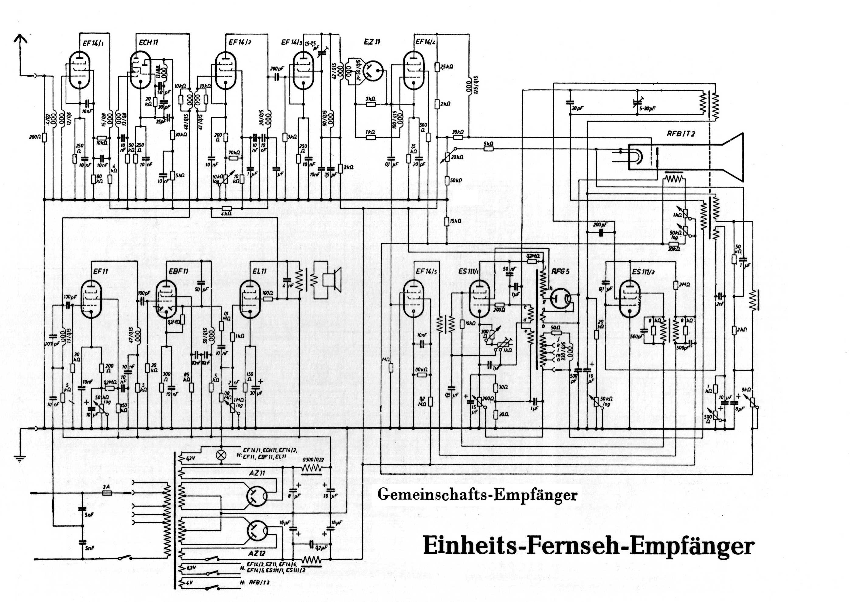
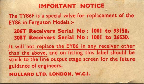
.png)
General literature and data sheets
- Mirrors in Brazil • Brazil searchable • Germany • Germany • Hong Kong • Hong Kong • Hungary • Poland[fast] • Poland searchable • Romania • Romania searchable • Sweden • USA • USA
- Tubebooks.org datasheet collection
- Roy J. Tellason's tube datasheet collection
- Klausmobile Russian tube directory
- General Electric Essential Characteristics, 1970
- RCA Receiving Tube Manuals R10 (1932) • RC11 (1933) • RC12 (1934) • RC13 (1937) • RC14 (1942) • RC15 (1948) • RC16 (1951) • RC17 (1954) • RC18 (1956) • RC19 (1959) • RC20 (1960) • RC21 (1961) • RC22 (1963) • RC23 (1964) • RC24 (1965) • RC25 (1966) • RC26 (1968) • RC27 (1970) • RC28 (1971) • RC29 (1973) • RC30 (1975)
- Scanned tube documentation (PDFs): Tubebooks • Frank Philipse • 4tubes
- Sylvania Technical Manual, 1958
- J. P. Hawker (ed), Radio and television servicing, Newnes, London, 1964
- Camera tube datasheets
- • Decoding type numbers
- Decoding Valve, Transistor and CRT Numbers
- Vacuum Tube Numbering Schemes, Bases & Bulbs
- European tube designation systems: • •
External links
| Wikimedia Commons has media related to |
- Vacuum Tube Data Sheet Locator
- Tube Substitution and Characteristics Guide
- British virtual thermionic valve museum with good quality pictures and data
- Belgian virtual thermionic valve museum with good quality pictures and data
- Radio museum
- Virtual Valve Museum