Lightbulb socket
A lightbulb socket, light socket, lamp socket or lampholder is a device which mechanically supports and provides electrical connections for a compatible electric lamp. Sockets allow lamps to be safely and conveniently replaced (re-lamping). There are many different standards for lampholders, including early de facto standards and later standards created by various standards bodies. Many of the later standards conform to a general coding system in which a socket type is designated by a letter or abbreviation followed by a number.[1]
The most common type of sockets for mains electricity are Edison screws, used in continental Europe and North America, while bayonet mounts dominate in the Commonwealth countries and in the automotive industry. Fluorescent lamps typically require a two-pin, unthreaded socket.
Not all lamps require a socket. For example, some miniature lamps have wire leads suitable for direct connection to screw terminals or other wires, and some reflector lamps provide screw terminals for electrical connections.
History
Early experimental incandescent lamps employed wire leads which had to be connected to screw terminals, but this was inconvenient for commercial use. The Edison organization used simple wooden receptacles with internal copper strips for lamps on the commercial steamship SS Columbia, the first ship to use electric light bulbs. These sockets included key switches, but required bulbs to be mounted upright.
The Edison organization developed a screw-base in 1880 which was initially made of wood but later made of plaster of Paris.[2] Many competitive designs of lamps and sockets appeared in the early era of incandescent lighting, which often were incompatible with other designs.
Construction and materials
The construction of a lampholder socket defines and limits its intended use. Ceramic insulation can withstand considerably higher operating temperatures than bakelite or other plastics. The electrical components and wires must be designed to carry the intended current plus a safety factor.
The contact surface area, thickness and conductivity of the metal, connection methods and maximum operating temperature must all be considered in the design of a new socket. In addition, mechanical factors such as shape of the socket, fixture mounting and attachment, lamp support, ease of re-lamping and total cost of manufacture must be considered. Sockets designed for ordinary household and industrial use have much more design leeway than those used in precision applications.
The lampholder must be located far enough from the filament that the metals with the lowest melting point will remain solid. Historically this metal was a tin/lead solder whose melting point might be as low as 180 °C (360 °F). Due to the thermal changes from ambient temperature to full operating temperature, the design of a socket must allow for a considerable amount of expansion and contraction. Spring elements are required to accommodate these dimensional changes. However, the temperature at which a metal loses its spring is far below the melting point. This is why some older sockets that no longer work can be restored by prying up the base spring slightly.
Lampholder failures are usually caused by mechanical abuse or by overheating. A socket with a built-in switch is far more likely to fail in normal use as the switch parts wear out. Insulation failures are usually caused by impacts or by difficulty inserting or removing a lamp. Sockets used outdoors or in damp areas often suffer from corrosion which can cause the lamp to "stick" in the socket and attempts to change a lamp can result in breakage of either the lamp or the lampholder. The corrosion is not only environmentally produced but may be a result of the current flowing through the parts when there is appreciable resistance between the parts. Fixtures in such environments may require gaskets or other waterproofing methods to prevent buildup of moisture in the socket area.
Edison screw bases

- E10 Miniature (Flashlight lamp)
- E11 Mini-Candelabra
- E12 Candelabra
- E14 European
- E17 Intermediate
- E26 Medium
- E27 Medium
- E39 Mogul
- E40 Mogul
- 3-Way (modified medium or mogul socket with additional ring contact for 3-way lamps)
- Skirted (PAR-38)
The light bulb commonly used since the early 20th century for general-purpose lighting applications, with a pear-like shape and an Edison screw base, is referred to as an "A-series light bulb." This most common general purpose bulb type would be classed as "A19/E26" or the metric version "A60/E27".
Bayonet styles

- BA9s Miniature bayonet
- BA15s Single Contact Bayonet
- BA15d Double Contact Bayonet
- Bay15d Indexed DC Bayonet
- Bay22 Double Contact Bayonet
- Bayonet Candelabra with prefocusing collar
- P28s Medium prefocus
- P40s Mogul prefocus
Bi-post
With bi-post bases, lamp orientation is fixed so filament will always be in the focal plane. Filament configurations such as the C13D (coiled, zig-zagged) emit far more light perpendicular to the zig-zag than parallel to it.
- Mogul bi-post (G38) can handle up to 100 amps and is used with searchlights and film & stage lighting fixtures of 1000 watts or larger. Incandescent, halogen and HMI light sources use this design.
- Medium bi-post (G22) is used with film & stage lighting fixtures between 250 and 1000 watts.
- Mini bi-post (G4-G6)
Common types:
- G4 - 4 mm pin spacing
- GU4 & GZ4 - are same as G4 and only denote what lamp mount clip is needed to hold the actual light bulb in place
- G5.3 - 5.3 mm pin spacing
- GU5.3, GX5.3, GY5.3, GZ5.3 - are same as G5.3 and only denote what lamp mount clip is needed to hold the actual light bulb in place
- G6.35 - 6.35 mm spacing
- GY6.35 & GZ6.35 - are same as G6.35 and only denote what lamp mount clip is needed to hold the actual light bulb in place
- G8 - 8 mm pin spacing
- GU8 - same as G8 and only denotes what lamp mount clip is needed to hold the actual light bulb in place
- GY8.6 - 8.6 mm pin spacing
- G9 - 9 mm pin spacing
- G12 - 12 mm pin spacing
Bi-pin connector
- Medium bi-pin is used on each end of a T12 fluorescent lamp
- Mini bi-pin is used with MR16 halogen lamps
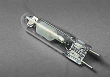
The two-pin socket is an update of the bi-post design with smaller pins designed to reduce the cost of manufacture. The 1000-watt FEL medium two-pin base halogen lamp allows designers to insert the lamp into the end of the ellipsoidal reflector through a smaller hole than previously possible with conventional incandescent lamps. This improves efficiency compared to the older side-inserted lamp or a double-ended lamp which requires two holes. One variation is the polarized two-pin socket – used primarily in projectors, which defines the exact positioning of the filament on one side. This improves the "point source" characteristic necessary for building complex optical systems.
Another facet of the two-pin design is that many new designs of lamps use baseless glass envelopes. The wire leads are thickened and crimped in the glass envelope of the lamp base. The MR16 is an example of this design; the actual lamp is inserted into the reflector with the leads sticking out and a ceramic paste used to glue it in.
Wedge base
Miniature lamps may have a wedge base made of glass or plastic. The base may be an extension of the glass envelope of the bulb, with the wire leads of the lamp folded up at the base. Some wedge bases are made of plastic and slipped over the wire leads. A wedge base holds the lamp by spring compression in the socket. The lamp is inserted and removed without twisting. Wedge base lamps are widely used in automotive applications, and many Christmas lights strings use plastic wedge-based bulbs.
Fluorescent tubular lamp standards
Fluorescent Linear Tube Light bulbs are measured in ⅛s of inches. So a T12 fluorescent is 12 ⅛s of an inch in diameter or 12/8 = 1.50"
- T4 - 4/8 or 0.500" in diameter
- T5 - 5/8 or 0.625" in diameter
- T8 - 8/8 or 1.00" in diameter
- T10 - 10/8 or 1.25" in diameter
- T12 - 12/8 or 1.50" in diameter
Lamp base styles
| Abbreviation | Term |
|---|---|
| Cand | Candelabra |
| DCB | Double contact bayonet candelabra |
| DC Pf | Double contact prefocus candelabra |
| EMEP | Extended mogul end prong ferrule contact |
| F | Ferrule contact |
| Mc | Minican |
| Med | Medium |
| Med Bp | Medium bipost |
| Med Pf | Medium Prefocus |
| Med Skt | Medium Skirted |
| Med 2P | Medium two pin |
| MEP | Mogul End Prong |
| Mog | Mogul |
| Mog Bp | Mogul bipost |
| Mog Pf | Mogul prefocus |
| MS | Miniature screw (with reference shoulder) |
| MSP | Medium side prong |
| G38 Bp | G38 mogul bipost |
| R7S | Also known as a double ended halogen lamp. Mainly used with linear halogen lamps measuring 118mm or 78mm. |
| Rect RSC | Rectangular recessed single contact |
| RM2P | Rim mount two pin |
| RSC | Recessed single contact |
| S | Metal sleeve |
| SC Bay | Single contact bayonet |
| SC Pf | Single contact prefocus |
| SFc 10-4 | Sleeve with threaded pin |
| SFc 15, 5-6 | Sleeve with threaded pin |
| ST | Screw terminal |
| TB2P | TruBeam two pin |
| Tf | Trufocus (also four pin) |
| TLMS | Tru-Loc miniature screw |
| 2B | Two button |
| 2PAG | Two pin all glass |
| 2PAGC | Two pin all glass with ceramic cover |
| 2PM | Two pin miniature |
| 2PP | Two pin prefocus |
| 3P | Three prong |
Some of the above base styles are now obsolete. The trend in recent years has been to design newer bases to reduce waste of raw materials and simplify the replacement process.
Standards
The United States standard for lamp sockets is published by ANSI and developed by NEMA. It is standard number C81.64, titled Guidelines and General Information for Electric Lamp Bases, Lampholders, and Gauges and outlines the dimensions and tolerances of standardized lamp sockets. Lamp bases are standardized in C81.61 Standard for Electrical Lamp Bases - Specifications for Bases (Caps) for Electric Lamps.[3] Both standards are harmonized with IEC standard 600061 and include dimensional data sheets as printed in the IEC standard.
References
- ↑ "The Advantages of Using LED Verlichting". The Difference of Connections. LED Spots & LED Inbouwspots. Archived from the original on 16 August 2013. Retrieved 16 August 2013.
- ↑ Robert Friedel, Paul Israel, Edison's Electric Light: Biography of an Invention, Rutgers University Press, 1986, ISBN 0-8135-1118-6, pp. 169-171
- ↑ ANSI Std. C81.61-2009
External links
| Wikimedia Commons has media related to Lampholder sockets. |
- Early Electrical Lighting in Homes illustrations of historic light sockets and outlets