Electrical ballast
An electrical ballast is a device placed in line with the load to limit the amount of current in an electrical circuit. It may be a fixed or variable resistor.
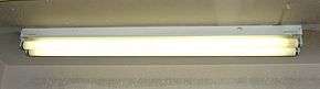
A familiar and widely used example is the inductive ballast used in fluorescent lamps to limit the current through the tube, which would otherwise rise to a destructive level due to the negative differential resistance of the tube's voltage-current characteristic.
Ballasts vary greatly in complexity. They may be as simple as a resistor, inductor or capacitor (or a combination of these) wired in series with the lamp; or as complex as the electronic ballasts used in compact fluorescent lamps and high-intensity discharge lamps.
Current limiting

An electrical ballast is a device which limits the current through an electrical load. These are most often used when a load (such as an arc discharge) has its terminal voltage decline when current through the load increases. If such a device were connected to a constant-voltage power supply, it would draw an increasing amount of current until it will be destroyed or caused the power supply to fail. To prevent this, a ballast provides a positive resistance or reactance that limits the current. The ballast provides for the proper operation of the negative-resistance device by limiting current.
Ballasts can also be used simply to limit the current in an ordinary, positive-resistance circuit. Prior to the advent of solid-state ignition, automobile ignition systems commonly included a ballast resistor to regulate the voltage applied to the ignition system.
Series resistors are used as ballasts to control the current through LEDs.
Resistors
Fixed resistors
For simple, low-powered loads such as a neon lamp or a LED, a fixed resistor is commonly used. Because the resistance of the ballast resistor is large it determines the current in the circuit, even in the face of negative resistance introduced by the neon lamp.
Ballast was also a component used in early model automobiles engine that lowered the supply voltage to the ignition system after the engine had been started. Starting the engine requires a significant amount of electrical current from the battery, resulting in an equally significant voltage drop. To allow the engine to start, the ignition system was designed to operate on this lower voltage. But once the vehicle was started and the starter disengaged, the normal operating voltage was too high for the ignition system. To avoid this problem, a ballast resistor was inserted in series with the ignition system, resulting in two different operating voltages for the starting and ignition systems.
Occasionally, this ballast resistor would fail and the classic symptom of this failure was that the engine ran while being cranked (while the resistor was bypassed) but stalled immediately when cranking ceased (and the resistor was reconnected in the circuit via the ignition switch). Modern electronic ignition systems (those used since the 1980s or late '70s) do not require a ballast resistor as they are flexible enough to operate on the lower cranking voltage or the normal operating voltage.
Another common use of a ballast resistor in the automotive industry is adjusting the ventilation fan speed. The ballast is a fixed resistor with usually two center taps, and the fan speed selector switch is used to bypass portions of the ballast: all of them for full speed, and none for the low speed setting. A very common failure occurs when the fan is being constantly run at the next-to-full speed setting (usually 3 out of 4). This will cause a very short piece of resistor coil to be operated with a relatively high current (up to 10 A), eventually burning it out. This will render the fan unable to run at the reduced speed settings.
In some consumer electronic equipment, notably in television sets in the era of valves (vacuum tubes), but also in some low-cost record players, the vacuum tube heaters were connected in series. Since the voltage drop across all the heaters in series was usually less than the full mains voltage, it was necessary to provide a ballast to drop the excess voltage. A resistor was often used for this purpose, as it was cheap and worked with both AC and DC.
Self-variable resistors
Some ballast resistors have the property of increasing in resistance as current through them increases, and decreasing in resistance as current decreases. Physically, some such devices are often built quite like incandescent lamps. Like the tungsten filament of an ordinary incandescent lamp, if current increases, the ballast resistor gets hotter, its resistance goes up, and its voltage drop increases. If current decreases, the ballast resistor gets colder, its resistance drops, and the voltage drop decreases. Therefore, the ballast resistor reduces variations in current, despite variations in applied voltage or changes in the rest of an electric circuit. These devices are sometimes called "barretters" and were used in the series heating circuits of 1930s to 1960s AC/DC radio and TV home receivers.
This property can lead to more precise current control than merely choosing an appropriate fixed resistor. The power lost in the resistive ballast is also reduced because a smaller portion of the overall power is dropped in the ballast compared to what might be required with a fixed resistor.
Earlier, household clothes dryers sometimes incorporated a germicidal lamp in series with an ordinary incandescent lamp; the incandescent lamp operated as the ballast for the germicidal lamp. A commonly used light in the home in the 1960s in 220–240 V countries was a circular tube ballasted by an under-run regular mains filament lamp. Self ballasted mercury-vapor lamps incorporate ordinary tungsten filaments within the overall envelope of the lamp to act as the ballast, and it supplements the otherwise lacking red area of the light spectrum produced.
Reactive ballasts
Because of the power that would be lost, resistors are not used as ballasts for lamps of more than about two watts. Instead, a reactance is used. Losses in the ballast due to its resistance and losses in its magnetic core may be significant, on the order of 5 to 25% of the lamp input electric power. Practical lighting design calculations must allow for ballast loss in estimating the running cost of a lighting installation.
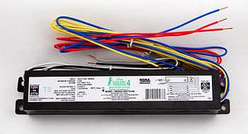
An inductor is very common in line-frequency ballasts to provide the proper starting and operating electrical condition to power a fluorescent lamp, neon lamp, or high intensity discharge (HID) lamp. (Because of the use of the inductor, such ballasts are usually called magnetic ballasts.) The inductor has two benefits:
- Its reactance limits the power available to the lamp with only minimal power losses in the inductor
- The voltage spike produced when current through the inductor is rapidly interrupted is used in some circuits to first strike the arc in the lamp.
A disadvantage of the inductor is that current is shifted out of phase with the voltage, producing a poor power factor. In more expensive ballasts, a capacitor is often paired with the inductor to correct the power factor. In ballasts that control two or more lamps, line-frequency ballasts commonly use different phase relationships between the multiple lamps. This not only mitigates the flicker of the individual lamps, it also helps maintain a high power factor. These ballasts are often called lead-lag ballasts because the current in one lamp leads the mains phase and the current in the other lamp lags the mains phase.
In Europe, and most 220-240 V territories, the line voltage is sufficient to start lamps over 20W with a series inductor. In North America and Japan however, the line voltage (120 V or 100 V respectively) may not be sufficient to start lamps over 20 W with a series inductor, so an autotransformer winding is included in the ballast to step up the voltage. The autotransformer is designed with enough leakage inductance (short-circuit inductance) so that the current is appropriately limited.
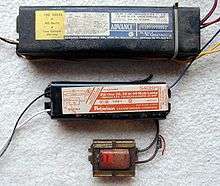
Because of the large inductors and capacitors that must be used, reactive ballasts operated at line frequency tend to be large and heavy. They commonly also produce acoustic noise (line-frequency hum).
Prior to 1980 in the United States, PCB-based oils were used as an insulating oil in many ballasts to provide cooling and electrical isolation (see transformer oil).
Electronic and magnetic ballasts
An electronic ballast uses solid state electronic circuitry to provide the proper starting and operating electrical conditions to power discharge lamps. An electronic ballast can be smaller and lighter than a comparably-rated magnetic one. An electronic ballast is usually quieter than a magnetic one, which produces a line-frequency hum by vibration of the transformer laminations.[4]
Electronic ballasts are often based on SMPS topology, first rectifying the input power and then chopping it at a high frequency. Advanced electronic ballasts may allow dimming via pulse-width modulation or via changing the frequency to a higher value. Ballasts incorporating a microcontroller (digital ballasts) may offer remote control and monitoring via networks such as LonWorks, DALI, DMX512, DSI or simple analog control using a 0-10 V DC brightness control signal. Systems with remote control of light level via a wireless mesh network have been introduced.[5]

Electronic ballasts usually supply power to the lamp at a frequency of 20,000 Hz or higher, rather than the mains frequency of 50 – 60 Hz; this substantially eliminates the stroboscopic effect of flicker, a product of the line frequency associated with fluorescent lighting (see photosensitive epilepsy). The high output frequency of an electronic ballast refreshes the phosphors in a fluorescent lamp so rapidly that there is no perceptible flicker. The flicker index, used for measuring perceptible light modulation, has a range from 0.00 to 1.00, with 0 indicating the lowest possibility of flickering and 1 indicating the highest. Lamps operated on magnetic ballasts have a flicker index between 0.04–0.07 while digital ballasts have a flicker index of below 0.01.[6]
Because more gas remains ionized in the arc stream, the lamp operates at about 9% higher efficacy above approximately 10 kHz. Lamp efficiency increases sharply at about 10 kHz and continues to improve until approximately 20 kHz.[7] Electronic ballast retrofits to existing street lights had been tested in some Canadian provinces circa 2012[8]; since then LED retrofits have become more common.
With the higher efficiency of the ballast itself and the higher lamp efficacy at higher frequency, electronic ballasts offer higher system efficacy for low pressure lamps like the fluorescent lamp. For HID lamps, there is no improvement of the lamp efficacy in using higher frequency, but for these lamps the ballast losses are lower at higher frequencies and also the light depreciation is lower, meaning the lamp produces more light over its entire lifespan. Some HID lamp types like the ceramic discharge metal halide lamp have reduced reliability when operated at high frequencies in the range of 20 – 200 kHz; for these lamps a square wave low frequency current drive is mostly used with frequency in the range of 100 – 400 Hz, with the same advantage of lower light depreciation.
Application of electronic ballasts to HID lighting is growing in popularity. Most newer generation electronic ballasts can operate both high pressure sodium (HPS) lamps as well as metal-halide lamps, reducing costs for building managers who use both types of lamps. The ballast initially works as a starter for the arc, supplying a high-voltage impulse and, later, it works as a limiter/regulator of the electric flow inside the circuit. Electronic ballasts also run much cooler and are lighter than their magnetic counterparts.[6]
Fluorescent lamp ballasts
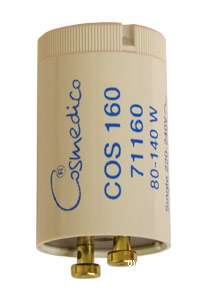
Preheating
This technique uses a combination filament–cathode at each end of the lamp in conjunction with a mechanical or automatic (bi-metallic or electronic) switch that initially connect the filaments in series with the ballast to preheat them. When filaments are disconnected, an inductive pulse from the ballast starts the lamp. This system is described as "Preheat" in North America and "Switch Start" in the UK, and have no specific name in the rest part of the world. This systems is common in 200–240 V countries (and for 100–120 V lamps up to about 30 watts).
Although an inductive pulse makes it more likely that the lamp will start when the starter switch opens, it is not actually necessary. The ballast in such systems can equally be a resistor. A number of fluorescent lamp fittings used a filament lamp as the ballast in the late 1950s through to the 1960s. Special lamps were manufactured that were rated at 170 volts and 120 watts. The lamp had a thermal starter built into the 4 pin base. The power requirements were much larger than using an inductive ballast (though the consumed current was the same), but the warmer light from the lamp type of ballast was often preferred by users particularly in a domestic environment.
Resistive ballasts were the only type that was usable when the only supply available to power the fluorescent lamp was DC. Such fittings used the thermal type of starter (mostly because they had gone out use long before the glow starter was invented), but it was possible to include a choke in the circuit whose sole purpose was to provide a pulse on opening of the starter switch to improve starting. DC fittings were complicated by the need to reverse the polarity of the supply to the tube each time it started. Failure to do so vastly shortened the life of the tube.
Instant start
An instant start ballast does not preheat the electrodes, instead using a relatively high voltage (~600 V) to initiate the discharge arc. It is the most energy efficient type, but yields the fewest lamp-start cycles, as material is blasted from the surface of the cold electrodes each time the lamp is turned on. Instant-start ballasts are best suited to applications with long duty cycles, where the lamps are not frequently turned on and off. Although these were mostly used in countries with 100-120 volt mains supplies (for lamps of 40 W or above), they were briefly popular in other countries because the lamp started without the flicker of switch start systems. The popularity was short lived because of the short lamp life.
Rapid start
A rapid start ballast applies voltage and heats the cathodes simultaneously. It provides superior lamp life and more cycle life, but uses slightly more energy as the electrodes in each end of the lamp continue to consume heating power as the lamp operates. Again, although popular in 100-120 volt countries for lamps of 40 W and above, rapid start is sometimes used in other countries particularly where the flicker of switch start systems is undesirable.
Dimmable ballast
A dimmable ballast is very similar to a rapid start ballast, but usually has a capacitor incorporated to give a power factor nearer to unity than a standard rapid start ballast. A quadrac type light dimmer can be used with a dimming ballast, which maintains the heating current while allowing lamp current to be controlled. A resistor of about 10 kΩ is required to be connected in parallel with the fluorescent tube to allow reliable firing of the quadrac at low light levels.
Programmed start
Used in high end electronic fluorescent ballasts. This ballast applies power to the filaments first, it allows the cathodes to preheat and then applies voltage to the lamps to strike an arc. Lamp life typically operates up to 100,000 on/off cycles when using programmed start ballasts. Once started, filament voltage is reduced to increase operating efficiency.[9] This ballast gives the best life and most starts from lamps, and so is preferred for applications with very frequent power cycling such as vision examination rooms and restrooms with a motion detector switch.
Hybrid
A hybrid ballast has a magnetic core-and-coil transformer and an electronic switch for the electrode-heating circuit. Like a magnetic ballast, a hybrid unit operates at line power frequency—50 Hz in Europe, for example. These types of ballasts, which are also referred to as cathode-disconnect ballasts, disconnect the electrode-heating circuit after they start the lamps.
ANSI Ballast factor
For a lighting ballast, the ANSI ballast factor is used in North America to compare the light output (in lumens) of a lamp operated on a ballast compared to the lamp operating on an ANSI reference ballast. Reference ballast operates the lamp at its ANSI specified nominal power rating.[10][11] The ballast factor of practical ballasts must be considered in lighting design; a low ballast factor may save energy, but will produce less light. With fluorescent lamps, ballast factor can vary from the reference value of 1.0.[12]
Ballast triode
Early tube-based color TV sets used a ballast triode, such as the PD500, as a parallel shunt stabilizer for the CRT acceleration voltage, to keep the CRT's deflection factor constant.
See also
References
- 1 2 3 Sinclair, Ian Robertson (2001). Sensors and transducers, 3rd Ed. Newnes. pp. 69–70. ISBN 0750649321.
- ↑ Kularatna, Nihal (1998). Power Electronics Design Handbook. Newnes. pp. 232–233. ISBN 0750670738.
- ↑ Aluf, Ofer (2012). Optoisolation Circuits: Nonlinearity Applications in Engineering. World Scientific. pp. 8–11. ISBN 9814317004. This source uses the term "absolute negative differential resistance" to refer to active resistance
- ↑ "Understanding Transformer Noise" (PDF). federalpacific.com. Federal Pacific. Retrieved 8 August 2015.
- ↑ "infiNET dimmer datasheet" (PDF). Crestron Electronics, Inc. 9 March 2005. Retrieved 22 July 2013.
- 1 2 Specifier Reports: Electronic Ballasts p.18, National Lighting Product Information Program, Volume 8 Number 1, May 2000. Retrieved 13 May 2013.
- ↑ IES Lighting Handbook 1984
- ↑ "Archived copy". Archived from the original on 2013-07-29. Retrieved 2012-06-23.
- ↑ "What Are Fluorescent Ballast Starting Methods?". Bulbsdepot.com. 2014-02-14. Retrieved 2014-03-11.
- ↑ IEEE Std. 100 "Dictionary of IEEE Standards Terms, Standard 100" , ISBN 0-7381-2601-2, page 83
- ↑ ANSI standard C82.13-2002 Definitions for Flurorescent Lamp Ballasts", page 1
- ↑ "Ballast factor". Lawrence Berkeley National Laboratory. Archived from the original on March 19, 2013. Retrieved April 12, 2013.
External links
| Wikimedia Commons has media related to Electrical ballasts. |
| Wikimedia Commons has media related to Starters. |
| Wikimedia Commons has media related to Fluorescent lamp power supplies (includes electronic ballasts). |