Valve RF amplifier
A valve RF amplifier (UK and Aus.) or tube amplifier (U.S.), is a device for electrically amplifying the power of an electrical radio frequency signal.
Low to medium power valve amplifiers for frequencies below the microwaves were largely replaced by solid state amplifiers during the 1960s and 1970s, initially for receivers and low power stages of transmitters, transmitter output stages switching to transistors somewhat later. Specially constructed valves are still in use for very high power transmitters, although rarely in new designs.
Valve characteristics
Valves are high voltage/low current devices in comparison with transistors. Tetrode and pentode valves have very flat anode current vs. anode voltage indicating high anode output impedances. Triodes show a stronger relationship between anode voltage and anode current.
The high working voltage makes them well suited for radio transmitters and valves remain in use today for very high power short wave radio transmitters, where solid state techniques would require many devices in parallel, and very high DC supply currents. High power solid state transmitters also require complex combining and tuning networks, whereas a valve-based transmitter would use a single relatively simple tuned network. Thus while solid state high power short wave transmitters are technically possible, economic considerations still favor valves above 3 MHz and 10,000 watts. Amateurs also use valve amplifiers in the 500-1500 watt range mainly for economic reasons.
Audio vs. RF amplifiers
Valve audio amplifiers typically amplify the entire audio range between 20 Hz and 20 kHz or higher. They use an iron core transformer to provide a suitable high impedance load to the valve(s) while driving a speaker, which is typically 8 Ohms. Audio amplifiers normally use a single valve in class A, or a pair in class B or class AB.
An RF power amplifier is tuned to a single frequency as low as 18 kHz and as high as the UHF range of frequencies, for the purpose of radio transmission or industrial heating. They use a narrow tuned circuit to provide the valve with a suitably high load impedance and feed a load that is typically 50 or 75 Ohms. RF amplifiers normally operate Class C or Class AB.
Although the frequency ranges for audio amplifiers and RF amplifiers overlap, the class of operation, method of output coupling and percent operational bandwidth will differ. Power valves are capable of high frequency response, up to at least 30 MHz. Indeed, many of the Directly Heated Single Ended Triode (DH-SET) audio amplifiers use radio transmitting valves originally designed to operate as RF amplifiers in the high frequency range.
Circuit advantages of valves
- Very linear (especially triodes) making it viable to use them in low distortion linear circuits with little or no negative feedback
- High input impedance, comparable to that of FETs, higher than in bipolar transistors, which is beneficial in certain signal amplification applications.
- Valves are high voltage devices, inherently suitable for higher voltage circuits than most semiconductors.
- Valves can be constructed on a scale that can dissipate large amounts of heat, with very high power models designed for water or vapor cooling. For this reason valves remained the only viable technology for very high power, and especially high power/high voltage applications such as Radio & TV transmitters long into the age when transistors had displaced valves in most other applications. However today these also are increasingly obsolete.
- Lower investment cost in applications like RF amplifiers above the kilowatt power range[1] Also, large, high value power valves can to some extent be remanufactured to extend residual life.
- Electrically very robust, they can tolerate overloads which would destroy bipolar transistor systems in milliseconds (of particular significance in military and other "strategically important" systems).
- Indefinite shelf life. Even 60-year-old tubes can be perfectly functional, and many types are available for purchase as "new-old-stock". Thus, despite known reliability issues (see below), it is still perfectly possible to run most very old vacuum tube equipment.
- Comparative ease of replacement. Being known to be subject to a number of common failure modes, most tubes were designed and installed as plug-in devices, not soldered into a circuit. A failed tube can simply be unplugged and replaced by a user, while the failure of a soldered-in semiconductor may imply damage beyond economic repair for a whole product or subassembly.
Disadvantages of valves
- Cost. For most applications, tubes require both greater initial outlay and running expense per amplification stage, requiring more attentive budgeting of the number of stages for a given application compared to semiconductors.
- Short operational life. In the most common applications, valves have a working life of just a few thousand hours, much shorter than solid state parts. This is due various commonplace failure mechanisms: cathode depletion, open or shorts circuits—notably of the heater and grid structures, cathode poisoning, and physical breakage of the glass envelope. Heater failure most often happens due to the mechanical stress of a cold start. Only, in certain always-on professional applications such as specialized computing and undersea cables, specially designed valves in carefully designed circuits and well cooled environments reached operational lives of tens or hundreds of thousands of hours.
- Heater supplies are required for the cathodes. Beside the investment cost, the share of the power budget that goes into heating the cathode without contributing to output can range from few percent points of anode dissipation (in high power applications at full output),[2] to broadly comparable to anode dissipation in small signal applications.[3]
- Large circuit temperature swings in on/off cycles. Massive stray heat from cathode heaters in common low power tubes means that adjoining circuits experience changes in temperature that can exceed 100 °C / 200 °F. This requires heat resistant components. In RF applications this also means that all frequency-determining components may have to heat to thermal equilibrium before frequency stability is reached. While at AM broadcast (medium wave) receivers and in loosely tuned TV sets this was not a problem, in typical radio receivers and transmitters with free-running oscillators at HF frequencies this thermal stabilization required about one hour. On the other hand, miniature ultra-low power direct-heated valves do not produce much heat in absolute terms, cause more modest temperature swings, and allow equipment that contains few of them to stabilize sooner.[4][5]
- No "instant on" from a cold start. Valve cathodes need to heat to a glow to start conducting. In indirect-heating cathodes this could take up to 20 seconds. Apart from temperature-related instability, this meant that valves would not work instantly when powered. This led to development of always-on preheating systems for vacuum tube appliances that shortened the wait and may have reduced valve failures from thermal shock, but at the price of a continuous power drain, and an increased fire hazard. On the other hand, very small, ultra low power direct-heated valves turn on in tenths of a second from a cold start.
- Anodes may require dangerously high voltages.
- High impedance / low current output unsuitable for direct drive of many real world loads, notably various forms of electric motor
- Compared to transistors, valves have the disadvantage of being available in a single polarity only. In most processes transistors are available in complementary polarities (e.g., NPN/PNP), making possible many circuit configurations that cannot be realized with valves.
Distortion
The most efficient valve-based RF amplifiers operate Class C. If used with no tuned circuit in the output, this would distort the input signal, producing harmonics. However, class C amplifiers normally use a high Q output network which removes the harmonics, leaving an undistorted sine wave identical to the input waveform. Class C is suitable only for amplifying signals with a constant amplitude, such as FM, FSK, and some CW (Morse code) signals. Where the amplitude of the input signal to the amplifier varies as with single sideband modulation, amplitude modulation, video and complex digital signals, the amplifier must operate class A or AB, to preserve the envelope of the driving signal in an undistorted form. Such amplifiers are referred to as linear amplifiers.
It is also common to modify the gain of an amplifier operating class C so as to produce amplitude modulation. If done in a linear manner, this modulated amplifier is capable of low distortion. The output signal can be viewed as a product of the input RF signal and the modulating signal.
The development of FM broadcasting improved fidelity by using a greater bandwidth which was available in the VHF range, and where atmospheric noise was absent. FM also has an inherent ability to reject noise, which is mostly amplitude modulated. Valve technology suffers high-frequency limitations due to cathode-anode transit time. However, tetrodes are successfully used into the VHF range and triodes into the low GHz range. Modern FM broadcast transmitters use both valve and solid state devices, with valves tending to be more used at the highest power levels. FM transmitters operate class C with very low distortion.
Today’s “digital” radio that carries coded data over various phase modulations (such as GMSK, QPSK etc.) and also the increasing demand for spectrum have forced a dramatic change in the way radio is used, e.g. the cellular radio concept. Today’s cellular radio and digital broadcast standards are extremely demanding in terms of the spectral envelope and out of band emissions that are acceptable (in the case of GSM for example, −70 dB or better just a few hundred kilohertz from center frequency). Digital transmitters must therefore operate in the linear modes, with much attention given to achieving low distortion.
Applications
Historic transmitters and receivers
(High voltage / High power) Valve stages were used to amplify the received radio frequency signals, the intermediate frequencies, the video signal and the audio signals at the various points in the receiver. Historically (pre WWII) "transmitting tubes" were among the most powerful tubes available, were usually direct heated by thoriated filaments that glowed like light bulbs. Some tubes were built to be very rugged, capable of being driven so hard that the anode would itself glow cherry red, the anodes being machined from solid material (rather than fabricated from thin sheet) to be able to withstand this without distorting when heated. Notable tubes of this type are the 845 and 211. Later beam power tubes such as the 807 and (direct heated) 813 were also used in large numbers in (especially military) radio transmitters.
Bandwidth of valve vs solid state amplifiers
Today, radio transmitters are overwhelmingly solid state, even at microwave frequencies (cellular radio base stations). Depending on the application, a fair number of radio frequency amplifiers continue to have valve construction, due to their simplicity, where as, it takes several output transistors with complex splitting and combining circuits to equal the same amount of output power of a single valve.
Valve amplifier circuits are significantly different from broadband solid state circuits. Solid state devices have a very low output impedance which allows matching via a broadband transformer covering a large range of frequencies, for example 1.8 to 30 MHz. With either class C or AB operation, these must include low pass filters to remove harmonics. While the proper low pass filter must be switch selected for the frequency range of interest, the result is considered to be a "no tune" design. Valve amplifiers have a tuned network that serves as both the low pass harmonic filter and impedance matching to the output load. In either case, both solid state and valve devices need such filtering networks before the RF signal is output to the load.
Radio circuits
Unlike audio amplifiers, in which the analog output signal is of the same form and frequency as the input signal, RF circuits may modulate low frequency information (audio, video, or data) onto a carrier (at a much higher frequency), and the circuitry comprises several distinct stages. For example, a radio transmitter may contain:
- an audio frequency (AF) stage (typically using conventional broadband small signal circuitry as described in Valve audio amplifier,
- one or more oscillator stages that generate the carrier wave,
- one or more mixer stages that modulate the carrier signal from the oscillator,
- the amplifier stage itself operating at (typically) high frequency. the Transmitter power amp itself is the only high power stage in a radio system, and operates at the carrier frequency. In AM, the modulation (frequency mixing) usually takes place in the final amplifier itself.
Transmitter anode circuits
The most common anode circuit is a tuned LC circuit where the anodes are connected at a voltage node. This circuit is often known as the anode tank circuit.
Active (or tuned grid) amplifier
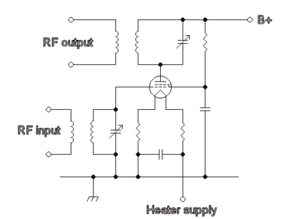
An example of this used at VHF/UHF include the 4CX250B, an example of a twin tetrode is the QQV06/40A.
Neutralization is a term used in TGTP (tuned grid tuned plate) amplifiers for the methods and circuits used for stabilization against unwanted oscillations at the operating frequency caused by the inadvertent introduction of some of the output signal back into the input circuits. This mainly occurs via the grid to plate capacity, but can also come via other paths, making circuit layout important. To cancel the unwanted feedback signal, a portion of the output signal is deliberately introduced into the input circuit with the same amplitude but opposite phase.
When using a tuned circuit in the input, the network must match the driving source to the input impedance of the grid. This impedance will be determined by the grid current in Class C or AB2 operation. In AB1 operation, the grid circuit should be designed to avoid excessive step up voltage, which although it might provide more stage gain, as in audio designs, it will increase instability and make neutralization more critical.
In common with all three basic designs shown here, the anode of the valve is connected to a resonant LC circuit which has another inductive link which allows the RF signal to be passed to the output. The circuit shown has been largely replaced by a Pi network which allows simpler adjustment and adds low pass filtering.
Operation
The anode current is controlled by the electrical potential (voltage) of the first grid. A DC bias is applied to the valve to ensure that the part of the transfer equation which is most suitable to the required application is used. The input signal is able to perturb (change) the potential of the grid, this in turn will change the anode current (also known as the plate current).
In the RF designs shown on this page, a tuned circuit is between the anode and the high voltage supply. This tuned circuit is brought to resonance presenting an inductive load that is well matched to the valve and thus results in an efficient power transfer.
As the current flowing through the anode connection is controlled by the grid, then the current flowing through the load is also controlled by the grid.
One of the disadvantages of a tuned grid compared to other RF designs is that neutralization is required.
Passive grid amplifier
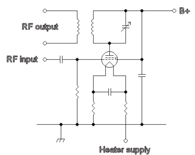
A passive grid circuit used at VHF/UHF frequencies might use the 4CX250B tetrode. An example of a twin tetrode would be the QQV06/40A. The tetrode has a screen grid which is between the anode and the first grid, which being grounded for RF, acts as a shield to reducing the effective capacitance between the first grid and the anode. The combination of the effects of the screen grid and the grid damping resistor often allow the use of this design without neutralization. The screen found in tetrodes and pentodes, greatly increases the valve's gain by reducing the effect of anode voltage on anode current.
The input signal is applied to the valve's first grid via a capacitor. The value of the grid resistor determines the gain of the amplifier stage. The higher the resistor the greater the gain, the lower the damping effect and the greater the risk of instability. With this type of stage good layout is less vital.
Advantages
- Stable, no neutralizing required normally
- Constant load on the exciting stage
Disadvantages
- Low gain, more input power is required
- Less gain than tuned grid
- Less filtering than tuned grid (more broadband), hence the amplification of out of band spurious signals, such as harmonics, from an exciter is greater
Grounded grid amplifier

This design normally uses a triode so valves such as the 4CX250B are not suitable for this circuit, unless the screen and control grids are joined, effectively converting the tetrode into a triode. This circuit design has been used at 1296 MHz using disk seal triode valves such as the 2C39A.
The grid is grounded and the drive is applied to the cathode through a capacitor. The heater supply must be isolated from the cathode as unlike the other designs the cathode is not connected to RF ground. Some valves, such as the 811A, are designed for "zero bias" operation and the cathode can be at ground potential for DC. Valves that require a negative grid bias can be used by putting a positive DC voltage on the cathode. This can be achieved by putting a zener diode between the cathode and ground or using a separate bias supply.
Advantages
- Stable, no neutralizing required normally
- Some of the power from exciting stage appears in the output
Disadvantages
- Relatively low gain, typically about 10 dB.
- The heater must be isolated from ground with chokes.
Neutralization
The valve interelectrode capacitance which exists between the input and output of the amplifier and other stray coupling may allow enough energy to feed back into input so as to cause self oscillation in an amplifier stage. For the higher gain designs this effect must be counteracted. Various methods exist for introducing an out of phase signal from the output back to the input so that the effect is cancelled. Even when the feed back is not sufficient to cause oscillation it can produce other effects, such as difficult tuning. Therefore, neutralization can be helpful, even for an amplifier that does not oscillate. Many grounded grid amplifiers use no neutralization, but at 30 MHz adding it can smooth out the tuning.
An important part of the neutralization of a tetrode or pentode is the design of the screen grid circuit. To provide the greatest shielding effect, the screen must be well grounded at the frequency of operation. Many valves will have a "self neutralizing" frequency somewhere in the VHF range. This results from a series resonance consisting of the screen capacity and the inductance of the screen lead thus providing a very low impedance path to ground.
UHF
Transit time effects are important at these frequencies, so feedback is not normally usable and for performance critical applications alternative linearisation techniques have to be used such as degeneration and feedforward.
Tube noise and noise figure
Noise figure is not usually an issue for power amplifier valves, however, in receivers using valves it can be important. While such uses are obsolete, this information is included for historical interest.
Like any amplifying device, valves add noise to the signal to be amplified. Even with a hypothetical perfect amplifier, however, noise is unavoidably present due to thermal fluctuations in the signal source (usually assumed to be at room temperature, T = 295 K). Such fluctuations cause an electrical noise power of , where kB is the Boltzmann constant and B the bandwidth. Correspondingly, the voltage noise of a resistance R into an open circuit is and the current noise into a short circuit is .


The noise figure is defined as the ratio of the noise power at the output of the amplifier relative to the noise power that would be present at the output if the amplifier were noiseless (due to amplification of thermal noise of the signal source). An equivalent definition is: noise figure is the factor by which insertion of the amplifier degrades the signal to noise ratio. It is often expressed in decibels (dB). An amplifier with a 0 dB noise figure would be perfect.
The noise properties of tubes at audio frequencies can be modeled well by a perfect noiseless tube having a source of voltage noise in series with the grid. For the EF86 tube, for example, this voltage noise is specified (see e.g., the Valvo, Telefunken or Philips data sheets) as 2 microvolts integrated over a frequency range of approximately 25 Hz to 10 kHz. (This refers to the integrated noise, see below for the frequency dependence of the noise spectral density.) This equals the voltage noise of a 25 kΩ resistor. Thus, if the signal source has an impedance of 25 kΩ or more, the noise of the tube is actually smaller than the noise of the source. For a source of 25 kΩ, the noise generated by tube and source are the same, so the total noise power at the output of the amplifier is twice the noise power at the output of the perfect amplifier. The noise figure is then two, or 3 dB. For higher impedances, such as 250 kΩ, the EF86's voltage noise is lower than the sources's own noise. It therefore adds 1/10 of the noise power caused by the source, and the noise figure is 0.4 dB. For a low-impedance source of 250 Ω, on the other hand, the noise voltage contribution of the tube is 10 times larger than the signal source, so that the noise power is one hundred times larger than that caused by the source. The noise figure in this case is 20 dB.

To obtain low noise figure the impedance of the source can be increased by a transformer. This is eventually limited by the input capacity of the tube, which sets a limit on how high the signal impedance can be made if a certain bandwidth is desired.
The noise voltage density of a given tube is a function of frequency. At frequencies above 10 kHz or so, it is basically constant ("white noise"). White noise is often expressed by an equivalent noise resistance, which is defined as the resistance which produces the same voltage noise as present at the tube input. For triodes, it is approximately (2-4)/gm, where gm is the transconductivity. For pentodes, it is higher, about (5-7)/gm. Tubes with high gm thus tend to have lower noise at high frequencies. For example, it is 300 Ω for one half of the ECC88, 250 Ω for an E188CC (both have gm = 12.5 mA/V) and as low as 65 Ω for a tride-connected D3a (gm = 40 mA/V).
In the audio frequency range (below 1–100 kHz), "1/f" noise becomes dominant, which rises like 1/f. (This is the reason for the relatively high noise resistamnce of the EF86 in the above example.) Thus, tubes with low noise at high frequency do not necessarily have low noise in the audio frequency range. For special low noise audio tubes, the frequency at which 1/f noise takes over is reduced as far as possible, maybe to something like a kilohertz. It can be reduced by choosing very pure materials for the cathode nickel, and running the tube at an optimized (generally low) anode current.
At radio frequencies, things are more complicated: (i) The input impedance of a tube has a real component that goes down like 1/f² (due to cathode lead inductance and transit time effects). This means the input impedance can no longer be increased arbitrarily in order to reduce the noise figure. (ii) This input resistance has its own thermal noise, just like any resistor. (The "temperature" of this resistor for noise purposes is more close to the cathode temperature than to room temperature). Thus, the noise figure of tube amplifiers increases with frequency. At 200 MHz, a noise figure of 2.5 (or 4 dB) can be reached with the ECC2000 tube in an optimized "cascode"-circuit with an optimized source impedance. At 800 MHz, tubes like EC8010 have noise figures of about 10 dB or more. Planar triodes are better, but very early, transistors have reached noise figures substantially lower than tubes at UHF. Thus, the tuners of television sets were among the first parts of consumer electronics were transistors were used.
Decline
Semiconductor amplifiers have overwhelmingly displaced valve amplifiers for low and medium power applications at all frequencies.
Valves continue to be used in some high-power, high-frequency amplifiers used for short wave broadcasting, VHF and UHF TV and (VHF) FM radio, also in existing "radar, countermeasures equipment, or communications equipment" (p. 56, Symons .. a reference now a decade old) using specially designed valves, such as the klystron, gyrotron, traveling-wave tube, and crossed-field amplifier; however, new designs for such products are now invariably semiconductor-based. [6]
Footnotes
- ↑ ARRL Handbook 2013. The American Radio Relay League, Inc. 2013. ISBN 978-0-87259-663-4.
- ↑ http://tubedata.tubes.se/sheets/140/4/4CV35000A.pdf
- ↑ http://www.datasheetarchive.com/12AT7*-datasheet.html
- ↑ http://www.qsl.net/ik1xpv/r326/r326.htm
- ↑ "Archived copy". Archived from the original on 2014-08-08. Retrieved 2012-10-03.
- ↑ Robert S. Symons (1998). "Tubes: Still vital after all these years". IEEE Spectrum. 35 (4): 52&ndash, 63. doi:10.1109/6.666962.
References
- Radio communication handbook (5th Ed), Radio Society of Great Britain, 1976, ISBN 0-900612-28-2
External links
- - AM band (medium wave, short wave) old valve type Radio
- The Audio Circuit - An almost complete list of manufacturers, DIY kits, materials and parts and 'how they work' sections on valve amplifiers
- Conversion calculator - distortion factor to distortion attenuation and THD