Silicon controlled rectifier
 Silicon controlled rectifier | |
| Type | Passive |
|---|---|
| Working principle | Ian M. Mackintosh (Bell Laboratories) |
| Invented | Gordon Hall and Frank W. "Bill" Gutzwiller |
| First production | General Electric, 1957 |
| Pin configuration | anode, gate and cathode |
| Electronic symbol | |
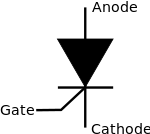 | |
A silicon controlled rectifier or semiconductor-controlled rectifier is a four-layer solid-state current-controlling device. The principle of four-layer p-n-p-n switching was developed by Moll, Tanenbaum, Goldey and Holonyak of Bell Laboratories in 1956.[1] The practical demonstration of silicon controlled switching and detailed theoretical behavior of a device in agreement with the experimental results was presented by Dr Ian M. Mackintosh of Bell Laboratories in January 1958.[2][3] The name "silicon controlled rectifier" is General Electric's trade name for a type of thyristor. The SCR was developed by a team of power engineers led by Gordon Hall[4] and commercialized by Frank W. "Bill" Gutzwiller in 1957.
Some sources define silicon controlled rectifiers and thyristors as synonymous,[5] other sources define silicon controlled rectifiers as a proper subset of the set of thyristors, those being devices with at least four layers of alternating n- and p-type material.[6][7] According to Bill Gutzwiller, the terms "SCR" and "controlled rectifier" were earlier, and "thyristor" was applied later, as usage of the device spread internationally.[8]
SCRs are unidirectional devices (i.e. can conduct current only in one direction) as opposed to TRIACs, which are bidirectional (i.e. current can flow through them in either direction). SCRs can be triggered normally only by currents going into the gate as opposed to TRIACs, which can be triggered normally by either a positive or a negative current applied to its gate electrode.
Construction
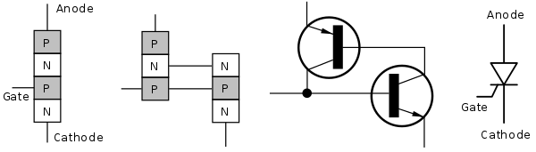
The silicon control rectifier (SCR) consists of four layers of semiconductors, which form NPNP or PNPN structures, having three P-N junctions labeled J1, J2 and J3, and three terminals. The anode terminal of an SCR is connected to the p-type material of a PNPN structure, and the cathode terminal is connected to the n-type layer, while the gate of the SCR is connected to the p-type material nearest to the cathode.[9]
An SCR consists of four layers of alternating p- and n-type semiconductor materials. Silicon is used as the intrinsic semiconductor, to which the proper dopants are added. The junctions are either diffused or alloyed (alloy is a mixed semiconductor or a mixed metal). The planar construction is used for low-power SCRs (and all the junctions are diffused). The mesa-type construction is used for high-power SCRs. In this case, junction J2 is obtained by the diffusion method, and then the outer two layers are alloyed to it, since the PNPN pellet is required to handle large currents. It is properly braced with tungsten or molybdenum plates to provide greater mechanical strength. One of these plates is hard-soldered to a copper stud, which is threaded for attachment of a heat sink. The doping of PNPN depends on the application of SCR, since its characteristics are similar to those of the thyristor. Today, the term "thyristor" applies to the larger family of multilayer devices that exhibit bistable state-change behaviour, that is, switching either on or off.
The operation of an SCR and other thyristors can be understood in terms of a pair of tightly coupled bipolar junction transistors, arranged to cause the self-latching action:
Modes of operation
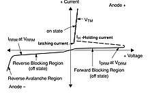
There are three modes of operation for an SCR depending upon the biasing given to it:
- Forward blocking mode (off state)
- Forward conduction mode (on state)
- Reverse blocking mode (off state)
Forward blocking mode
In this mode of operation, the anode (+) is given a positive voltage while the cathode (−) is given a negative voltage, keeping the gate at zero (0) potential i.e. disconnected. In this case junction J1 and J3 are forward-biased, while J2 is reverse-biased, due to which only a small leakage current exists from the anode to the cathode until the applied voltage reaches its breakover value, at which J2 undergoes avalanche breakdown, and at this breakover voltage it starts conducting, but below breakover voltage it offers very high resistance to the current and is said to be in the off state.
Forward conduction mode
An SCR can be brought from blocking mode to conduction mode in two ways: Either by increasing the voltage between anode and cathode beyond the breakover voltage, or by applying a positive pulse at the gate. Once the SCR starts conducting, no more gate voltage is required to maintain it in the ON state.
There are two ways to turn it off:
- Reduce the current through it below a minimum value called the holding current, or
- With the gate turned off, short-circuit the anode and cathode momentarily with a push-button switch or transistor across the junction.
Reverse blocking mode
When a negative voltage is applied to the anode and a positive voltage to the cathode, the SCR is in reverse blocking mode, making J1 and J3 reverse biased and J2 forward biased. The device behaves as two reverse-biassed diodes connected in series. A small leakage current flows. This is the reverse blocking mode. If the reverse voltage is increased, then at critical breakdown level, called the reverse breakdown voltage (VBR), an avalanche occurs at J1 and J3 and the reverse current increases rapidly. SCRs are available with reverse blocking capability, which adds to the forward voltage drop because of the need to have a long, low-doped P1 region. (If one cannot determine which region is P1, a labeled diagram of layers and junctions can help.) Usually, the reverse blocking voltage rating and forward blocking voltage rating are the same. The typical application for a reverse blocking SCR is in current-source inverters.
An SCR incapable of blocking reverse voltage is known as an asymmetrical SCR, abbreviated ASCR. It typically has a reverse breakdown rating in the tens of volts. ASCRs are used where either a reverse conducting diode is applied in parallel (for example, in voltage-source inverters) or where reverse voltage would never occur (for example, in switching power supplies or DC traction choppers).
Asymmetrical SCRs can be fabricated with a reverse conducting diode in the same package. These are known as RCTs, for reverse conducting thyristors.
Thyristor turn-on methods
- forward-voltage triggering
- gate triggering
- dv/dt triggering
- temperature triggering
- light triggering
Forward-voltage triggering occurs when the anode–cathode forward voltage is increased with the gate circuit opened. This is known as avalanche breakdown, during which junction J2 will break down. At sufficient voltages, the thyristor changes to its on state with low voltage drop and large forward current. In this case, J1 and J3 are already forward-biased.
Applications
SCRs are mainly used in devices where the control of high power, possibly coupled with high voltage, is demanded. Their operation makes them suitable for use in medium- to high-voltage AC power control applications, such as lamp dimming, power regulators and motor control.
SCRs and similar devices are used for rectification of high-power AC in high-voltage dc power transmission. They are also used in the control of welding machines, mainly GTAW (gas tungsten arc welding) processes similar. It is used as switch in various devices.
Compared to SCSs
A silicon controlled switch (SCS) behaves nearly the same way as an SCR; there are, however, a few differences: Unlike an SCR, an SCS switches off when a positive voltage/input current is applied to another anode gate lead. Unlike an SCR, an SCS can also be triggered into conduction when a negative voltage/output current is applied to that same lead.
SCSs are useful in practically all circuits that need a switch that turns on/off through two distinct control pulses. This includes power-switching circuits, logic circuits, lamp drivers, counters, etc.
Compared to TRIACs
A TRIAC resembles an SCR in that both act as electrically controlled switches. Unlike an SCR, a TRIAC can pass current in either direction. Thus, TRIACs are particularly useful for AC applications. TRIACs have three leads: a gate lead and two conducting leads, referred to as MT1 and MT2. If no current/voltage is applied to the gate lead, the TRIAC switches off. On the other hand, if the trigger voltage is applied to the gate lead, the TRIAC switches on.
TRIACs are suitable for light-dimming circuits, phase-control circuits, AC power-switching circuits, AC motor control circuits, etc.
See also
References
- ↑ Moll, J.; Tanenbaum, M.; Goldey, J.; Holonyak, N. (September 1956). "P-N-P-N Transistor Switches". Proceedings of the IRE. 44 (9): 1174–1182. doi:10.1109/jrproc.1956.275172. ISSN 0096-8390.
- ↑ Vasseur, J. P. (2016-06-06). Properties and Applications of Transistors. Elsevier. ISBN 9781483138886.
- ↑ Twist, Jo (2005-04-18). "Law that has driven digital life". BBC News. Retrieved 2018-07-27.
- ↑ Ward, Jack. "The Early History of the Silicon Controlled Rectifier". p. 6. Retrieved 12 April 2014.
- ↑ Christiansen, Donald; Alexander, Charles; Jurgen, Ronald (2005). Standard Handbook of Electronic Engineering, 5th Edition. Mcgraw-hill. ISBN 9780071384216.
- ↑ International Electrotechnical Commission 60747-6 standard
- ↑ Dorf, Richard C. (1997-09-26). The Electrical Engineering Handbook,Second Edition. CRC Press. ISBN 9781420049763.
- ↑ Ward, Jack. "The Early History of the Silicon Controlled Rectifier". p. 7. Retrieved 12 April 2014.
- ↑ "Silicon Controlled Rectifier - SCR". D&E Notes. 2017-12-15. Retrieved 2018-07-27.
Further reading
- ON Semiconductor (November 2006). Thyristor Theory and Design Considerations (PDF) (rev.1, HBD855/D ed.). p. 240.
- G. K. Mithal. Industrial and Power Electronics.
- K. B. Khanchandani. Power Electronics.