Darlington transistor
In electronics, the Darlington transistor (commonly called a Darlington pair) is a compound structure of a particular design made by two bipolar transistors connected in such a way that the current amplified by the first transistor is amplified further by the second one.[1] This configuration gives a much higher current gain than each transistor taken separately.
Invented in 1953 by Sidney Darlington.
Behavior
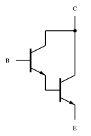
A Darlington pair behaves like a single transistor, meaning it has one base, collector, and emitter. It typically creates a high current gain (approximately the product of the gains of the two transistors, due to the fact that their β values multiply together). In fact, integrated devices have three leads (B, C, and E), broadly analogous to those of a standard transistor.
A general relation between the compound current gain and the individual gains is given by:

If β1 and β2 are high enough (hundreds), this relation can be approximated with:

Advantages
A typical Darlington transistor has a current gain of 1000 or more, so that only a small base current is needed to make the pair switch on higher switching currents.
Disadvantages
One drawback is an approximate doubling of the base–emitter voltage. Since there are two junctions between the base and emitter of the Darlington transistor, the equivalent base–emitter voltage is the sum of both base–emitter voltages:

For silicon-based technology, where each VBEi is about 0.65 V when the device is operating in the active or saturated region, the necessary base–emitter voltage of the pair is 1.3 V.
Another drawback of the Darlington pair is its increased "saturation" voltage. The output transistor is not allowed to saturate (i.e. its base–collector junction must remain reverse-biased) because the first transistor, when saturated, establishes full (100%) parallel negative feedback between the collector and the base of the second transistor.[2] Since collector–emitter voltage is equal to the sum of its own base–emitter voltage and the collector-emitter voltage of the first transistor, both positive quantities in normal operation, it always exceeds the base-emitter voltage. (In symbols, always.) Thus the "saturation" voltage of a Darlington transistor is one VBE (about 0.65 V in silicon) higher than a single transistor saturation voltage, which is typically 0.1 - 0.2 V in silicon. For equal collector currents, this drawback translates to an increase in the dissipated power for the Darlington transistor over a single transistor. The increased low output level can cause troubles when TTL logic circuits are driven.

Another problem is a reduction in switching speed or response, because the first transistor cannot actively inhibit the base current of the second one, making the device slow to switch off. To alleviate this, the second transistor often has a resistor of a few hundred ohms connected between its base and emitter terminals.[1] This resistor provides a low-impedance discharge path for the charge accumulated on the base-emitter junction, allowing a faster transistor turn-off.
The Darlington pair has more phase shift at high frequencies than a single transistor and hence can more easily become unstable with negative feedback (i.e., systems that use this configuration can have poor phase margin due to the extra transistor delay).
Packaging
Integrated devices can take less space than two individual transistors because they can use a shared collector. Integrated Darlington pairs come packaged singly in transistor-like packages or as an array of devices (usually eight) in an integrated circuit.
Darlington pairs are available as integrated packages or can be made from two discrete transistors; Q1, the left-hand transistor in the diagram, can be a low power type, but normally Q2 (on the right) will need to be high power. The maximum collector current IC(max) of the pair is that of Q2. A typical integrated power device is the 2N6282, which includes a switch-off resistor and has a current gain of 2400 at IC=10A.
Applications
Safety
A Darlington pair can be sensitive enough to respond to the current passed by skin contact even at safe voltages. Thus it can form the input stage of a touch-sensitive switch.
Amplification
Darlington transistors can be used in high-current circuits, such as those involving computer control of motors or relays. The current is amplified from the normal low level of the computer output line to the amount needed by the connected device.
See also
- Insulated-gate bipolar transistor
- ULN2003A
- Sziklai pair, sometimes called the "complementary Darlington", a similar configuration but with transistors of opposite type (one NPN and one PNP)
References
- 1 2 Horowitz, Paul; Winfield Hill (1989). The Art of Electronics. Cambridge University Press. ISBN 0-521-37095-7.
- ↑ Similarly, an emitter follower never saturates because of the 100% series negative feedback. Another example is an "active diode" made by a transistor with joined base and collector (e.g., the current-setting part of a current mirror).
External links
- U.S. Patent 2,663,806 "Semiconductor signal translating device" (Darlington transistor)
- A Darlington pair motor speed control circuit
- ECE 327: Procedures for Output Filtering Lab – Section 4 ("Power Amplifier") discusses Darlington pairs in the design of a BJT-based class-AB current driver in detail.
.svg.png)