Gyrotron
A gyrotron is a class of high-power linear-beam vacuum tubes which generates millimeter-wave electromagnetic waves by the cyclotron resonance of electrons in a strong magnetic field. Output frequencies range from about 20 to 527 GHz,[1][2] covering wavelengths from microwave to the edge of the terahertz gap. Typical output powers range from tens of kilowatts to 1–2 megawatts. Gyrotrons can be designed for pulsed or continuous operation.
Principle of operation

The gyrotron is a type of free-electron maser which generates high-frequency electromagnetic radiation by stimulated cyclotron resonance of electrons moving through a strong magnetic field.[3][4] It can produce high power at millimeter wavelengths because as a fast-wave device its dimensions can be much larger than the wavelength of the radiation. This is unlike conventional microwave vacuum tubes such as klystrons and magnetrons, in which the wavelength is determined by a single-mode resonant cavity, a slow-wave structure, and thus as operating frequencies increase, the resonant cavity structures must decrease in size, which limits their power-handling capability.
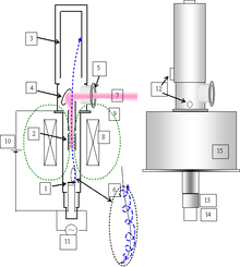
In the gyrotron a hot filament in an electron gun at one end of the tube emits an annular-shaped (hollow tubular) beam of electrons, which is accelerated by a high-voltage anode and then travels through a large tubular resonant cavity structure in a strong axial magnetic field, usually created by a superconducting magnet around the tube. The field causes the electrons to move helically in tight circles around the magnetic field lines as they travel lengthwise through the tube. At the position in the tube where the magnetic field reaches its maximum the electrons radiate electromagnetic waves in a transverse direction (perpendicular to the axis of the tube) at their cyclotron resonance frequency. The millimeter radiation forms standing waves in the tube, which acts as an open-ended resonant cavity, and is formed into a beam, which radiates through a window in the side of the tube into a waveguide. The spent electron beam is absorbed by a collector electrode at the end of the tube.
As in other linear-beam microwave tubes, the energy of the output electromagnetic waves comes from the kinetic energy of the electron beam, which is due to the accelerating anode voltage. In the region before the resonant cavity where the magnetic field strength is increasing, it compresses the electron beam, converting the longitudinal drift velocity to transverse orbital velocity, in a process similar to that occurring in a magnetic mirror used in plasma confinement.[4] The orbital velocity of the electrons is 1.5 to 2 times their axial beam velocity. Due to the standing waves in the resonant cavity, the electrons become "bunched"; that is, their phase becomes coherent (synchronized) so they are all at the same point in their orbit at the same time. Therefore, they emit coherent radiation.
The electron speed in a gyrotron is slightly relativistic (comparable to but not close to the speed of light). This contrasts to the free-electron laser (and xaser) that work on different principles and whose electrons are highly relativistic.
Applications
Gyrotrons are used for many industrial and high-technology heating applications. For example, gyrotrons are used in nuclear fusion research experiments to heat plasmas and also in manufacturing industry as a rapid heating tool in processing glass, composites, and ceramics, as well as for annealing (solar and semiconductors). Military applications include the Active Denial System.
Types
The output window of the tube from which the microwave beam emerges can be in two locations
- Transverse-output gyrotron: The beam exits by a window in the side of the tube. This requires a 45° mirror at the end of the cavity to reflect the microwave beam, positioned at one side so the electron beam misses it. This type is shown in the diagram above.
- Axial-output gyrotron: The beam exits by a window in the end of the tube, at the far end of the cylindrical collector electrode which collects the electrons.
The original gyrotron described above, developed in 1964, was an oscillator, but since that time gyrotron amplifiers have been developed. The helical gyrotron electron beam can amplify an applied microwave signal similarly to the way a straight electron beam amplifies in classical microwave tubes such as the klystron, so there are a series of gyrotrons which function analogously to these tubes. Their advantage is that they can operate at much higher frequencies:
- Gyro-monotron or Gyro-oscillator: Single-cavity gyrotron described above functions as an oscillator
- Gyro-klystron: Amplifier that functions analogously to a klystron tube. Has two microwave cavities along the electron beam, an input cavity upstream to which the signal to be amplified is applied and an output cavity downstream from which the output is taken.
- Gyro-TWT: Amplifier that functions analogously to a travelling wave tube (TWT). Has a slow wave structure similar to a TWT paralleling the beam, with the input microwave signal applied to the upstream end and the amplified output signal taken from the downstream end.
- Gyro-BWO: Oscillator that functions analogously to a backward wave oscillator (BWO). Generates oscillations traveling in an opposite direction to the electron beam, which are output at the upstream end of the tube.
- Gyro-twystron: Amplifier that functions analogouly to a twystron, a tube that combines a klystron and a TWT. Like a klystron it has an input cavity at the upstream end followed by buncher cavities to bunch the electrons, which are followed by a TWT type slow-wave structure which develops the amplified output signal. Like a TWT it can have a wide bandwidth.
Manufacturers
The gyrotron was invented in the Soviet Union.[5] Present makers include Communications & Power Industries (USA), Gycom (Russia), Thales Group (EU), Toshiba (Japan), and Bridge12 Technologies, Inc.. System developers include Gyrotron Technology, Inc.
See also
References
- ↑ Richards, Mark A.; William A. Holm (2010). "Power Sources and Amplifiers". Principles of Modern Radar: Basic Principles. SciTech Pub., 2010. p. 360. ISBN 1891121529.
- ↑ Blank, M.; Borchard, P.; Cauffman, S.; Felch, K.; Rosay, M.; Tometich, L. (2013-06-01). "Experimental demonstration of a 527 GHz gyrotron for dynamic nuclear polarization". 2013 Abstracts IEEE International Conference on Plasma Science (ICOPS): 1–1. doi:10.1109/PLASMA.2013.6635226.
- ↑ "What is a Gyrotron?". Learn about DNP-NMR spectroscopy. Bridge 12 Technologies. Retrieved July 9, 2014.
- 1 2 Borie, E. (c. 1990). "Review of Gyrotron Theory" (PDF). KfK 4898. Institut für Technische Physik, Kernforschungszentrum Karlsruhe (Karlsruhe Institute of Technology), Karlsruhe, Germany. Retrieved July 9, 2014.
- ↑ National Research Council (U.S.). Panel on High Magnetic Field Research and Facilities (1979). "Defense Technology - High Frequency Radiation". High-Magnetic-Field Research and Facilities. Washington, D.C.: National Academy of Sciences. pp. 50–51. OCLC 13876197.
External links
- Gyrotron
- Kupiszezwki, A. (1979). "The Gyrotron: A High Frequency Microwave Amplifier" (pdf). The Deep Space Network Progress Report. NASA JPL. 42 (52): 8–12. Bibcode:1979dsn..nasa....8K. NASA Code 310-10-64-10.