Diode bridge
A diode bridge is an arrangement of four (or more) diodes in a bridge circuit configuration that provides the same polarity of output for either polarity of input.
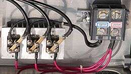
 Diode bridge in various packages | |
| Type | Semiconductor |
|---|---|
| Invented | Karol Pollak in 1895 |
| Electronic symbol | |
 2 alternating-current (AC) inputs converted into 2 direct-current (DC) outputs | |

When used in its most common application, for conversion of an alternating-current (AC) input into a direct-current (DC) output, it is known as a bridge rectifier. A bridge rectifier provides full-wave rectification from a two-wire AC input, resulting in lower cost and weight as compared to a rectifier with a 3-wire input from a transformer with a center-tapped secondary winding.[1]
The essential feature of a diode bridge is that the polarity of the output is the same regardless of the polarity at the input. The diode bridge circuit was invented by Polish electrotechnician Karol Pollak and patented in December 1895 in Great Britain[2] and in January 1896 in Germany[3][4]. In 1897, the German physicist Leo Graetz independently invented and published a similar circuit.[5][6] Today the circuit is still referred to as a Graetz circuit or Graetz bridge.[7]
Prior to the availability of integrated circuits, a bridge rectifier was constructed from "discrete components", i.e., separate diodes. Since about 1950, a single four-terminal component containing the four diodes connected in a bridge configuration became a standard commercial component and is now available with various voltage and current ratings.
Diodes are also used in bridge topologies along with capacitors as voltage multipliers.
Current flow
According to the conventional model of current flow (originally established by Benjamin Franklin and still followed by most engineers today[8]), current flows through electrical conductors from the positive to the negative pole (defined as "positive flow"). In actuality, free electrons in a conductor nearly always flow from the negative to the positive pole. In the vast majority of applications, however, the actual direction of current flow is irrelevant. Therefore, in the discussion below the conventional model is retained.
The fundamental characteristic of a diode is that current can flow only one way through it, which is defined as the forward direction. A diode bridge uses diodes as series components to allow current to pass in the forward direction during the positive part of the AC cycle and as shunt components to redirect current flowing in the reverse direction during the negative part of the AC cycle to the opposite rails.
Rectifier
In the diagrams below, when the input connected to the left corner of the diamond is positive, and the input connected to the right corner is negative, current flows from the upper supply terminal to the right along the red (positive) path to the output and returns to the lower supply terminal through the blue (negative) path.

When the input connected to the left corner is negative, and the input connected to the right corner is positive, current flows from the lower supply terminal to the right along the red (positive) path to the output and returns to the upper supply terminal through the blue (negative) path.[9]
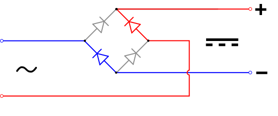
In each case, the upper right output remains positive[10], and lower right output negative. Since this is true whether the input is AC or DC, this circuit not only produces a DC output from an AC input, it can also provide what is sometimes called "reverse-polarity protection". That is, it permits normal functioning of DC-powered equipment when batteries have been installed backwards, or when the leads (wires) from a DC power source have been reversed, and protects the equipment from potential damage caused by reverse polarity.
Alternatives to the diode-bridge full-wave rectifiers are the center-tapped transformer and double-diode rectifier, and voltage doubler rectifier using two diodes and two capacitors in a bridge topology.
Smoothing circuits
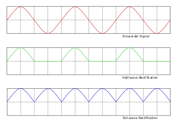
With AC input, the output of a diode bridge (called a full-wave rectifier for this purpose; there is also half-wave rectification, which does not use a diode bridge) is polarized pulsating non-sinusoidal voltage of the same amplitude but twice the frequency of the input. It may be considered as DC voltage upon which is superimposed a very large ripple voltage. This kind of electric power is not very usable, because ripple is dissipated as waste heat in DC circuit components and may cause noise or distortion during circuit operation. So nearly all rectifiers are followed by a series of bandpass or bandstop filters and/or a voltage regulator to convert most or all of the ripple voltage into a smoother and possibly higher DC output. A filter may be as simple as a single sufficiently large capacitor or choke, but most power-supply filters have multiple alternating series and shunt components. When the ripple voltage rises, reactive power is stored in the filter components, reducing the voltage; when the ripple voltage falls, reactive power is discharged from the filter components, raising the voltage. The final stage of rectification may consist of a zener diode-based voltage regulator, which almost completely eliminates any residual ripple.
Snubber circuits
Power-supply transformers have leakage inductance and parasitic capacitance. When the diodes in a bridge rectifier switch off, these "non-ideal" elements form a resonant circuit, which can oscillate at high frequency. This high-frequency oscillation can then couple into the rest of the circuitry. Snubber circuits are used in an attempt to mitigate this problem. A snubber circuit consists of either a very small capacitor or series capacitor and resistor across a diode.
Polyphase diode bridges
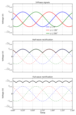
The diode bridge can be generalized to rectify polyphase AC inputs. For example, for a three-phase AC input, a half-wave rectifier consists of three diodes, but a full-wave bridge rectifier consists of six diodes.
Half-wave rectifier may be considered as wye connection (star connection), because it returns the current through the centre (neutral) wire. Full-wave is more like delta connection, although it can be connected to the three-phase source of either wye or delta and it does not use the centre (neutral) wire.

See also
- 1N400x general-purpose diodes also called rectifier diodes
- Active rectification
- HVDC converter
References
- Horowitz, Paul; Hill, Winfield (1989). The Art of Electronics (Second ed.). Cambridge University Press. pp. 44–47. ISBN 0-521-37095-7.
- British patent 24398.
- (Graetz, 1897), p. 327 footnote.
- (Editorial staff) (24 June 1897). "Ein neues Gleichrichter-Verfahren" [A new method of rectification]. Elektrotechnische Zeitschrift (in German). 18 (25): 359 and footnote.
- See:
- Graetz, L. (1 May 1897). "Electrochemisches Verfahren, um Wechselströme in Gleichströme zu verwandeln" [Electrochemical method of changing alternating into direct currents]. Sitzungsberichte der Mathematisch-Physikalischen Classe der Königlich Bayerischen Akademie der Wissenschaften zu München (Transactions of the Mathematical-Physical Classes of the Royal Bavarian Academy of Sciences in Munich) (in German). 27: 223–228.
- Graetz, L. (1897). "Electrochemisches Verfahren, um Wechselströme in Gleichströme zu verwandeln" [Electrochemical method of changing alternating into direct currents]. Annalen der Physik und Chemie. 3rd series (in German). 62: 323–327.
- Graetz, Leo (22 July 1897). "Electrochemisches Verfahren, um Wechselströme in Gleichströme zu verwandeln" [Electrochemical method of changing alternating into direct currents]. Elektrotechnische Zeitschrift (in German). 18 (29): 423–424.
- Strzelecki, R. Power Electronics in Smart Electrical Energy Networks. Springer, 2008, p. 57.
- "Graetz Flow Control Circuit". Archived from the original on 2013-11-04.
- Stutz, Michael (stutz@dsl.org), "Conventional versus electron flow", All About Circuits, Vol. 1, Chapter 1, 2000.
- Sears, Francis W., Mark W. Zemansky and Hugh D. Young, University Physics, Sixth Ed., Addison-Wesely Publishing Co., Inc., 1982, p. 685.
- The Geek Pub https://www.thegeekpub.com/243767/bridge-rectifier-circuit-electronics-basics/. Retrieved 3 September 2019. Missing or empty
|title=(help) - "Rectifier", Concise Encyclopedia of Science and Technology, Third Edition, Sybil P. Parker, ed. McGraw-Hill, Inc., 1994, p. 1589.
External links
| Wikimedia Commons has media related to Bridge rectifiers. |
- "Electronics: Bridge Rectifiers (1969) US Air Force Training Film". Old Movies Reborn (Youtube). July 16, 2017.