Axonometric projection
Axonometric projection is a type of orthographic projection used for creating a pictorial drawing of an object, where the lines of sight are perpendicular to the plane of projection, and the object is rotated around one or more of its axes to reveal multiple sides.[1]
Overview
"Axonometry" means "to measure along axes". In German literature, axonometry is based on Pohlke's theorem, so that the scope of axonometric projection encompasses every type of parallel projection, including not only oblique projection, but also orthographic projection and therefore multiview projection. However, outside of German literature, the term "axonometric" is often used to make an explicit distinction from multiview projection, because axonometric projection allows for the depiction of more than one "side" of an object, whereas a multiview projection allows for the depiction of only one "side" of an object:
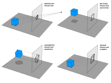
- A multiview projection depicts an object from one of six primary views (e.g. front, right, left, top, bottom, or back); one of the principal axes of the object (e.g., the z or "depth" axis) is necessarily perpendicular to the projection plane, and thus such a projection can depict only one "side" of the object. Because multiview projections are a fundamental facet of technical illustration, a depiction that results from another type of projection is often called an "auxiliary" view.
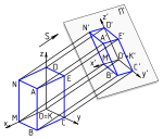
- In contrast, an axonometric projection may depict an object such that none of the principal axes of the object is perpendicular to the projection plane, and thus more than one "side" of an object may be represented simultaneously (that is to say, the z or "depth" axis may be represented); usually, the projection is such that the images of any 2 axes are not collinear, so that the angles between projected lines help to distinguish each dimension. when it is possible to depict more than one side of an object, it may be said that the object is being viewed from a "skew" angle.
Furthermore, in English literature, the term "axonometric projection" typically implies an orthographic projection, such as an isometric projection.
With an axonometric projection, the scale of an object does not depend on its location along any particular axis (an object in the "foreground" has the same scale as an object in the "background"); consequently, such pictures look distorted, because human vision or photography uses perspective projection, in which the scale of an object depends on its location along one of the axes (e.g., the z or "depth" axis). This distortion, the direct result of a presence or absence of foreshortening, is especially evident if the object is mostly composed of rectangular features. Despite this limitation, axonometric projection can be useful for purposes of illustration, especially because it allows for simultaneously relaying precise measurements.
Three types
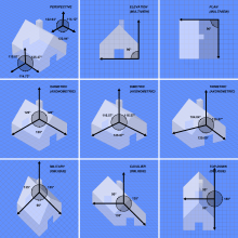

The three types of axonometric projection are isometric projection, dimetric projection, and trimetric projection, depending on the exact angle at which the view deviates from the orthogonal.[2][3] Typically in axonometric drawing, as in other types of pictorials, one axis of space is shown as the vertical.
In isometric projection, the most commonly used form of axonometric projection in engineering drawing,[4] the direction of viewing is such that the three axes of space appear equally foreshortened, and there is a common angle of 120° between them. As the distortion caused by foreshortening is uniform, the proportionality between lengths is preserved, and the axes share a common scale; this eases the ability to take measurements directly from the drawing. Another advantage is that 120° angles are easily constructed using only a compass and straightedge.
In dimetric projection, the direction of viewing is such that two of the three axes of space appear equally foreshortened, of which the attendant scale and angles of presentation are determined according to the angle of viewing; the scale of the third direction is determined separately. Dimensional approximations are common in dimetric drawings.
In trimetric projection, the direction of viewing is such that all of the three axes of space appear unequally foreshortened. The scale along each of the three axes and the angles among them are determined separately as dictated by the angle of viewing. Dimensional approximations in trimetric drawings are common, and trimetric perspective is seldom used in technical drawings.[3]
History
The concept of isometry had existed in a rough empirical form for centuries, well before Professor William Farish (1759–1837) of Cambridge University was the first to provide detailed rules for isometric drawing.[5][6]
Farish published his ideas in the 1822 paper "On Isometrical Perspective", in which he recognized the "need for accurate technical working drawings free of optical distortion. This would lead him to formulate isometry. Isometry means "equal measures" because the same scale is used for height, width, and depth".[7]
From the middle of the 19th century, according to Jan Krikke (2006)[7] isometry became an "invaluable tool for engineers, and soon thereafter axonometry and isometry were incorporated in the curriculum of architectural training courses in Europe and the U.S. The popular acceptance of axonometry came in the 1920s, when modernist architects from the Bauhaus and De Stijl embraced it".[7] De Stijl architects like Theo van Doesburg used axonometry for their architectural designs, which caused a sensation when exhibited in Paris in 1923".[7]
Since the 1920s axonometry, or parallel perspective, has provided an important graphic technique for artists, architects, and engineers. Like linear perspective, axonometry helps depict three-dimensional space on a two-dimensional picture plane. It usually comes as a standard feature of CAD systems and other visual computing tools.[8]
According to Jan Krikke (2000), "axonometry originated in China. Its function in Chinese art was similar to linear perspective in European art. Axonometry, and the pictorial grammar that goes with it, has taken on a new significance with the advent of visual computing".[8]
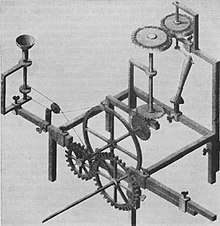 Optical-grinding engine model (1822), drawn in 30° isometric perspective[9]
 Example of a dimetric perspective drawing from a US Patent (1874)
 Example of a trimetric projection showing the shape of the Bank of China Tower in Hong Kong.
 Example of dimetric projection in Chinese art in an illustrated edition of the Romance of the Three Kingdoms, China, c. 15th century CE.
.jpg) Detail of the original version of Along the River During the Qingming Festival attributed to Zhang Zeduan (1085–1145). Note that the picture switches back and forth between axonometric and perspective projection in different parts of the image, and is thus inconsistent.
Detail of the original version of Along the River During the Qingming Festival attributed to Zhang Zeduan (1085–1145). Note that the picture switches back and forth between axonometric and perspective projection in different parts of the image, and is thus inconsistent.
Limitations
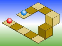
As with all types of parallel projection, objects drawn with axonometric projection do not appear larger or smaller as they lie closer to or farther away from the viewer. While advantageous for architectural drawings, where measurements must be taken directly from the image, the result is a perceived distortion, since unlike perspective projection, this is not how human vision or photography normally works. It also can easily result in situations where depth and altitude are difficult to gauge, as is shown in the illustration to the right.
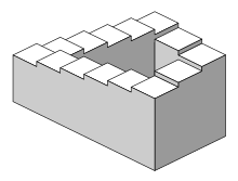
This visual ambiguity has been exploited in op art, as well as "impossible object" drawings. Though not strictly axonometric, M. C. Escher's Waterfall (1961) is a well-known image, in which a channel of water seems to travel unaided along a downward path, only to then paradoxically fall once again as it returns to its source. The water thus appears to disobey the law of conservation of energy.
References
- ↑ Gary R. Bertoline et al. (2002) Technical Graphics Communication. McGraw–Hill Professional, 2002. ISBN 0-07-365598-8, p. 330.
- ↑ Maynard, Patric (2005). Drawing distinctions: the varieties of graphic expression. Cornell University Press. p. 22. ISBN 0-8014-7280-6.
- 1 2 McReynolds, Tom; David Blythe (2005). Advanced graphics programming using openGL. Elsevier. p. 502. ISBN 1-55860-659-9.
- ↑ Godse, A. P. (1984). Computer graphics. Technical Publications. p. 29. ISBN 81-8431-558-9.
- ↑ Barclay G. Jones (1986). Protecting historic architecture and museum collections from natural disasters. University of Michigan. ISBN 0-409-90035-4. p. 243.
- ↑ Charles Edmund Moorhouse (1974). Visual messages: graphic communication for senior students.
- 1 2 3 4 J. Krikke (1996). "A Chinese perspective for cyberspace?". In: International Institute for Asian Studies Newsletter, 9, Summer 1996.
- 1 2 Jan Krikke (2000). "Axonometry: a matter of perspective". In: Computer Graphics and Applications, IEEE Jul/Aug 2000. Vol 20 (4), pp. 7–11.
- ↑ William Farish (1822) "On Isometrical Perspective". In: Cambridge Philosophical Transactions. 1 (1822).
Further reading
| Wikimedia Commons has media related to Axonometric projection. |
- Yve-Alain Bois, "Metamorphosis of Axonometry," Daidalos, no. 1 (1981), pp. 41–58