Graphical projection
Graphical projection is a protocol, used in technical drawing, by which an image of a three-dimensional object is projected onto a planar surface without the aid of numerical calculation.
Overview
The projection is achieved by the use of imaginary "projectors". The projected, mental image becomes the technician’s vision of the desired, finished picture. By following the protocol the technician may produce the envisioned picture on a planar surface such as drawing paper. The protocols provide a uniform imaging procedure among people trained in technical graphics (mechanical drawing, computer aided design, etc.).
There are two graphical projection categories each with its own protocol:
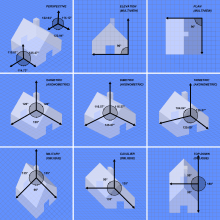
 Multiview projection (elevation)
 Oblique projection (military)
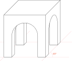 Oblique projection (cabinet)
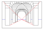
Parallel projection
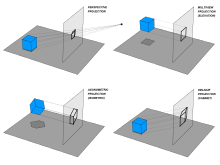
In parallel projection, the lines of sight from the object to the projection plane are parallel to each other. Thus, lines that are parallel in three-dimensional space remain parallel in the two-dimensional projected image. Parallel projection also corresponds to a perspective projection with an infinite focal length (the distance from a camera's lens and focal point), or "zoom".
Images drawn in parallel projection rely upon the technique of axonometry ("to measure along axes"), as described in Pohlke's theorem. In general, the resulting image is oblique (the rays are not perpendicular to the image plane); but in special cases the result is orthographic (the rays are perpendicular to the image plane). Axonometry should not be confused with axonometric projection, as in English literature the latter usually refers only to a specific class of pictorials (see below).
Orthographic projection
The orthographic projection is derived from the principles of descriptive geometry and is a two-dimensional representation of a three-dimensional object. It is a parallel projection (the lines of projection are parallel both in reality and in the projection plane). It is the projection type of choice for working drawings.
Multiview projection

With multiview projections, up to six pictures (called primary views) of an object are produced, with each projection plane parallel to one of the coordinate axes of the object. The views are positioned relative to each other according to either of two schemes: first-angle or third-angle projection. In each, the appearances of views may be thought of as being projected onto planes that form a 6-sided box around the object. Although six different sides can be drawn, usually three views of a drawing give enough information to make a 3D object. These views are known as front view, top view and end view. The terms elevation, plan and section are also used.
Axonometric projection

Within orthographic projection there is an ancillary category known as orthographic pictorial or axonometric projection. Axonometric projections show an image of an object as viewed from a skew direction in order to reveal all three directions (axes) of space in one picture.[1] Axonometric instrument drawings are often used to approximate graphical perspective projections, but there is attendant distortion in the approximation. Because pictorial projections innately contain this distortion, in instrument drawings of pictorials great liberties may then be taken for economy of effort and best effect.
Axonometric projection is further subdivided into three categories: isometric projection, dimetric projection and trimetric projection, depending on the exact angle at which the view deviates from the orthogonal.[2][3] A typical characteristic of orthographic pictorials is that one axis of space is usually displayed as vertical.
Axonometric projections are also sometimes known as auxiliary views, as opposed to the primary views of multiview projections.
Isometric projection
In isometric pictorials (for protocols see isometric projection), the direction of viewing is such that the three axes of space appear equally foreshortened, and there is a common angle of 120° between them. As the distortion caused by foreshortening is uniform the proportionality of all sides and lengths are preserved, and the axes share a common scale. This enables measurements to be read or taken directly from the drawing.
Dimetric projection
In dimetric pictorials (for protocols see dimetric projection), the direction of viewing is such that two of the three axes of space appear equally foreshortened, of which the attendant scale and angles of presentation are determined according to the angle of viewing; the scale of the third direction (vertical) is determined separately. Approximations are common in dimetric drawings.
Trimetric projection
In trimetric pictorials (for protocols see trimetric projection), the direction of viewing is such that all of the three axes of space appear unequally foreshortened. The scale along each of the three axes and the angles among them are determined separately as dictated by the angle of viewing. Approximations in Trimetric drawings are common.
Oblique projection

In oblique projections the parallel projection rays are not perpendicular to the viewing plane as with orthographic projection, but strike the projection plane at an angle other than ninety degrees. In both orthographic and oblique projection, parallel lines in space appear parallel on the projected image. Because of its simplicity, oblique projection is used exclusively for pictorial purposes rather than for formal, working drawings. In an oblique pictorial drawing, the displayed angles among the axes as well as the foreshortening factors (scale) are arbitrary. The distortion created thereby is usually attenuated by aligning one plane of the imaged object to be parallel with the plane of projection thereby creating a true shape, full-size image of the chosen plane. Special types of oblique projections are:
Cavalier projection
In cavalier projection (sometimes cavalier perspective or high view point) a point of the object is represented by three coordinates, x, y and z. On the drawing, it is represented by only two coordinates, x″ and y″. On the flat drawing, two axes, x and z on the figure, are perpendicular and the length on these axes are drawn with a 1:1 scale; it is thus similar to the dimetric projections, although it is not an axonometric projection, as the third axis, here y, is drawn in diagonal, making an arbitrary angle with the x″ axis, usually 30 or 45°. The length of the third axis is not scaled.
Cabinet projection
The term cabinet projection (sometimes cabinet perspective) stems from its use in illustrations by the furniture industry. Like cavalier perspective, one face of the projected object is parallel to the viewing plane, and the third axis is projected as going off in an angle (typically 30° or 45° or arctan(2)= 63.4°). Unlike cavalier projection, where the third axis keeps its length, with cabinet projection the length of the receding lines is cut in half.
Military projection
A variant of oblique projection is called military projection. In this case the horizontal sections are isometrically drawn so that the floor plans are not distorted and the verticals are drawn at an angle. The military projection is given by rotation in the xy-plane and a vertical translation an amount z. [4]
Limitations of parallel projection
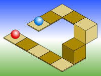
Objects drawn with parallel projection do not appear larger or smaller as they extend closer to or away from the viewer. While advantageous for architectural drawings, where measurements must be taken directly from the image, the result is a perceived distortion, since unlike perspective projection, this is not how our eyes or photography normally work. It also can easily result in situations where depth and altitude are difficult to gauge, as is shown in the illustration to the right.
In this isometric drawing, the blue sphere is two units higher than the red one. However, this difference in elevation is not apparent if one covers the right half of the picture, as the boxes (which serve as clues suggesting height) are then obscured.
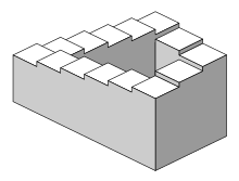
This visual ambiguity has been exploited in op art, As well as "impossible object" drawings. M. C. Escher's Waterfall (1961), while not strictly using parallel projection, is a well-known example, in which a channel of water seems to travel unaided along a downward path, only to then paradoxically fall once again as it returns to its source. The water thus appears to disobey the law of conservation of energy. An extreme example is depicted in the film Inception, where by a forced perspective trick an immobile stairway changes its connectivity.
Perspective projection

Perspective projection is a linear projection where three dimensional objects are projected on a picture plane. This has the effect that distant objects appear smaller than nearer objects.
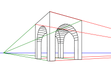
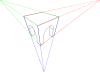
It also means that lines which are parallel in nature (that is, meet at the point at infinity) appear to intersect in the projected image, for example if railways are pictured with perspective projection, they appear to converge towards a single point, called vanishing point. Photographic lenses and the human eye work in the same way, therefore perspective projection looks most realistic.[5] Perspective projection is usually categorized into one-point, two-point and three-point perspective, depending on the orientation of the projection plane towards the axes of the depicted object.[6]
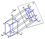
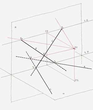
Graphical projection methods rely on the duality between lines and points, whereby two straight lines determine a point while two points determine a straight line. The orthogonal projection of the eye point onto the picture plane is called the principal vanishing point (P.P. in the scheme on the left, from the Italian term punto principale, coined during the renaissance).[7]
Two relevant points of a line are:
- its intersection with the picture plane, and
- its vanishing point, found at the intersection between the parallel line from the eye point and the picture plane.
The principal vanishing point is the vanishing point of all horizontal lines perpendicular to the picture plane. The vanishing points of all horizontal lines lie on the horizon line. If, as is often the case, the picture plane is vertical, all vertical lines are drawn vertically, and have no finite vanishing point on the picture plane. Various graphical methods can be easily envisaged for projecting geometrical scenes. For example, lines traced from the eye point at 45° to the picture plane intersect the latter along a circle whose radius is the distance of the eye point from the plane, thus tracing that circle aids the construction of all the vanishing points of 45° lines; in particular, the intersection of that circle with the horizon line consists of two distance points. They are useful for drawing chessboard floors which, in turn, serve for locating the base of objects on the scene. In the perspective of a geometric solid on the right, after choosing the principal vanishing point —which determines the horizon line— the 45° vanishing point on the left side of the drawing completes the characterization of the (equally distant) point of view. Two lines are drawn from the orthogonal projection of each vertex, one at 45° and one at 90° to the picture plane. After intersecting the ground line, those lines go toward the distance point (for 45°) or the principal point (for 90°). Their new intersection locates the projection of the map. Natural heights are measured above the ground line and then projected in the same way until they meet the vertical from the map.
See also
| Wikimedia Commons has media related to Graphical projection. |
References
- ↑ Mitchell, William; Malcolm McCullough (1994). Digital design media. John Wiley and Sons. p. 169. ISBN 0-471-28666-4.
- ↑ Maynard, Patric (2005). Drawing distinctions: the varieties of graphic expression. Cornell University Press. p. 22. ISBN 0-8014-7280-6.
- ↑ McReynolds, Tom; David Blythe (2005). Advanced graphics programming using openGL. Elsevier. p. 502. ISBN 1-55860-659-9.
- ↑ "Axonometric projections - a technical overview". Retrieved 24 April 2015.
- ↑ D. Hearn, & M. Baker (1997). Computer Graphics, C Version. Englewood Cliffs: Prentice Hall], chapter 9
- ↑ James Foley (1997). Computer Graphics. Boston: Addison-Wesley. ISBN 0-201-84840-6], chapter 6
- ↑ Kirsti Andersen (2007), The geometry of an art, Springer, ISBN 9780387259611