Track (rail transport)
The track on a railway or railroad, also known as the permanent way, is the structure consisting of the rails, fasteners, railroad ties (sleepers, British English) and ballast (or slab track), plus the underlying subgrade. It enables trains to move by providing a dependable surface for their wheels to roll upon. For clarity it is often referred to as railway track (British English and UIC terminology) or railroad track (predominantly in the United States). Tracks where electric trains or electric trams run are equipped with an electrification system such as an overhead electrical power line or an additional electrified rail.
| Track gauge | ||||||||||||||||||||||||||||||||||||||||||||||||||||||||||||||||||||||||||||||||||||||||
|---|---|---|---|---|---|---|---|---|---|---|---|---|---|---|---|---|---|---|---|---|---|---|---|---|---|---|---|---|---|---|---|---|---|---|---|---|---|---|---|---|---|---|---|---|---|---|---|---|---|---|---|---|---|---|---|---|---|---|---|---|---|---|---|---|---|---|---|---|---|---|---|---|---|---|---|---|---|---|---|---|---|---|---|---|---|---|---|---|
| By transport mode | ||||||||||||||||||||||||||||||||||||||||||||||||||||||||||||||||||||||||||||||||||||||||
|
Tram · Rapid transit Miniature · Scale model |
||||||||||||||||||||||||||||||||||||||||||||||||||||||||||||||||||||||||||||||||||||||||
| By size (list) | ||||||||||||||||||||||||||||||||||||||||||||||||||||||||||||||||||||||||||||||||||||||||
|
||||||||||||||||||||||||||||||||||||||||||||||||||||||||||||||||||||||||||||||||||||||||
| Change of gauge | ||||||||||||||||||||||||||||||||||||||||||||||||||||||||||||||||||||||||||||||||||||||||
|
Break-of-gauge · Dual gauge · Conversion (list) · Bogie exchange · Variable gauge |
||||||||||||||||||||||||||||||||||||||||||||||||||||||||||||||||||||||||||||||||||||||||
| By location | ||||||||||||||||||||||||||||||||||||||||||||||||||||||||||||||||||||||||||||||||||||||||
|
North America · South America · Europe · Australia  |
||||||||||||||||||||||||||||||||||||||||||||||||||||||||||||||||||||||||||||||||||||||||

The term permanent way also refers to the track in addition to lineside structures such as fences.
Structure
Sometimes there is a layer of rubber matting (not shown) to improve drainage, and to dampen sound and vibration
Traditional track structure
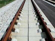
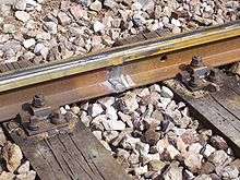
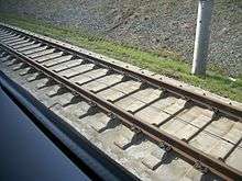
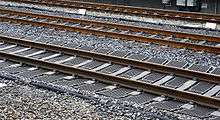
Notwithstanding modern technical developments, the overwhelmingly dominant track form worldwide consists of flat-bottom steel rails supported on timber or pre-stressed concrete sleepers, which are themselves laid on crushed stone ballast.
Most railroads with heavy traffic utilize continuously welded rails supported by sleepers attached via base plates that spread the load. A plastic or rubber pad is usually placed between the rail and the tie plate where concrete sleepers are used. The rail is usually held down to the sleeper with resilient fastenings, although cut spikes are widely used in North American practice. For much of the 20th century, rail track used softwood timber sleepers and jointed rails, and a considerable extent of this track type remains on secondary and tertiary routes. The rails were typically of flat bottom section fastened to the sleepers with dog spikes through a flat tie plate in North America and Australia, and typically of bullhead section carried in cast iron chairs in British and Irish practice. The London, Midland and Scottish Railway pioneered the conversion to flat-bottomed rail and the supposed advantage of bullhead rail - that the rail could be turned over and re-used when the top surface had become worn - turned out to be unworkable in practice because the underside was usually ruined by fretting from the chairs.
Jointed rails were used at first because contemporary technology did not offer any alternative. However, the intrinsic weakness in resisting vertical loading results in the ballast becoming depressed and a heavy maintenance workload is imposed to prevent unacceptable geometrical defects at the joints. The joints also needed to be lubricated, and wear at the fishplate (joint bar) mating surfaces needed to be rectified by shimming. For this reason jointed track is not financially appropriate for heavily operated railroads.
Timber sleepers are of many available timbers, and are often treated with creosote, Chromated copper arsenate, or other wood preservatives. Pre-stressed concrete sleepers are often used where timber is scarce and where tonnage or speeds are high. Steel is used in some applications.
The track ballast is customarily crushed stone, and the purpose of this is to support the sleepers and allow some adjustment of their position, while allowing free drainage.
- track structure images
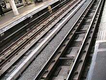
 traditional railway track (showing ballast, part of sleeper and fixing mechanisms)
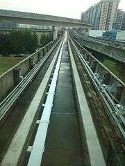 Track of Singapore LRT
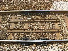
 Ballastless high-speed track in China
Ballastless track
A disadvantage of traditional track structures is the heavy demand for maintenance, particularly surfacing (tamping) and lining to restore the desired track geometry and smoothness of vehicle running. Weakness of the subgrade and drainage deficiencies also lead to heavy maintenance costs. This can be overcome by using ballastless track. In its simplest form this consists of a continuous slab of concrete (like a highway structure) with the rails supported directly on its upper surface (using a resilient pad).
There are a number of proprietary systems, and variations include a continuous reinforced concrete slab, or alternatively the use of pre-cast pre-stressed concrete units laid on a base layer. Many permutations of design have been put forward.
However, ballastless track has a high initial cost, and in the case of existing railroads the upgrade to such requires closure of the route for a long period. Its whole-life cost can be lower because of the reduction in maintenance. Ballastless track is usually considered for new very high speed or very high loading routes, in short extensions that require additional strength (e.g. railway stations), or for localised replacement where there are exceptional maintenance difficulties, for example in tunnels. Most rapid transit lines and rubber-tyred metro systems use ballastless track.[1]
Continuous longitudinally supported track
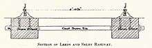
Early railways (c. 1840s) experimented with continuous bearing railtrack, in which the rail was supported along its length, with examples including Brunel's baulk road on the Great Western Railway, as well as use on the Newcastle and North Shields Railway,[2] on the Lancashire and Yorkshire Railway to a design by John Hawkshaw, and elsewhere.[3] Continuous-bearing designs were also promoted by other engineers.[4] The system was tested on the Baltimore and Ohio railway in the 1840s, but was found to be more expensive to maintain than rail with cross sleepers.[5]
This type of track still exists on some bridges on Network Rail where the timber baulks are called waybeams or longitudinal timbers. Generally the speed over such structures is low.[6]
Later applications of continuously supported track include Balfour Beatty's 'embedded slab track', which uses a rounded rectangular rail profile (BB14072) embedded in a slipformed (or pre-cast) concrete base (development 2000s).[7][8] The 'embedded rail structure', used in the Netherlands since 1976, initially used a conventional UIC 54 rail embedded in concrete, and later developed (late 1990s) to use a 'mushroom' shaped SA42 rail profile; a version for light rail using a rail supported in an asphalt concrete–filled steel trough has also been developed (2002).[9]
Modern ladder track can be considered a development of baulk road. Ladder track utilizes sleepers aligned along the same direction as the rails with rung-like gauge restraining cross members. Both ballasted and ballastless types exist.
Rail
Modern track typically uses hot-rolled steel with a profile of an asymmetrical rounded I-beam.[10] Unlike some other uses of iron and steel, railway rails are subject to very high stresses and have to be made of very high-quality steel alloy. It took many decades to improve the quality of the materials, including the change from iron to steel. The stronger the rails and the rest of the trackwork, the heavier and faster the trains the track can carry.
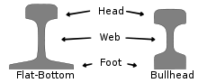
Other profiles of rail include: bullhead rail; grooved rail; "flat-bottomed rail" (Vignoles rail or flanged T-rail); bridge rail (inverted U–shaped used in baulk road); and Barlow rail (inverted V).
North American railroads until the mid- to late-20th century used rails 39 feet (12 m) long so they could be carried in gondola cars (open wagons), often 40 feet (12 m) long; as gondola sizes increased, so did rail lengths.
According to the Railway Gazette the planned-but-cancelled 150-kilometre rail line for the Baffinland Iron Mine, on Baffin Island, would have used older carbon steel alloys for its rails, instead of more modern, higher performance alloys, because modern alloy rails can become brittle at very low temperatures.[11]
Wooden rails
The earliest rails were made of wood, which wore out quickly. Hardwood such as jarrah and karri were better than softwoods such as fir. Longitudinal sleepers such as Brunel's baulk road are topped with iron or steel rails that are lighter than they might otherwise be because of the support of the sleepers.
Early North American railroads used iron on top of wooden rails as an economy measure but gave up this method of construction after the iron came loose, began to curl and went into the floors of the coaches. The iron strap rail coming through the floors of the coaches came to be referred to as "snake heads" by early railroaders.[12][13]
Rail classification (weight)
Rail is graded by weight over a standard length. Heavier rail can support greater axle loads and higher train speeds without sustaining damage than lighter rail, but at a greater cost. In North America and the United Kingdom, rail is graded by its linear density in pounds per yard (usually shown as pound or lb), so 130-pound rail would weigh 130 lb/yd (64 kg/m). The usual range is 115 to 141 lb/yd (57 to 70 kg/m). In Europe, rail is graded in kilograms per metre and the usual range is 40 to 60 kg/m (81 to 121 lb/yd). The heaviest rail mass-produced was 155 pounds per yard (77 kg/m) and was rolled for the Pennsylvania Railroad. The United Kingdom is in the process of transition from the imperial to metric rating of rail.[14]
Rail lengths
The rails used in rail transport are produced in sections of fixed length. Rail lengths are made as long as possible, as the joints between rails are a source of weakness. Throughout the history of rail production, lengths have increased as manufacturing processes have improved.
Timeline
The following are lengths of single sections produced by steel mills, without any thermite welding. Shorter rails may be welded with flashbutt welding, but the following rail lengths are unwelded.
- (1762)

- (1767)
- (1825)
- (1830)
- fish-belly rails at 35 lb/yd (17.4 kg/m), laid mostly on stone blocks.
- (1831)

- (1880)
- (1950)
- (1900)
- (1940s)
- (1953)
.svg.png)
Welding of rails into longer lengths was first introduced around 1893, making train rides quieter and safer. With the introduction of thermite welding after 1899, the process became less labor-intensive and ubiquitous.[20]
- (1895)

- (1899)
- (1904)
- (1935)
- (1950)
Modern production techniques allowed the production of longer unwelded segments.
- (2011)


- (2011)

- (2013)

Multiples
Newer longer rails tend to be made as simple multiples of older shorter rails, so that old rails can be replaced without cutting. Some cutting would be needed as slightly longer rails are needed on the outside of sharp curves compared to the rails on the inside.
Boltholes
Rails can be supplied pre-drilled with boltholes for fishplates or without where they will be welded into place. There are usually two or three boltholes at each end.
Joining rails
Rails are produced in fixed lengths and need to be joined end-to-end to make a continuous surface on which trains may run. The traditional method of joining the rails is to bolt them together using metal fishplates (jointbars in the US), producing jointed track. For more modern usage, particularly where higher speeds are required, the lengths of rail may be welded together to form continuous welded rail (CWR).
Jointed track
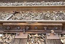
Jointed track is made using lengths of rail, usually around 20 m (66 ft) long (in the UK) and 39 or 78 ft (12 or 24 m) long (in North America), bolted together using perforated steel plates known as fishplates (UK) or joint bars (North America).
Fishplates are usually 600 mm (2 ft) long, used in pairs either side of the rail ends and bolted together (usually four, but sometimes six bolts per joint). The bolts have alternating orientations so that in the event of a derailment and a wheel flange striking the joint, only some of the bolts will be sheared, reducing the likelihood of the rails misaligning with each other and exacerbating the derailment. This technique is not applied universally; European practice being to have all the bolt heads on the same side of the rail.
Small gaps which function as expansion joints are deliberately left between the rail ends to allow for expansion of the rails in hot weather. European practice was to have the rail joints on both rails adjacent to each other, while North American practice is to stagger them. Because of these small gaps, when trains pass over jointed tracks they make a "clickety-clack" sound. Unless it is well-maintained, jointed track does not have the ride quality of welded rail and is less desirable for high speed trains. However, jointed track is still used in many countries on lower speed lines and sidings, and is used extensively in poorer countries due to the lower construction cost and the simpler equipment required for its installation and maintenance.
A major problem of jointed track is cracking around the bolt holes, which can lead to breaking of the rail head (the running surface). This was the cause of the Hither Green rail crash which caused British Railways to begin converting much of its track to continuous welded rail.
Insulated joints
Where track circuits exist for signalling purposes, insulated block joints are required. These compound the weaknesses of ordinary joints. Specially-made glued joints, where all the gaps are filled with epoxy resin, increase the strength again.
As an alternative to the insulated joint, audio frequency track circuits can be employed using a tuned loop formed in approximately 20 m (66 ft) of the rail as part of the blocking circuit. Some insulated joints are unavoidable within turnouts.
Another alternative is the axle counter, which can reduce the number of track circuits and thus the number of insulated rail joints required.
Continuous welded rail
Most modern railways use continuous welded rail (CWR), sometimes referred to as ribbon rails. In this form of track, the rails are welded together by utilising flash butt welding to form one continuous rail that may be several kilometres long. Because there are few joints, this form of track is very strong, gives a smooth ride, and needs less maintenance; trains can travel on it at higher speeds and with less friction. Welded rails are more expensive to lay than jointed tracks, but have much lower maintenance costs. The first welded track was used in Germany in 1924.[25] and has become common on main lines since the 1950s.
The preferred process of flash butt welding involves an automated track-laying machine running a strong electric current through the touching ends of two unjoined rails. The ends become white hot due to electrical resistance and are then pressed together forming a strong weld. Thermite welding is used to repair or splice together existing CWR segments. This is a manual process requiring a reaction crucible and form to contain the molten iron. Thermite-bonded joints are seen as less reliable and more prone to fracture or break.[26]
North American practice is to weld 1⁄4 mile (400 m) long segments of rail at a rail facility and load it on a special train to carry it to the job site. This train is designed to carry many segments of rail which are placed so they can slide off their racks to the rear of the train and be attached to the ties (sleepers) in a continuous operation.[27]
If not restrained, rails would lengthen in hot weather and shrink in cold weather. To provide this restraint, the rail is prevented from moving in relation to the sleeper by use of clips or anchors. Attention needs to be paid to compacting the ballast effectively, including under, between, and at the ends of the sleepers, to prevent the sleepers from moving. Anchors are more common for wooden sleepers, whereas most concrete or steel sleepers are fastened to the rail by special clips that resist longitudinal movement of the rail. There is no theoretical limit to how long a welded rail can be. However, if longitudinal and lateral restraint are insufficient, the track could become distorted in hot weather and cause a derailment. Distortion due to heat expansion is known in North America as sun kink, and elsewhere as buckling. In extreme hot weather special inspections are required to monitor sections of track known to be problematic. In North American practice extreme temperature conditions will trigger slow orders to allow for crews to react to buckling or "sun kinks" if encountered.[28]
After new segments of rail are laid, or defective rails replaced (welded-in), the rails can be artificially stressed if the temperature of the rail during laying is cooler than what is desired. The stressing process involves either heating the rails, causing them to expand,[29] or stretching the rails with hydraulic equipment. They are then fastened (clipped) to the sleepers in their expanded form. This process ensures that the rail will not expand much further in subsequent hot weather. In cold weather the rails try to contract, but because they are firmly fastened, cannot do so. In effect, stressed rails are a bit like a piece of stretched elastic firmly fastened down. In extremely cold weather, rails are heated to prevent "pull aparts".[30]
CWR is laid (including fastening) at a temperature roughly midway between the extremes experienced at that location. (This is known as the "rail neutral temperature".) This installation procedure is intended to prevent tracks from buckling in summer heat or pulling apart in the winter cold. In North America, because broken rails (known as a pull-apart) are typically detected by interruption of the current in the signaling system, they are seen as less of a potential hazard than undetected heat kinks.
Joints are used in the continuous welded rail when necessary, usually for signal circuit gaps. Instead of a joint that passes straight across the rail, the two rail ends are sometimes cut at an angle to give a smoother transition. In extreme cases, such as at the end of long bridges, a breather switch (referred to in North America and Britain as an expansion joint) gives a smooth path for the wheels while allowing the end of one rail to expand relative to the next rail.
Sleepers
A sleeper (tie) is a rectangular object on which the rails are supported and fixed. The sleeper has two main roles: to transfer the loads from the rails to the track ballast and the ground underneath, and to hold the rails to the correct width apart (to maintain the rail gauge). They are generally laid transversely to the rails.
Fixing rails to sleepers
Various methods exist for fixing the rail to the sleeper. Historically spikes gave way to cast iron chairs fixed to the sleeper, more recently springs (such as Pandrol clips) are used to fix the rail to the sleeper chair.
Portable track
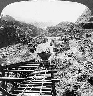
Sometimes rail tracks are designed to be portable and moved from one place to another as required. During construction of the Panama Canal, tracks were moved around excavation works. These track gauge were 5 ft (1,524 mm) and the rolling stock full size. Portable tracks have often been used in open pit mines. In 1880 in New York City, sections of heavy portable track (along with much other improvised technology) helped in the epic move of the ancient obelisk in Central Park to its final location from the dock where it was unloaded from the cargo ship SS Dessoug.
Cane railways often had permanent tracks for the main lines, with portable tracks serving the canefields themselves. These tracks were narrow gauge (for example, 2 ft (610 mm)) and the portable track came in straights, curves, and turnouts, rather like on a model railway.[31]
Decauville was a source of many portable light rail tracks, also used for military purposes.
The permanent way is so called because temporary way tracks were often used in the construction of that permanent way.
Layout
The geometry of the tracks is three-dimensional by nature, but the standards that express the speed limits and other regulations in the areas of track gauge, alignment, elevation, curvature and track surface are usually expressed in two separate layouts for horizontal and vertical.
Horizontal layout is the track layout on the horizontal plane. This involves the layout of three main track types: tangent track (straight line), curved track, and track transition curve (also called transition spiral or spiral) which connects between a tangent and a curved track.
Vertical layout is the track layout on the vertical plane including the concepts such as crosslevel, cant and gradient.[32][33]
A sidetrack is a railroad track other than siding that is auxiliary to the main track. The word is also used as a verb (without object) to refer to the movement of trains and railcars from the main track to a siding, and in common parlance to refer to giving in to distractions apart from a main subject.[34] Sidetracks are used by railroads to order and organize the flow of rail traffic.
Gauge
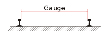
During the early days of rail, there was considerable variation in the gauge used by different systems. Today, 54.8% of the world's railways use a gauge of 1,435 mm (4 ft 8 1⁄2 in), known as standard or international gauge.[35][36] Gauges wider than standard gauge are called broad gauge; narrower, narrow gauge. Some stretches of track are dual gauge, with three (or sometimes four) parallel rails in place of the usual two, to allow trains of two different gauges to use the same track.[37]
Gauge can safely vary over a range. For example, U.S. federal safety standards allow standard gauge to vary from 4 ft 8 in (1,420 mm) to 4 ft 9 1⁄2 in (1,460 mm) for operation up to 60 mph (97 km/h).
Maintenance
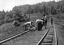
Track needs regular maintenance to remain in good order, especially when high-speed trains are involved. Inadequate maintenance may lead to a "slow order" (North American terminology, or Temporary speed restriction in the United Kingdom) being imposed to avoid accidents (see Slow zone). Track maintenance was at one time hard manual labour, requiring teams of labourers, or trackmen (US: gandy dancers; UK: platelayers; Australia: fettlers), who used lining bars to correct irregularities in horizontal alignment (line) of the track, and tamping and jacks to correct vertical irregularities (surface). Currently, maintenance is facilitated by a variety of specialised machines.

The surface of the head of each of the two rails can be maintained by using a railgrinder.
Common maintenance jobs include changing sleepers, lubricating and adjusting switches, tightening loose track components, and surfacing and lining track to keep straight sections straight and curves within maintenance limits. The process of sleeper and rail replacement can be automated by using a track renewal train.
Spraying ballast with herbicide to prevent weeds growing through and redistributing the ballast is typically done with a special weed killing train.
Over time, ballast is crushed or moved by the weight of trains passing over it, periodically requiring relevelling ("tamping") and eventually to be cleaned or replaced. If this is not done, the tracks may become uneven causing swaying, rough riding and possibly derailments. An alternative to tamping is to lift the rails and sleepers and reinsert the ballast beneath. For this, specialist "stoneblower" trains are used.
Rail inspections utilize nondestructive testing methods to detect internal flaws in the rails. This is done by using specially equipped HiRail trucks, inspection cars, or in some cases handheld inspection devices.
Rails must be replaced before the railhead profile wears to a degree that may trigger a derailment. Worn mainline rails usually have sufficient life remaining to be used on a branch line, siding or stub afterwards and are "cascaded" to those applications.
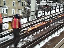
The environmental conditions along railroad track create a unique railway ecosystem. This is particularly so in the United Kingdom where steam locomotives are only used on special services and vegetation has not been trimmed back so thoroughly. This creates a fire risk in prolonged dry weather.
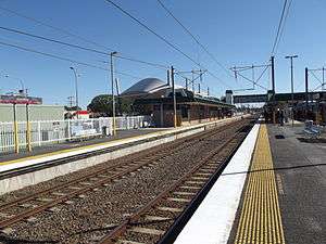
In the UK, the cess is used by track repair crews to walk to a work site, and as a safe place to stand when a train is passing. This helps when doing minor work, while needing to keep trains running, by not needing a Hi-railer or transport vehicle blocking the line to transport crew to get to the site.
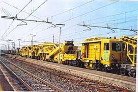 Maintenance of way equipment in Italy
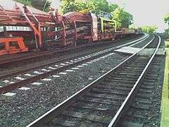
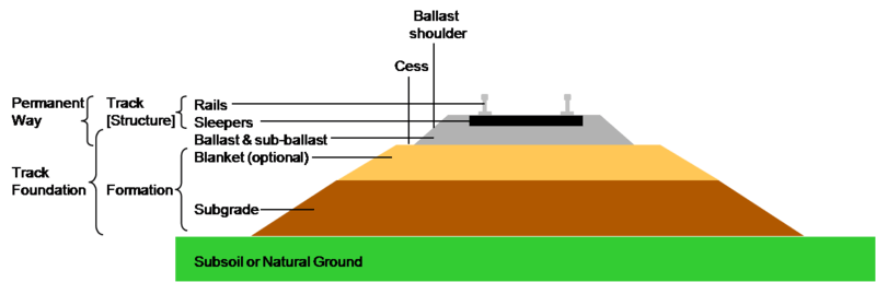
Bed and foundation
Railway tracks are generally laid on a bed of stone track ballast or track bed, which in turn is supported by prepared earthworks known as the track formation. The formation comprises the subgrade and a layer of sand or stone dust (often sandwiched in impervious plastic), known as the blanket, which restricts the upward migration of wet clay or silt. There may also be layers of waterproof fabric to prevent water penetrating to the subgrade. The track and ballast form the permanent way. The foundation may refer to the ballast and formation, i.e. all man-made structures below the tracks.
Some railroads are using asphalt pavement below the ballast in order to keep dirt and moisture from moving into the ballast and spoiling it. The fresh asphalt also serves to stabilize the ballast so it does not move around so easily.[38]
Additional measures are required where the track is laid over permafrost, such as on the Qingzang Railway in Tibet. For example, transverse pipes through the subgrade allow cold air to penetrate the formation and prevent that subgrade from melting.
The sub-grade layers are slightly sloped to one side to help drainage of water. Rubber sheets may be inserted to help drainage and also protect iron bridgework from being affected by rust.
Historical development
The technology of rail tracks developed over a long period, starting with primitive timber rails in mines in the 17th century.
See also
- Degree of curvature
- Difference between train and tram rails
- Exothermic welding
- Glossary of rail terminology
(including US/UK and other
regional/national differences) - Minimum railway curve radius
- Monorail
- Permanent way (history)
- Rack railway
- Rail profile
- Roll way, part of the track of a rubber-tyred metro[39]
- Rubber-tyred metro
- Street running
- Subgrade
- Tie plate
- TGV track construction
- Tramway (industrial)
- Tramway track
References
- Showing part of the track
- Morris, Ellwood (1841), "On Cast Iron Rails for Railways", American Railroad Journal and Mechanic's Magazine, 13 (7 new series): 270–277, 298–304
- Hawkshaw, J. (1849). "Description of the Permanent Way, of the Lancashire and Yorkshire, the Manchester and Southport, and the Sheffield, Barnsley and Wakefield Railways". Minutes of the Proceedings. 8 (1849): 261–262. doi:10.1680/imotp.1849.24189.
- Reynolds, J. (1838). "On the Principle and Construction of Railways of Continuous Bearing. (Including Plate)". ICE Transactions. 2: 73–86. doi:10.1680/itrcs.1838.24387.
- "Eleventh Annual Report (1848)", Annual report[s] of the Philadelphia, Wilmington and Baltimore Rail Road Company, 4, pp. 17–20, 1842
- "Waybeams at KEB, Newcastle, Network Rail Media Centre", Retrieved 21 January 2020
- 2.3.3 Design and Manufacture of Embedded Rail Slab Track Components (PDF), Innotrack, 12 June 2008
- "Putting slab track to the test", www.railwaygazette.com, 1 October 2002
- Esveld, Coenraad (2003), "Recent developments in slab track" (PDF), European Railway Review (2): 84–5
- A Metallurgical History of Railmaking Slee, David E. Australian Railway History, February, 2004 pp43-56
- Carolyn Fitzpatrick (24 July 2008). "Heavy haul in the high north". Railway Gazette. Archived from the original on 1 May 2009. Retrieved 10 August 2008.
Premium steel rails will not be used, because the material has an increased potential to fracture at very low temperatures. Regular carbon steel is preferred, with a very high premium on the cleanliness of the steel. For this project, a low-alloy rail with standard strength and a Brinell hardness in the range of 300 would be most appropriate.
- ""Snake heads" held up early traffic". Syracuse Herald-Journal. Syracuse, NY. 20 March 1939. p. 77 – via Newspapers.com.

- "Snakeheads on antebellum railroads". Frederick Jackson Turner Overdrive. 6 February 2012.
- "Metrication in other countries – US Metric Association". usma.org. Retrieved 1 October 2019.
- Reynolds
- Jessop and Outram
- "Big Weighing Machines". Australian Town and Country Journal (NSW : 1870 - 1907). NSW. 4 August 1900. p. 19. Retrieved 8 October 2011 – via National Library of Australia.
- McGonigal, Robert (1 May 2014). "Rail". ABC's of Railroading. Trains. Retrieved 10 September 2014.
- "Surveys Of New Rail Link". The Advertiser. Adelaide, SA. 17 June 1953. p. 5. Retrieved 3 October 2012 – via National Library of Australia.
- "Thermit®". Evonik Industries. Evonik Industries AG.
- "Opening Of S.-E. Broad Gauge line". The Advertiser. Adelaide, SA. 2 February 1950. p. 1. Retrieved 8 December 2011 – via National Library of Australia.
- "Ultra-long rails". voestalpine. voestalpine AG. Retrieved 10 September 2014.
- "Rails". Jindal Steel & Power Ltd. Retrieved 10 September 2014.
- "Tata Steel opens French plant to heat treat 108-meter train rail". International Organization on Shape Memory and Superelastic Technologies (SMST). ASM International. 30 October 2014. Retrieved 10 September 2014.
- C. P. Lonsdale (September 1999). "Thermite Rail Welding: History, Process Developments, Current Practices And Outlook For The 21st Century" (PDF). Proceedings of the AREMA 1999 Annual Conferences. The American Railway Engineering and Maintenance-of-Way Association. p. 2. Retrieved 6 July 2008.
- "Thermit Welding - an overview | ScienceDirect Topics". www.sciencedirect.com. Retrieved 1 October 2019.
- "Welded Rail Trains, CRHS Conrail Photo Archive". conrailphotos.thecrhs.org.
- Bruzek, Radim; Trosino, Michael; Kreisel, Leopold; Al-Nazer, Leith (2015). "Rail Temperature Approximation and Heat Slow Order Best Practices". 2015 Joint Rail Conference. pp. V001T04A002. doi:10.1115/JRC2015-5720. ISBN 978-0-7918-5645-1.
- "Continuous Welded Rail". Grandad Sez: Grandad's Railway Engineering Section. Archived from the original on 18 February 2006. Retrieved 12 June 2006.
- Holder, Sarah (30 January 2018). "In Case of Polar Vortex, Light Chicago's Train Tracks on Fire". CityLab. Atlantic Media. Retrieved 30 January 2019.
- Narrow Gauge Down Under magazine, January 2010, p. 20.
- PART 1025 Track Geometry (Issue 2 – 07/10/08 ed.). Department of Planning Transport, and Infrastructure - Government of South Australia. 2008.
- Track Standards Manual - Section 8: Track Geometry (PDF). Railtrack PLC. December 1998. Retrieved 13 November 2012.
- Dictionary.com
- "Dual gauge (1435mm-1520 mm) railway track on the Hungary-Ukraine border - Inventing Europe". www.inventingeurope.eu. Retrieved 1 October 2019.
- ChartsBin. "Railway Track Gauges by Country". ChartsBin. Retrieved 1 October 2019.
- "message in the mailing list '1520mm' on Р75 rails".
- "Hot Mix Asphalt Railway Trackbeds: Trackbed Materials, Performance Evaluations, and Significant Implications" (PDF). web.engr.uky.edu.
- runway (roll way)
Bibliography
- Pike, J., (2001), Track, Sutton Publishing, ISBN 0-7509-2692-9
- Firuziaan, M. and Estorff, O., (2002), Simulation of the Dynamic Behavior of Bedding-Foundation-Soil in the Time Domain, Springer Verlag.
- Robinson, A M (2009). Fatigue in railway infrastructure. Woodhead Publishing Limited. ISBN 978-1-85573-740-2.
- Lewis, R (2009). Wheel/rail interface handbook. Woodhead Publishing Limited. ISBN 978-1-84569-412-8.
External links
| Wikimedia Commons has media related to Rail tracks. |
- Table of North American tee rail (flat bottom) sections
- ThyssenKrupp handbook, Vignoles rail
- ThyssenKrupp handbook, Light Vignoles rail
- Track Details in photographs
- "Drawing of England Track Laying in Sections at 200 yards an hour" Popular Mechanics, December 1930
- Winchester, Clarence, ed. (1936), "The permanent way", Railway Wonders of the World, pp. 331–338 illustrated description of the construction and maintenance of the railway
- Railway technical