Scuba manifold
A scuba manifold is used to connect two diving cylinders containing breathing gas, providing a greater amount of gas for longer dive times or deeper dives. An isolation manifold allows the connection between the cylinders to be closed in the case of a leak from one of the cylinders or its valve or regulator, conserving the gas in the other cylinder. Diving with two or more cylinders is often associated with technical diving.
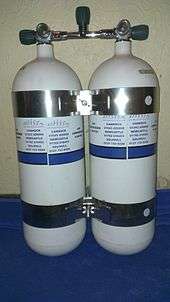
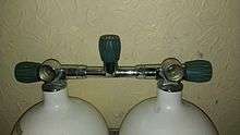 Two 300 bar scuba cylinders connected by an isolating manifold | |
| Uses | Connection between two scuba cylinders to link gas supply |
|---|---|

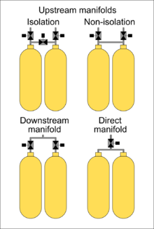
Several configurations are used, each with its own range of applications, advantages and disadvantages.
Function
Longer and deeper dives require a greater amount of breathing gas, in turn requiring higher filling pressure, a larger cylinder or multiple cylinders. A large diameter cylinder tends to move the diver's center of mass further from the centreline, making them unbalanced in the water, and a higher pressure cylinder has a similar effect, also reducing the buoyancy of the diver, due to the thicker metal required for strength.[1] Cylinder length is also limited by ergonomic considerations in proportion to the height of the diver. A single cylinder also presents a critical single point of failure for the breathing gas supply. Multiple-tank configurations include downstream manifolded twins, with a single regulator, independent or separate doubles which are two cylinders clamped to a backplate, but without a manifold, side mount cylinders, or upstream manifolded twins, with two complete regulator sets, which may have an isolation valve.[1][2][3]
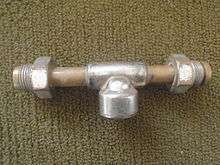
The function of a manifold is to connect the gas supplies of two back mounted cylinders (called doubles or twins), allowing the diver to breathe simultaneously from both. The manifold is a metal tube which is connected to the cylinder valves or directly to the cylinders, and may include an isolation valve or an outlet to connect a scuba regulator.[1]
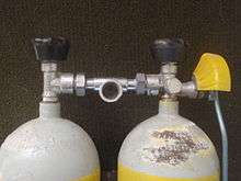
On an upstream manifold the left and right cylinder valves allow the corresponding first stage regulator to be shut off, leaving the entire gas supply to be used through the remaining regulator. On an isolation manifold, the central valve, called the isolating valve, separates the tanks into two independent systems, each with its own first-stage and second-stage regulators, which can prevent an upstream failure in one half of the system from losing the entire gas supply.[1]
History
Manifolded twin and triple cylinder sets have been used since the days of Cousteau and Gagnan's development of the open circuit regulator, as can be seen from early photographs of the equipment. These were downstream manifolds, which connected the cylinders together by linking the outlets of the cylinder valves, and had one outlet for a regulator. This arrangement allowed larger gas storage capacity using the limited range of cylinders available. Independent valving of the manifolded cylinders also allowed the gas supply to be monitored in the absence of submersible pressure gauges, by opening and closing the valves in a specific order, as the gas was used up. The need to remember the history of valve operation and the lack of facility to connect a redundant regulator made the use of independent twins the usual alternative. This also has limitations, even when the contents can be closely monitored by using submersible pressure gauges. In 1970 a group of divers including Tom Mount, Ike Ikehara and George Benjamin came up with the concept and had the first recorded dual outlet scuba valves prototyped. These allowed upstream connection of the cylinders, with a regulator on the valved outlet of each cylinder.[2]
Construction
The manifold is usually machined from a high grade brass alloy,[4] and chromium-plated for corrosion resistance and appearance. Brass is used because it is acceptably corrosion resistant, easy to machine, and suitable for oxygen service. The isolation valve uses similar materials, when present. Manifold lengths are available to connect different cylinder diameters, and centreline distance may be adjustable over a small range.
Upstream manifolds
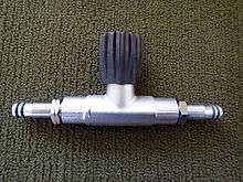
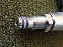
Manifolds intended for use with sets where a regulator is provided for each cylinder are connected to the cylinder valves upstream of the cylinder valve seat, to a connecting port provided specifically for this purpose. Two styles of connection are available for this arrangement – face seal, and barrel seal. Face seal connections are similar to the DIN regulator connection seal, and consist of an o-ring in a groove machined into the end of the manifold tube, which is clamped against the face of the valve port by a threaded component. Face seals are simple and rugged, but rely on tight connection for a reliable seal, and do not allow any adjustment for cylinder centre distance. Barrel seals use one or two O-rings in grooves around the end of the manifold tube, which seal against the bore of the valve port. They are usually screwed into the valve port with handed thread, and locked with a lock-nut. They are generally slightly less rugged than face seal manifolds, and more vulnerable to thread damage during assembly, but allow a small amount of cylinder centre distance adjustment, and provide a reliable seal even if not completely tight. Manifolds of this type are commonly supplied in sets comprising a manifold and compatible left and right side cylinder valves with a choice of neck thread specification. The working components for all three valves in the set are usually identical.
Downstream manifolds
Earlier manifolds were used to connect cylinders together downstream of the cylinder valve, using the DIN or yoke fittings on standard cylinder valves. These manifolds do not generally include an isolation valve, as the cylinder valves can be used to isolate the cylinders. However, they also do not provide for more than one regulator. Some of these earlier manifolds included a reserve valve at the connection point for the regulator.
Direct manifolds
A third style of manifold screwed directly into the cylinder neck thread, and provided a single valve which controlled flow from both cylinders to a single connector for a regulator. These manifolds could also include a reserve valve. From a gas management point of view they are identical to a single cylinder with the same capacity.
Advantages
Compared to a single cylinder of equivalent capacity:
- Ergonomic – Provides a more comfortable fit of cylinders with a lower profile and centre of mass closer to the diver's centreline, for better balance in the water.
Compared to independent twins:
- Operational simplicity – the ability to breathe through an entire dive from a single regulator without the need to change second stages, except in an emergency or to change gases for decompression.
- Only one submersible pressure gauge is necessary if the isolation valve is normally open.
Isolation manifold compared to plain manifold:
- Standard malfunction management – in case of a regulator or manifold malfunction a standard procedure can be used to limit the gas loss. The diver can localize the malfunction and isolate it from the functioning system by closing the necessary valves.[1]
Disadvantages
Compared to independent twins:
- A manifold is a single point of failure for the gas supply, especially dangerous in overhead environments such as caves or wrecks. An isolating manifold localises the single point of failure to the isolating valve itself.
- An upstream manifolded set must be emptied to split if needed as singles.
Compared to a single large cylinder:
- The manifold, valves and second cylinder are an additional cost, both for capital outlay and maintenance.
- The twin set is usually heavier than the equivalent single.
Compared to side-mount:
- The manifold and valves are vulnerable to damage by impact with the overhead, and to snagging.
- The valves are difficult to reach for many divers, reducing the effectiveness of isolation procedures.
Management of the manifold in gas supply emergencies
Regulator malfunction
If a regulator malfunctions on a set with an upstream manifold, the diver closes the relevant cylinder valve and switches to the other regulator. The entire remaining gas supply is available for the rest of the dive.[1]
Cylinder connection leak
Cylinder to manifold connection malfunction, though rare, can result in an extremely violent gas loss. On a set with an isolation manifold, the diver closes the isolating valve to preserve the gas in the cylinder which is not leaking, then uses the leaking cylinder while gas remains, and switches to the intact side cylinder when the leaky one is empty. At least half of the remaining gas volume is available for the remainder of the dive. If there is no isolation valve the entire gas supply may be lost.[1]
See also
- Diving cylinder – High pressure compressed gas cylinder used to store and supply breathing gas for diving
- Doing It Right (scuba diving) – Technical diving safety philosophy
- manifold (fluid mechanics) – Structure that splits or combines fluid flow into channels
References
- Beresford, Michael (2006). CMAS-ISA Advanced Nitrox Diver Manual (3rd ed.). CMAS-ISA.
- Mount, Tom (August 2008). "9: Equipment Configuration". In Mount, Tom; Dituri, Joseph (eds.). Exploration and Mixed Gas Diving Encyclopedia (1st ed.). Miami Shores, Florida: International Association of Nitrox Divers. p. 95. ISBN 978-0-915539-10-9.
- Roberts, Fred M. (1963). Basic Scuba: Self contained underwater breathing apparatus: Its operation, maintenance and use (2nd ed.). New York: Van Nostrand Reinholdt.
- "OMS SCUBA Valves & Manifolds". OMS. 2013. Retrieved 6 May 2013.