Mechanism of diving regulators
The mechanism of diving regulators is the arrangement of components and function of gas pressure regulators used in the systems which supply breathing gases for underwater diving. Both free-flow and demand regulators use mechanical feedback of the downstream pressure to control the opening of a valve which controls gas flow from the upstream, high-pressure side, to the downstream, low-pressure side of each stage.[1] Flow capacity must be sufficient to allow the downstream pressure to be maintained at maximum demand, and sensitivity must be appropriate to deliver maximum required flow rate with a small variation in downstream pressure, and for a large variation in supply pressure, without instability of flow. Open circuit scuba regulators must also deliver against a variable ambient pressure. They must be robust and reliable, as they are life-support equipment which must function in the relatively hostile seawater environment, and the human interface must be comfortable over periods of several hours.
Diving regulators use mechanically operated valves.[1] In most cases there is ambient pressure feedback to both first and second stage, except where this is avoided to allow constant mass flow through an orifice in a rebreather, which requires a constant absolute upstream pressure. Back-pressure regulators are used in gas reclaim systems to conserve expensive helium based breathing gases in surface-supplied diving, and to control the safe exhaust of exhaled gas from built-in breathing systems in hyperbaric chambers.
The parts of a regulator are described here as the major functional groups in downstream order as following the gas flow from the cylinder to its final use. Details may vary considerably between manufacturers and models.
Types of diving regulator
Gas pressure regulators are used for several applications in the supply and handling of breathing gases for diving. Pressure reducing regulators are used to reduce gas pressure for supply to the diver in demand and free-flow open circuit breathing apparatus, in rebreather equipment, and in gas blending procedures. Back-pressure regulators are used in the exhaust systems of the built-in breathing systems of diving chambers, and in the recovery of used helium based breathing gas for recycling. Some of these regulators must work underwater, others in the more forgiving conditions of the surface support area. All must work consistently and reliably, but some are parts of safety-critical life-support systems, where a single point of failure must not put lives at risk.
Open-circuit scuba regulators
Connection to the high pressure supply
.jpg)
The first-stage of the scuba regulator may be connected to the cylinder valve by one of two standard types of fittings. The CGA 850 connector, also known as an international connector, which uses a yoke clamp, or a DIN screw fitting to connect it to the valve of the diving cylinder. There are also European standards for scuba regulator connectors for gases other than air.
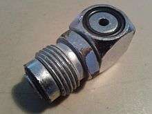
CGA 850 connection
CGA 850 Yoke connectors (sometimes called A-clamps from their shape) are the most popular regulator connection in North America and several other countries. They clamp the high pressure inlet opening of the regulator against the outlet opening of the cylinder valve, and are sealed by an O-ring in a groove in the contact face of the cylinder valve. The user screws the clamp in place finger-tight to hold the metal surfaces of cylinder valve and regulator first stage in contact, compressing the o-ring between the radial faces of valve and regulator. When the valve is opened, gas pressure presses the O-ring against the outer cylindrical surface of the groove, completing the seal. The diver must take care not to screw the yoke down too tightly, or it may prove impossible to remove without tools. Conversely, failing to tighten sufficiently can lead to O-ring extrusion under pressure and a major loss of breathing gas. This can be a serious problem if it happens when the diver is at depth. Yoke fittings are rated up to a maximum of 240 bar working pressure.
The outlet of the CGA 850 valve is on a flat surface on the valve body, inside a concentric face-sealing O-ring groove, with a conical indentation on the opposite surface of the valve body, co-axial with the O-ring groove. The yoke clamp fits around the valve body and the sealing face of the regulator inlet seats over the O-ring groove. A conically tipped screw locates in the indentation and when tightened, presses against the valve body and pulls the sealing face of the regulator inlet against the O-ring. This screw must be tightened sufficiently to maintain metal-to-metal contact between the regulator inlet and the valve body when the valve is opened at full cylinder pressure, and under normal working loads including minor impacts and using the regulator as a handle to lift the set, to prevent failure of the seal by O-ring extrusion and consequent loss of breathing gas. The screw must also not be over-tightened, as after use it must be removed by hand. The rigidity of the yoke varies depending on design, tightening is by hand and is left to the discretion of the user. Fortunately the mechanism is fairly tolerant of variation in contact force. When the valve is opened, gas pressure on the O-ring presses it against the outer cylindrical surface of the groove and the face of the regulator inlet, squeezing the O-ring towards the contact surfaces of these parts. The pressure exerts a force to push the regulator away from the valve body, and if pre-load of the screw is insufficient the elasticity of the clamp will allow a gap to form between valve and regulator through which the O-ring may be extruded. When this happens, gas loss is rapid, and the valve must be closed and the clamp loosened, the O-ring inspected and possibly replaced. Recovery from an extruded O-ring underwater is often not possible and bailout to an independent gas supply or an emergency ascent may be necessary.
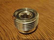
DIN connection
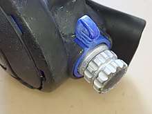
The DIN fitting is a type of screw-in connection to the cylinder valve. The DIN system is less common worldwide, but has the advantage of withstanding greater pressure, up to 300 bar, allowing use of high-pressure steel cylinders. They are less susceptible to blowing the O-ring seal if banged against something while in use. DIN fittings are the standard in much of Europe and are available in most countries. The DIN fitting is considered more secure and therefore safer by many technical divers.[2]:117
DIN valves are produced in 232 bar and 300 bar pressure ratings. The number of threads and the detail configuration of the connections is designed to prevent incompatible combinations of filler attachment or regulator attachment with the cylinder valve.[3]
- 232 bar DIN (5-thread, G5/8) Outlet/Connector #13 to DIN 477 part 1.[3]
- 300 bar DIN (7-thread, G5/8) Outlet/Connector #56 to DIN 477 part 5 - these are similar to 5-thread DIN fitting but are rated to 300 bar working pressures.[3] The 300 bar pressures are common in European diving and in US cave diving.
Adapters
.jpg)

Adapters are available enabling a DIN first-stage to be attached to a cylinder with a yoke fitting valve (yoke adapter or A-clamp adapter), and for a yoke first stage to be attached to a DIN cylinder valve (plug adapter and block adapter).[2]:118
Other connection types
There are also cylinder valves intended for scuba cylinders containing gases other than air:
- The European Norm EN 144-3:2003 introduced a new type of valve, similar to existing 232 bar or 300 bar DIN valves, but with a metric M26×2 thread. These are intended to be used for breathing gas with oxygen content above that normally found in natural air in the Earth's atmosphere (i.e. 22–100%).[4] From August 2008, these were required in the European Union for all diving equipment used with nitrox or pure oxygen. The idea behind this new standard is to prevent a rich mixture being filled to a cylinder that is not oxygen clean. However even with use of the new system there still remains nothing except human procedural care to ensure that a cylinder with a new valve remains oxygen-clean[4] - which is exactly how the previous system worked.
- An M 24x2 male thread cylinder valve was supplied with some Dräger semi-closed circuit recreational rebreathers (Dräger Ray) for use with nitrox mixtures.[5] The regulator supplied with the rebreather had a compatible connection.
Cylinder valve types
Most scuba cylinder valves are currently of the K-valve type, which is a simple manually operated screw-down on-off valve. In the mid-1960s, J-valves were widespread. J-valves contain a spring-operated valve that restricts or shuts off flow when tank pressure falls to 300-500 psi, causing breathing resistance and warning the diver that he or she is dangerously low on air. The reserve air is released by pulling a reserve lever on the valve. J-valves fell out of favor with the introduction of pressure gauges, which allow divers to keep track of their air underwater, especially as the valve-type is vulnerable to accidental release of reserve air and increases the cost and servicing of the valve. J-valves are occasionally still used when work is done in visibility so poor that the pressure gauge cannot be seen, even with a light.[2]:167–178:Sec 7.2.2 Most side-spindled valves are right handed, meaning that the knob is on the diver's right hand side, but left handed valves are also produced for manifolded sets and other applications where it is more convenient. Axial spindle valves are also available where the spindle lies on the axis of the thread which connects the valve to the cylinder, with the knob on top.
Single-hose demand regulators

Most contemporary diving regulators are single-hose two-stage demand regulators. They consist of a first-stage regulator, and a second-stage demand valve. A low pressure hose connects these components to transfer breathing gas, and allows relative movement within the constraints of hose length and flexibility. Other low pressure hoses supply optional additional components.
First stage
The first stage of the regulator is mounted to the cylinder valve or manifold via one of the standard connectors (Yoke or DIN). It reduces cylinder pressure to an intermediate pressure, usually about 8 to 11 bars (120 to 160 psi) higher than the ambient pressure, also called interstage pressure, medium pressure or low pressure. The breathing gas is then supplied to the second stage through a hose.[1]:17–20
A balanced regulator first stage automatically keeps a constant pressure difference between the interstage pressure and the ambient pressure even as the tank pressure drops with consumption. The balanced regulator design allows the first stage orifice to be as large as needed without incurring performance degradation as a result of changing tank pressure.[1]:17–20
The first stage regulator body generally has several low-pressure outlets (ports) for second-stage regulators, BCD inflators and other equipment; and one or more high-pressure outlets, which allow a submersible pressure gauge (SPG) or gas-integrated diving computer to read the cylinder pressure. The valve may be designed so that one low-pressure port is designated "Reg" for the primary second stage regulator, because that port allows a higher flow rate to give less breathing effort at maximum demand. A small number of manufacturers have produced regulators with a larger than standard hose and port diameter for this primary outlet.[7]:50
The mechanism inside the first stage can be of the diaphragm type or the piston type. Both types can be balanced or unbalanced. Unbalanced regulators have the cylinder pressure pushing the first stage upstream valve closed, which is opposed by the intermediate stage pressure and a spring. As cylinder pressure falls the closing force is less, so the regulated pressure increases at lower tank pressure. To keep this pressure rise within acceptable limits the high-pressure orifice size is limited, but this decreases the total flow capacity of the regulator. A balanced regulator keeps about the same ease of breathing at all depths and pressures, by using the cylinder pressure to also indirectly oppose the opening of the first stage valve.[1]:17–20
Piston-type first stage
Some components of piston-type first stages are easier to manufacture and have a simpler design than the diaphragm type. They may need more careful maintenance because some internal moving parts may be exposed to water and any contaminants in the water.[1]:9–13
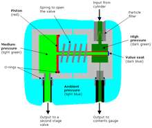
The piston in the first stage is rigid and acts directly on the seat of the valve. The pressure in the intermediate pressure chamber drops when the diver inhales from the demand valve, this causes the piston to lift off the stationary valve seat as the piston slides into the intermediate pressure chamber. The now open valve permits high pressure gas to flow into the low pressure chamber until the pressure in the chamber has risen enough to push the piston back into its original position against the seat and thus close the valve.[1]:9–13
Diaphragm-type first stage


Diaphragm-type first stages are more complex and have more components than the piston type. Their design makes them particularly suited to cold water diving and to working in saltwater and water containing a high degree of suspended particles, silt, or other contaminating materials, since the only moving parts exposed to the water are the valve opening spring and the diaphragm, all other parts are sealed off from the environment. In some cases the diaphragm and spring are also sealed from the environment.[8][1]:9–13
The diaphragm is a flexible cover to the medium (intermediate) pressure chamber. When the diver consumes gas from the second stage, the pressure falls in the low pressure chamber and the diaphragm deforms inwards pushing against the valve lifter. This opens the high pressure valve permitting gas to flow past the valve seat into the low pressure chamber. When the diver stops inhaling, pressure in the low pressure chambers rises and the diaphragm returns to its neutral flat position and no longer presses on the valve lifter shutting off the flow until the next breath is taken.[1]:9–13
Balancing
If a regulator stage has an architecture that compensates for a change of upstream pressure on the moving parts of the valve so that a change in supply pressure does not affect the force required to open the valve, the stage is described as balanced. Upstream and downstream valves, first and second stages, and diaphragm and piston operation can be balanced or unbalanced, and a full description of a stage will specify which of all of these options apply. For example, a regulator may have a balanced piston first stage with a balanced downstream second stage. Both balanced and unbalanced piston first stages are fairly common, but most diaphragm first stages are balanced. Balancing the first stage has a greater overall effect on the performance of a regulator, as the variation in supply pressure from the cylinder is much greater than the variation in interstage pressure, even with an unbalanced first stage. However the second stage operates on very a small pressure differential and is more sensitive to variations in supply pressure. Most top range regulators have at least one balanced stage, but it is not clear that balancing both stages makes a noticeable difference to performance.[1]:17–20
Interstage hose
An intermediate-pressure, medium pressure, or low pressure hose, is used to carry breathing gas (typically at between 8 and 10 bar above ambient) from the first stage regulator to the second stage, or demand valve, which is held in the mouth by the diver, or attached to the full face mask or diving helmet.[2]:88 The standard interstage hose is 30 inches (76 cm) long, but 40 inches (100 cm) hoses are standard for Octopus regulators and 7 feet (2.1 m) hoses are popular for technical diving, particularly for cave and wreck penetration where space constraints may make it necessary to swim in single file while sharing gas. Other lengths are also available. Most low pressure ports are threaded 3/8" UNF, but a few regulators were marketed with one 1/2" UNF port intended for the primary demand valve. High pressure ports are almost exclusively 7/16" UNF. There is no possibility of connecting a hose to the wrong pressure port.[2]:112
Second-stage

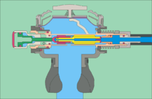
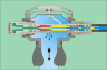
The second stage, or demand valve reduces the pressure of the interstage air supply to ambient pressure on demand from the diver. The operation of the valve is triggered by a drop in downstream pressure as the diver breathes in.
Upstream valves
In an upstream valve, the moving part works against the pressure and opens in the opposite direction to the flow of gas. They are often made as tilt-valves, which are mechanically extremely simple and reliable, but are not amenable to fine tuning.[2]:14
If the first stage leaks and the inter-stage over-pressurizes, the second stage downstream valve opens automatically resulting in a "freeflow". With an upstream valve, the result of over-pressurization may be a blocked valve. This will stop the supply of breathing gas and possibly result in a ruptured hose or the failure of another second stage valve, such as one that inflates a buoyancy device. When a second stage upstream tilt valve is used a relief valve should be included by the manufacturer on the first stage regulator to protect the intermediate hose.[2]:9
If a shut-off valve is fitted between the first and second stages, as is found on scuba bailout systems used for commercial diving and in some technical diving configurations, the demand valve will normally be isolated and unable to function as a relief valve. In this case an overpressure valve must be fitted to the first stage if it does not already have one. As very few contemporary (2016) scuba regulator first stages are factory fitted with overpressure relief valves, they are available as aftermarket accessories which can be screwed into any low pressure port available on the first stage.[9]
Downstream valves
Most modern demand valves use a downstream rather than an upstream valve mechanism. In a downstream valve, the moving part of the valve opens in the same direction as the flow of gas and is kept closed by a spring. The usual form of downstream valve is a spring-loaded poppet with a hard elastomer seat sealing against an adjustable metal "crown" around the inlet orifice. The poppet is lifted away from the crown by a lever operated by the diaphragm.[2]:13–15 Two patterns are commonly used. One is the classic push-pull arrangement, where the actuating lever goes onto the end of the valve shaft and is held on by a nut. Any deflection of the lever is converted to an axial pull on the valve shaft, lifting the seat off the crown and allowing air to flow.[2]:13 The other is the barrel poppet arrangement, where the poppet is enclosed in a tube which crosses the regulator body and the lever operates through slots in the sides of the tube. The far end of the tube is accessible from the side of the casing and a spring tension adjustment screw may be fitted for limited diver control of the cracking pressure. This arrangement also allows relatively simple pressure balancing of the second stage.[2]:14,18
A downstream valve will function as an over-pressure valve when the inter-stage pressure is raised sufficiently to overcome the spring pre-load. If the first stage leaks and the inter-stage over-pressurizes, the second stage downstream valve opens automatically. if the leak is bad this could result in a "freeflow", but a slow leak will generally cause intermittent "popping" of the DV, as the pressure is released and slowly builds up again.[2]:
Servo-controlled valves
Some demand valves use a small, sensitive pilot valve to control the opening of the main valve. The Poseidon Jetstream and Xstream and Oceanic Omega second stages are examples of this technology. They can produce very high flow rates for a small pressure differential, and particularly for a relatively small cracking pressure. They are generally more complicated and expensive to service.[2]:16
Exhaust valves

Exhaust valves are necessary to prevent the diver inhaling water, and to allow a negative pressure difference to be induced over the diaphragm to control the demand valve. The exhaust valves should operate at a very small pressure difference, and cause as little resistance to flow as reasonably possible, without being cumbersome and bulky. Elastomer mushroom valves serve the purpose adequately,[2]:108 though duckbill valves were also common in twin-hose regulators. Where it is important to avoid leaks back into the regulator, such as when diving in contaminated water, a system of two sets of valves in series can reduce the risk of contamination. A more complex option which can be used for surface supplied helmets, is to use a reclaim exhaust system which uses a separate flow regulator to control the exhaust which is returned to the surface in a dedicated hose in the umbilical.[10]:109
Exhaust manifold

The exhaust manifold (exhaust tee, exhaust cover, whiskers) is the ducting that protects the exhaust valve(s) and diverts the exhaled air to the sides so that it does not bubble up in the diver's face and obscure the view. This is not necessary for twin hose regulators as they exhaust air behind the shoulders.[2]:33
Purge button
A standard fitting on single-hose second stages, both mouth-held and built into a full-face mask or demand helmet, is the purge-button, which allows the diver to manually deflect the diaphragm to open the valve and cause air to flow into the casing. This is usually used to purge the casing or full-face mask of water if it has flooded. This will often happen if the second stage is dropped or removed from the mouth while under-water.[2]:108 It is either a separate part mounted in the front cover or the cover may be made flexible and serves as the purge button. Depressing the purge button presses against the diapragm directly over the lever of the demand valve, and this movement of the lever opens the valve to release air through the regulator.[11] The tongue may be used to block the mouthpiece during purging to prevent water or other matter in the regulator from being blown into the diver's airway by the air blast. This is particularly important when purging after vomiting through the regulator.
The purge button is also used by recreational divers to inflate a delayed surface marker buoy or lifting bag. Any time that the purge button is operated, the diver must be aware of the potential for a freeflow and be ready to deal with it.[12]
User adjustable flow modifiers
It may be desirable for the diver to have some control over the flow characteristics of the demand valve. The usual adjustable aspects are cracking pressure and the feedback from flow rate to internal pressure of the second stage housing. The inter-stage pressure of surface supplied demand breathing apparatus is controlled manually at the control panel, and does not automatically adjust to the ambient pressure in the way that most scuba first stages do, as this feature is controlled by feedback to the first stage from ambient pressure. This has the effect that the cracking pressure of a surface supplied demand valve will vary slightly with depth, so some manufacturers provide a manual adjustment knob on the side of the demand valve housing to adjust spring pressure on the downstream valve, which controls the cracking pressure. The knob is known to commercial divers as "dial-a-breath". A similar adjustment is provided on some high-end scuba demand valves, to allow the user to manually tune the breathing effort at depth[2]:17
Scuba demand valves which are set to breathe lightly (low cracking pressure, and low work of breathing) may tend to free-flow relatively easily, particularly if the gas flow in the housing has been designed to assist in holding the valve open by reducing the internal pressure. The cracking pressure of a sensitive demand valve is often less than the hydrostatic pressure difference between the inside of an air-filled housing and the water below the diaphragm when the mouthpiece is pointed upwards. To avoid excessive loss of gas due to inadvertent activation of the valve when the DV is out of the diver's mouth, some second stages have a desensitising mechanism which causes some back-pressure in the housing, by impeding the flow or directing it against the inside of the diaphragm.[2]:21
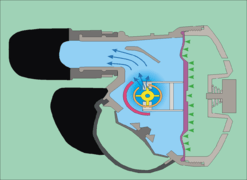 Inhalation flow with venturi assist activated
 Inhalation flow with venturi assist de-activated
Twin-hose demand regulators

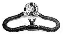

The "twin", "double" or "two" hose configuration of scuba demand valve was the first in general use.[13] This type of regulator has two large bore corrugated breathing tubes. One tube is to supply air from the regulator to the mouthpiece, and the second tube delivers the exhaled gas to a point where the ambient pressure is identical to the demand diaphragm, where it is released through a rubber duck-bill one-way valve, and comes out of the holes in the cover. Advantages of this type of regulator are that the bubbles leave the regulator behind the diver's head, increasing visibility, reducing noise and producing less load on the diver's mouth, They remain popular with some underwater photographers and Aqualung brought out an updated version of the Mistral in 2005.[14][15]
In Cousteau's original aqualung prototype, there was no exhaust hose, and the exhaled air exited through a one-way valve at the mouthpiece. It worked out of water, but when he tested the aqualung in the river Marne air free-flowed from the regulator before it could be breathed when the mouthpiece was above the regulator. After that, he had the second breathing tube fitted. Even with both tubes fitted, raising the mouthpiece above the regulator increases the delivered pressure of gas and lowering the mouthpiece reduces delivered pressure and increases breathing resistance. As a result, many aqualung divers, when they were snorkeling on the surface to save air while reaching the dive site, put the loop of hoses under an arm to avoid the mouthpiece floating up causing free flow.
Ideally the delivered pressure is equal to the resting pressure in the diver's lungs as this is what human lungs are adapted to breathe. With a twin hose regulator behind the diver at shoulder level, the delivered pressure changes with diver orientation. if the diver rolls on his or her back the released air pressure is higher than in the lungs. Divers learned to restrict flow by using their tongue to close the mouthpiece. When the cylinder pressure was running low and air demand effort rising, a roll to the right side made breathing easier. The mouthpiece can be purged by lifting it above the regulator(shallower), which will cause a free flow.[16]:341
Twin hose regulators have been superseded almost completely by single hose regulators and became obsolete for most diving since the 1980s.[17]
The original twin-hose regulators usually had no ports for accessories, though some had a high pressure port for a submersible pressure gauge. Some later models have one or more low-pressure ports between the stages, which can be used to supply direct feeds for suit or BC inflation and/or a secondary single hose demand valve, and a high pressure port for a submersible pressure gauge.[16] The new Mistral is an exception as it is based on the Aqualung Titan first stage. which has the usual set of ports.[14]
The twin-hose arrangement with a mouthpiece or full-face mask is common in rebreathers, but as part of the breathing loop, not as part of a regulator. The associated demand valve comprising the bail-out valve is a single hose regulator.
The mechanism of the twin hose regulator is packaged in a usually circular metal housing mounted on the cylinder valve behind the diver's neck. The demand valve component of a two-stage twin hose regulator is thus mounted in the same housing as the first stage regulator, and in order to prevent free-flow, the exhaust valve must be located at the same depth as the diaphragm, and the only reliable place to do this is in the same housing. The air flows through a pair of corrugated rubber hoses to and from the mouthpiece. The supply hose is connected to one side of the regulator body and supplies air to the mouthpiece through a non-return valve, and the exhaled air is returned to the regulator housing on the outside of the diaphragm, also through a non-return valve on the other side of the mouthpiece and usually through another non-return exhaust valve in the regulator housing - often a "duckbill" type.[16]
A non-return valve is usually fitted to the breathing hoses where they connect to the mouthpiece. This prevents any water that gets into the mouthpiece from going into the inhalation hose, and ensures that once it is blown into the exhalation hose that it cannot flow back. This slightly increases the flow resistance of air, but makes the regulator easier to clear.[16]:341
Some early twin hose regulators were of single-stage design. The first stage functions in a way similar to the second stage of two-stage demand valves, but would be connected directly to the cylinder valve and reduced high pressure air from the cylinder directly to ambient pressure on demand. This could be done by using a longer lever and larger diameter diaphragm to control the valve movement, but there was a tendency for cracking pressure, and thus work of breathing, to vary as the cylinder pressure dropped.[16]
Constant mass flow regulators
Constant mass flow semi-closed circuit diving rebreathers need a gas supply that has a constant pressure to feed the sonic orifice. These are generally slightly modified open circuit scuba first stages with the ambient pressure input blanked off. Connection to the high pressure cylinder is the same as for open-circuit scuba, as the cylinders and valves are also for underwater service,
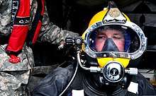
Surface supply regulators
The regulators used for providing surface-supplied breathing gases from high pressure storage systems to the gas panel for diving are normal industrial pressure reduction regulators capable of providing the necessary flow rate. Connection to the high-pressure cylinders follows the national practice for industrial high-pressure gas systems for the relevant gases.
Surface-supplied breathing gas may be supplied to a free-flow helmet or a demand supplied helmet, and the gas nay be either discharged to the environment at ambient pressure or returned to the surface for recycling if this is economically desirable. Free-flow systems require a relatively high flow rate as the gas is continuously supplied to the helmet, and the diver breathes from it as it passes through. Flow rate must be sufficient to prevent rebreathing of exhaled gas from the dead space of the helmet, and must allow for maximum inspired flow rate at depth. Flow rate of a demand helmet must also allow for maximum inspired flow rate, but this only occurs intermittently during the breathing cycle, and average flow is much less. The regulator must be capable of the same maximum flow rate, but cooling effects are much less for demand service.
The demand valves used on surface-supplied diving helmets and full-face masks work on exactly the same principles as the second stage scuba demand valves of single hose scuba, and in some cases may be the same unit with a different housing compatible with the specific mask or helmet. The demand valves used with surface supplied gas will normally have a supply that is not consistently at the same pressure above ambient pressure, so usually have a cracking pressure adjustment knob, known in the industry as "dial a breath". The breathing gas is delivered from the surface or bell gas panel via a breathing gas supply hose in the diver's umbilical, which commonly uses a JIC-6 or 9/16 UNF fitting at the diver’s end of the hose, which is usually 3/8" bore.[18]
A very similar application is the regulation of gas pressure from the on-board emergency gas high-pressure storage cylinders of an open or closed diving bell. The regulator in these cases must be accessible to the bellman, so it is generally mounted at the bell gas panel. In this application the regulator is exposed to the same ambient pressure as the divers in the bell. Pressure from the on-board gas is typically kept just below surface supply pressure, so that it will automatically cut in if the surface supply pressure fails.[19]
Reclaim regulators
Reclaim helmets use a surface supply system to provide breathing gas to the diver in the same way as in the open circuit helmets, but also have a return system to reclaim and recycle the exhaled gas to save the expensive helium diluent, which would be discharged to the surrounding water and lost in an open circuit system. The reclaimed gas is returned to the surface through a hose in the umbilical which is provided for this purpose, passed through a scrubber to remove carbon dioxide, and can then be repressurised and blended with oxygen to the required mix before storage for later use.[20][21]
In order to allow the exhaust gas to be discharged from the helmet safely, it must pass through an exhaust regulator, which works on the principle of a back-pressure regulator, activated by the pressure difference between the interior of the helmet and the ambient pressure. The reclaim exhaust valve may be a two-stage valve for lower resistance, and will generally have a manual bypass valve which allows exhaust to the ambient water. The helmet will have an emergency flood valve to prevent possible exhaust regulator failure from causing a helmet squeeze before the diver can bypass it manually.[22]
Reclaim gas flow to the topside processing system will generally pass through a back-pressure regulator in the bell, and another at the intake to the processing system. These ensure that the line pressure in the reclaim hose is at approximately 1 bar below ambient at the diver, and 2 bar below diver ambient in the bell umbilical.[20]
Built-in breathing system regulators
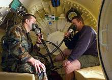

A built-in breathing system is a source of breathing gas installed in a confined space where an alternative to the ambient gas may be required for medical treatment, emergency use, or to minimise a hazard. They are found in diving chambers, hyperbaric treatment chambers, and submarines.
The use in hyperbaric treatment chambers is usually to supply an oxygen rich treatment gas which if used as the chamber atmosphere, would constitute an unacceptable fire hazard.[23][24] In this application the exhaust gas is vented outside of the chamber.[23] In saturation diving chambers and surface decompression chamber the application is similar, but a further function is a supply of breathable gas in case of toxic contamination of the chamber atmosphere.[23] This function does not require external venting, but the same equipment is typically used for supply of oxygen enriched gases, so they are generally vented to the exterior.
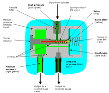
These are systems used to supply breathing gas on demand in a chamber which is at a pressure greater than the ambient pressure outside the chamber.[23] The pressure difference between chamber and external ambient pressure makes it possible to exhaust the exhaled gas to the external environment, but the flow must be controlled so that only exhaled gas is vented through the system, and it does not drain the contents of the chamber to the outside. This is achieved by using a controlled exhaust valve which opens when a slight over-pressure relative to the chamber pressure on the exhaust diaphragm moves the valve mechanism against a spring. When this over-pressure is dissipated by the gas flowing out through the exhaust hose, the spring returns this valve to the closed position, cutting off further flow, and conserving the chamber atmosphere. A negative or zero pressure difference over the exhaust diaphragm will keep it closed. The exhaust diaphragm is exposed to the chamber pressure on one side, and exhaled gas pressure in the oro-nasal mask on the other side. This is a form of back-pressure regulator. The supply of gas for inhalation is through a demand valve which works on the same principles as a regular diving demand valve second stage. Like any other breathing apparatus, the dead space must be limited to minimise carbon dioxide buildup in the mask.
BIBS regulators for hyperbaric chambers have a two-stage system at the diver similar to reclaim helmets, though for this application the outlet regulator dumps the exhaled gas through an outlet hose to the atmosphere outside the chamber. In some cases the outlet suction must be limited and an additional back-pressure regulator, a device that maintains a specified pressure upstream of itself, may be required. This would usually be the case for use in a saturation system. Use for oxygen therapy and surface decompression on oxygen would not generally need a back-pressure regulator as the chamber pressure is relatively low.[25] When an externally vented BIBS is used at low chamber pressure, a vacuum assist may be necessary to keep the exhalation back-pressure down to provide an acceptable work of breathing.[23]
The major application for this type of BIBS is supply of breathing gas with a different composition to the chamber atmosphere to occupants of a hyperbaric chamber where the chamber atmosphere is controlled, and contamination by the BIBS gas would be a problem.[23] This is common in therapeutic decompression, and hyperbaric oxygen therapy, where a higher partial pressure of oxygen in the chamber would constitute an unacceptable fire hazard, and would require frequent ventilation of the chamber to keep the partial pressure within acceptable limits Frequent ventilation is noisy and expensive, but can be used in an emergency.[24]
References
- Harlow, Vance (1999). "1 How a regulator works". Scuba regulator maintenance and repair. Warner, New Hampshire: Airspeed Press. pp. 1–26. ISBN 0-9678873-0-5.
- Harlow, Vance (1999). Scuba regulator maintenance and repair. Warner, New Hampshire: Airspeed Press. ISBN 0-9678873-0-5.
- Staff. "San-o-Sub DIN/K Cylinder Valve - 232 bar". Melbourne, Victoria: The Scuba Doctor. Retrieved 6 January 2016.
- Staff. "How to select a SCUBA tank". divegearexpress.com. Pompano Beach, Florida: Dive Gear Express, LLC. Archived from the original on 15 April 2015. Retrieved 8 November 2016.
- Staff (August 1999). "DrägerRay Mixed Gas-Rebreather Instructions for Use" (PDF). 90 21 365 - GA 2215.000 de/en (2nd ed.). Lübeck, Germany: Dräger Sicherheitstechnik GmbH. pp. 46–88. Retrieved 8 November 2016.
- Barsky, Steven; Neuman, Tom (2003). Investigating Recreational and Commercial Diving Accidents. Santa Barbara, California: Hammerhead Press. ISBN 0-9674305-3-4.
- "Environmental Dry Sealing System". First Stage Technology. Blackburn, United Kingdom: Apeks Marine Equipment. Archived from the original on 17 November 2016. Retrieved 17 November 2016.
Standard on most Apeks first stages is the unique Environmental Dry Sealing System. This system serves a number of purposes, including the prevention of ice build up on the main spring that can occur when diving in extremely cold water. Dry sealing the first stage also acts as a safeguard against the entry of contaminants and silt into the main spring chamber, and eliminates the need for messy silicone oil or grease filling inside your regulator.
- Staff. "KM Over Pressure Relief Valve, Hi-Flow". Products. Santa Maria California: Diving Equipment Company of America (DECA). Retrieved 16 November 2016.
- Barsky, Steven (2007). Diving in High-Risk Environments (4th ed.). Ventura, California: Hammerhead Press. ISBN 978-0-9674305-7-7.
- Brittain, Colin (2004). "Protective clothing, scuba equipment and equipment maintenance". Let's Dive: Sub-Aqua Association Club Diver Manual (2nd ed.). Wigan, UK: Dive Print. p. 35. ISBN 0-9532904-3-3. Retrieved 6 January 2010.
- Brittain, Colin (2004). "Practical diver training". Let's Dive: Sub-Aqua Association Club Diver Manual (2nd ed.). Wigan, UK: Dive Print. p. 48. ISBN 0-9532904-3-3. Retrieved 6 January 2010.
- Vintage European Two Hose Regulator Collection
- Staff (16 February 2005). "Aqua Lung Debuts the Comeback of the Double Hose Regulator". Sport Diver. Bonnier corporation. Retrieved 16 May 2017.
- Warren, Steve (November 2015). "The History Boys". Divernet - Gear features. divernet.com. Retrieved 16 May 2017.
- Roberts, Fred M. (1963). Basic Scuba. Self-Contained Underwater Breathing Apparatus: Its Operation, Maintenance and Use (Enlarged Second ed.). New York: Van Nostrand Reinhold Co. ISBN 0-442-26824-6.
- Busuttili, Mike; Holbrook, Mike; Ridley, Gordon; Todd, Mike, eds. (1985). "The Aqualung". Sport diving – The British Sub-Aqua Club Diving Manual. London: Stanley Paul & Co Ltd. p. 36. ISBN 0-09-163831-3.
- "Divex Diver Umbilicals" (PDF). Divex. Retrieved 20 March 2020.
- ref from PDC training manual? IMCA sup man?
- "Reclaim Basic Set Up" (PDF). www.subseasa.com. Retrieved 10 March 2020.
- Bevan, John, ed. (2005). "Section 5.3". The Professional Divers's Handbook (second ed.). Gosport, Hampshire: Submex Ltd. p. 238. ISBN 978-0950824260.
- Operation and Maintenance Manual for the 17C Ultrajewel 601 Helmet Part Number: A10170 Document Number: P1884-OM-56 (Revision: 8 ed.). JFD Divex.
- "Ultralite 2 BIBS Mask (DE-MDS-540-R0)" (PDF). Divex. Retrieved 25 September 2018.
- U.S. Navy Supervisor of Diving (April 2008). "Chapter 21: Recompression Chamber Operation". U.S. Navy Diving Manual. Volume 5: Diving Medicine and Recompression Chamber Operations (PDF). SS521-AG-PRO-010, Revision 6. U.S. Naval Sea Systems Command. Archived (PDF) from the original on March 31, 2014. Retrieved 2009-06-29.
- "A Lightweight, and Extremely Robust, Built in Breathing System for Hyperbaric Chambers" (PDF). Aberdeen, Scotland: C-Tecnics Ltd. Archived from the original (PDF) on 25 September 2018. Retrieved 25 September 2018.