Flywheel
A flywheel is a mechanical device specifically designed to efficiently store rotational energy (kinetic energy), which is proportional to the square of its rotational speed and its mass. Flywheels resist changes in rotational speed by their moment of inertia and in order to change a flywheel's stored energy (without changing its mass) its rotational speed must be increased or decreased. Since flywheels act as mechanical energy storage devices, they are the kinetic-energy-storage analogue to electrical inductors, for example, which are a type of accumulator. Like other types of accumulators, flywheels smooth the ripple in power output, providing surges of high power output as required, absorbing surges of high power input (system-generated power) as required, and in this way act as low-pass filters on the mechanical velocity (angular, or otherwise) of the system.
.jpg)

Common uses of a flywheel include:
- Smoothing the power output of an energy source. For example, flywheels are used in reciprocating engines because the active torque from the individual pistons is intermittent.
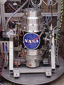
- Energy storage systems
- Delivering energy at rates beyond the ability of an energy source. This is achieved by collecting energy in a flywheel over time and then releasing it quickly, at rates that exceed the abilities of the energy source.
- Controlling the orientation of a mechanical system, gyroscope and reaction wheel
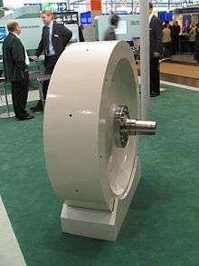
Flywheels are typically made of steel and rotate on conventional bearings; these are generally limited to a maximum revolution rate of a few thousand RPM.[1] High energy density flywheels can be made of carbon fiber composites and employ magnetic bearings, enabling them to revolve at speeds up to 60,000 RPM (1 kHz).[2]
Carbon-composite flywheel batteries have recently been manufactured and are proving to be viable in real-world tests on mainstream cars. Additionally, their disposal is more eco-friendly than traditional lithium ion batteries.[3]
Applications
2.JPG)
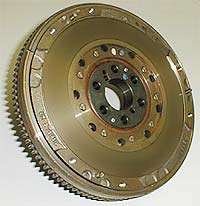
Flywheels are often used to provide continuous power output in systems where the energy source is not continuous. For example, a flywheel is used to smooth fast angular velocity fluctuations of the crankshaft in a reciprocating engine. In this case, a crankshaft flywheel stores energy when torque is exerted on it by a firing piston, and returns it to the piston to compress a fresh charge of air and fuel. Another example is the friction motor which powers devices such as toy cars. In unstressed and inexpensive cases, to save on cost, the bulk of the mass of the flywheel is toward the rim of the wheel. Pushing the mass away from the axis of rotation heightens rotational inertia for a given total mass.
A flywheel may also be used to supply intermittent pulses of energy at power levels that exceed the abilities of its energy source. This is achieved by accumulating energy in the flywheel over a period of time, at a rate that is compatible with the energy source, and then releasing energy at a much higher rate over a relatively short time when it is needed. For example, flywheels are used in power hammers and riveting machines.
Flywheels can be used to control direction and oppose unwanted motions, see gyroscope. Flywheels in this context have a wide range of applications from gyroscopes for instrumentation to ship stability and satellite stabilization (reaction wheel), to keep a toy spin spinning (friction motor), to stabilize magnetically levitated objects (Spin-stabilized magnetic levitation)
Flywheels may also be used as an electric compensator, like a synchronous compensator, that can either produce or sink reactive power but would not affect the real power. The purposes for that application are to improve the power factor of the system or adjust the grid voltage. Typically, the flywheels used in this field are similar in structure and installation as the synchronous motor (but it is called synchronous compensator or synchronous condenser in this context). There are also some other kinds of compensator using flywheels, like the single phase induction machine. But the basic ideas here are the same, the flywheels are controlled to spin exactly at the frequency which you want to compensate. For a synchronous compensator, you also need to keep the voltage of rotor and stator in phase, which is the same as keeping the magnetic field of rotor and the total magnetic field in phase (in the rotating frame reference).
History
The principle of the flywheel is found in the Neolithic spindle and the potter's wheel, as well as circular sharpening stones in antiquity.[4]
The mechanical flywheel, used to smooth out the delivery of power from a driving device to a driven machine and, essentially, to allow lifting water from far greater depths (up to 200 metres (660 ft)), was first employed by Ibn Bassal (fl. 1038–1075), of Al-Andalus.[5][6][7][8]
The use of the flywheel as a general mechanical device to equalize the speed of rotation is, according to the American medievalist Lynn White, recorded in the De diversibus artibus (On various arts) of the German artisan Theophilus Presbyter (ca. 1070–1125) who records applying the device in several of his machines.[4][9]
In the Industrial Revolution, James Watt contributed to the development of the flywheel in the steam engine, and his contemporary James Pickard used a flywheel combined with a crank to transform reciprocating motion into rotary motion.
Physics
A flywheel is a spinning wheel, or disc, or rotor, rotating around its symmetry axis. Energy is stored as kinetic energy, more specifically rotational energy, of the rotor:

where:
- is the stored kinetic energy,
- ω is the angular velocity, and
- is the moment of inertia of the flywheel about its axis of symmetry. The moment of inertia is a measure of resistance to torque applied on a spinning object (i.e. the higher the moment of inertia, the slower it will accelerate when a given torque is applied).
- The moment of inertia for a solid cylinder is ,
- for a thin-walled empty cylinder is ,
- and for a thick-walled empty cylinder is ,[10]


where denotes mass, and denotes a radius.


When calculating with SI units, the units would be for mass, kilograms; for radius, meters; and for angular velocity, radians per second and the resulting energy would be in joules.
Increasing amounts of rotation energy can be stored in the flywheel until the rotor shatters. This happens when the hoop stress within the rotor exceeds the ultimate tensile strength of the rotor material.

where:
- is the tensile stress on the rim of the cylinder
- is the density of the cylinder
- is the radius of the cylinder, and
- is the angular velocity of the cylinder.


A flywheel powered by electric machine is common. The output power of the electric machine is approximately equal to the output power of the flywheel.
The output power of a synchronous machine is:

where:
- is the voltage of rotor winding, which is produced by field interacting with the stator winding
- is stator voltage
- is the torque angle (angle between two voltages)


Material selection
Flywheels are made from many different materials; the application determines the choice of material. Small flywheels made of lead are found in children's toys. Cast iron flywheels are used in old steam engines. Flywheels used in car engines are made of cast or nodular iron, steel or aluminum.[11] Flywheels made from high-strength steel or composites have been proposed for use in vehicle energy storage and braking systems.
The efficiency of a flywheel is determined by the maximum amount of energy it can store per unit weight. As the flywheel's rotational speed or angular velocity is increased, the stored energy increases; however, the stresses also increase. If the hoop stress surpass the tensile strength of the material, the flywheel will break apart. Thus, the tensile strength limits the amount of energy that a flywheel can store.
In this context, using lead for a flywheel in a child's toy is not efficient; however, the flywheel velocity never approaches its burst velocity because the limit in this case is the pulling-power of the child. In other applications, such as an automobile, the flywheel operates at a specified angular velocity and is constrained by the space it must fit in, so the goal is to maximize the stored energy per unit volume. The material selection therefore depends on the application.[12]
The table below contains calculated values for materials and comments on their viability for flywheel applications. CFRP stands for carbon-fiber-reinforced polymer, and GFRP stands for glass-fiber reinforced polymer.
| Material | Specific tensile strength | Comments |
|---|---|---|
| Ceramics | 200–2000 (compression only) | Brittle and weak in tension, therefore eliminate |
| Composites: CFRP | 200–500 | The best performance—a good choice |
| Composites: GFRP | 100–400 | Almost as good as CFRP and cheaper |
| Beryllium | 300 | The best metal, but expensive, difficult to work with, and toxic to machine |
| High strength steel | 100–200 | Cheaper than Mg and Ti alloys |
| High strength Al alloys | 100–200 | Cheaper than Mg and Ti alloys |
| High strength Mg alloys | 100–200 | About equal performance to steel and Al-alloys |
| Ti alloys | 100–200 | About equal performance to steel and Al-alloys |
| Lead alloys | 3 | Very low |
| Cast Iron | 8–10 | Very low[13] |

The table below shows calculated values for mass, radius, and angular velocity for storing 250 J. The carbon-fiber flywheel is by far the most efficient; however, it also has the largest radius. In applications (like in an automobile) where the volume is constrained, a carbon-fiber flywheel might not be the best option.
| Material | Energy storage (J) | Mass (kg) | Radius (m) | Angular velocity (rpm) | Efficiency (J/kg) | Energy density (kWh/kg) |
|---|---|---|---|---|---|---|
| Cast Iron | 250 | 0.0166 | 1.039 | 1465 | 15060 | 0.0084 |
| Aluminum Alloy | 250 | 0.0033 | 1.528 | 2406 | 75760 | 0.0421 |
| Maraging steel | 250 | 0.0044 | 1.444 | 2218 | 56820 | 0.0316 |
| Composite: CFRP (40% epoxy) | 250 | 0.001 | 1.964 | 3382 | 250000 | 0.1389 |
| Composite: GFRP (40% epoxy) | 250 | 0.0038 | 1.491 | 2323 | 65790[14] | 0.0365 |
Table of energy storage traits
| Flywheel purpose, type | Geometric shape factor (k) (unitless – varies with shape) |
Mass (kg) |
Diameter (cm) |
Angular velocity (rpm) |
Energy stored (MJ) |
Energy stored (kWh) |
Energy density (kWh/kg) |
|---|---|---|---|---|---|---|---|
| Small battery | 0.5 | 100 | 60 | 20,000 | 9.8 | 2.7 | 0.027 |
| Regenerative braking in trains | 0.5 | 3000 | 50 | 8,000 | 33.0 | 9.1 | 0.003 |
| Electric power backup[15] | 0.5 | 600 | 50 | 30,000 | 92.0 | 26.0 | 0.043[16][17][18][19] |
For comparison, the energy density of petrol (gasoline) is 44.4 MJ/kg or 12.3 kWh/kg.
High-energy materials
For a given flywheel design, the kinetic energy is proportional to the ratio of the hoop stress to the material density and to the mass:

could be called the specific tensile strength. The flywheel material with the highest specific tensile strength will yield the highest energy storage per unit mass. This is one reason why carbon fiber is a material of interest.

For a given design the stored energy is proportional to the hoop stress and the volume:

Design
Rimmed
A rimmed flywheel has a rim, a hub, and spokes.[20] Calculation of the flywheel's moment of inertia can be more easily analysed by applying various simplifications. For example:
- Assume the spokes, shaft and hub have zero moments of inertia, and the flywheel's moment of inertia is from the rim alone.
- The lumped moments of inertia of spokes, hub and shaft may be estimated as a percentage of the flywheel's moment of inertia, with the majority from the rim, so that

For example, if the moments of inertia of hub, spokes and shaft are deemed negligible, and the rim's thickness is very small compared to its mean radius (), the radius of rotation of the rim is equal to its mean radius and thus:


Shaftless
A shaftless flywheel eliminates the annulus holes, shaft or hub. It has higher energy density than conventional design[21] but requires a specialized magnetic bearing and control system.[22]
The specific energy of a flywheel is determined by

In which is the shape factor, the material's tensile strength and the density. A typical flywheel has a shape factor of 0.3. Better designs, such as the shaftless flywheel, have a shape factor close to 0.6, the theoretical limit is about 1.[23]


See also
References
- "Flywheels move from steam age technology to Formula 1". Archived from the original on 2012-07-03. Retrieved 2012-07-03.; "Flywheels move from steam age technology to Formula 1"; Jon Stewart | 1 July 2012, retrieved 2012-07-03
- "Breakthrough in Ricardo Kinergy 'second generation' high-speed flywheel technology". 2011-08-21. Archived from the original on 2012-07-05. Retrieved 2012-07-03., "Breakthrough in Ricardo Kinergy ‘second generation’ high-speed flywheel technology"; Press release date: 22 August 2011. retrieved 2012-07-03
- "10 Need-to-Know Tech Concepts for 2012". popularmechanics.com. 3 January 2012. Archived from the original on 11 November 2013. Retrieved 2 May 2018.
- Lynn White, Jr., "Theophilus Redivivus", Technology and Culture, Vol. 5, No. 2. (Spring, 1964), Review, pp. 224–233 (233)
- Letcher, Trevor M. (2017). Wind energy engineering: a handbook for onshore and offshore wind turbines. Academic Press. pp. 127–143. ISBN 978-0128094518.
Ibn Bassal (AD 1038–75) of Al Andalus (Andalusia) pioneered the use of a flywheel mechanism in the noria and saqiya to smooth out the delivery of power from the driving device to the driven machine
- Ahmad Y Hassan, Flywheel Effect for a Saqiya.
- "Flywheel" (PDF). themechanic.weebly.com.
- Shabbir, Asad. "The Role of Muslim Mechanical Engineers In Modern Mechanical Engineering Dedicate to12th Century Muslim Mechanical Engineer" (PDF). Islamic Research Foundation International, Inc.
- Lynn White, Jr., "Medieval Engineering and the Sociology of Knowledge", The Pacific Historical Review, Vol. 44, No. 1. (Feb., 1975), pp. 1–21 (6)
- "Archived copy" (PDF). Archived (PDF) from the original on 2012-01-05. Retrieved 2011-12-01.CS1 maint: archived copy as title (link) (page 10, accessed 1 Dec 2011, Moment of inertia tutorial
- "Flywheels: Iron vs. Steel vs. Aluminum". Fidanza Performance. Archived from the original on 10 October 2016. Retrieved 6 October 2016.
- Ashby, Michael (2011). Materials Selection in Mechanical Design (4th ed.). Burlington, MA: Butterworth-Heinemann. pp. 142–146. ISBN 978-0-08-095223-9.
- Totten, George E.; Xie, Lin; Funatani, Kiyoshi (2004). Handbook of Mechanical Alloy Design. New York: Marcel Dekker. ISBN 978-0-8247-4308-6.
- Kumar, Mouleeswaran Senthil; Kumar, Yogesh (2012). "Optimization of Flywheel Materials Using Genetic Algorithm" (PDF). Acta Technica Corviniensis-Bulletin of Engineering. Archived (PDF) from the original on 1 November 2015. Retrieved 1 November 2015.
- "Flywheel Energy Storage, UPS, Battery-Free, Active Magnetic Bearing, Magnetic Bearings, Kinetic Energy, Magnet Motor Generator, Bi-Directional Power Converter - Calnetix". www.calnetix.com. Archived from the original on 1 November 2017. Retrieved 2 May 2018.
- "Flywheel Energy Calculator". Botlanta.org. 2004-01-07. Archived from the original on 2011-07-25. Retrieved 2010-11-30.
- "energy buffers". Home.hccnet.nl. Archived from the original on 2010-11-26. Retrieved 2010-11-30.
- "Message from the Chair | Department of Physics | University of Prince Edward Island". Upei.ca. Archived from the original on 2010-04-30. Retrieved 2010-11-30.
- "Density of Steel". Hypertextbook.com. 1998-01-20. Archived from the original on 2010-11-25. Retrieved 2010-11-30.
- Flywheel Rotor And Containment Technology Development, FY83. Livermore, Calif: Lawrence Livermore National Laboratory , 1983. pp. 1–2
- Li, Xiaojun; Anvari, Bahar; Palazzolo, Alan; Wang, Zhiyang; Toliyat, Hamid (2018-08-14). "A Utility Scale Flywheel Energy Storage System with a Shaftless, Hubless, High Strength Steel Rotor". IEEE Transactions on Industrial Electronics. 65 (8): 6667–6675. doi:10.1109/TIE.2017.2772205.
- Li, Xiaojun; Palazzolo, Alan (2018-05-07). "Multi-Input–Multi-Output Control of a Utility-Scale, Shaftless Energy Storage Flywheel With a Five-Degrees-of-Freedom Combination Magnetic Bearing". Journal of Dynamic Systems, Measurement, and Control. 140 (10): 101008. doi:10.1115/1.4039857. ISSN 0022-0434.
- Genta, G. (1985), "Application of flywheel energy storage systems", Kinetic Energy Storage, Elsevier, pp. 27–46, doi:10.1016/b978-0-408-01396-3.50007-2, ISBN 9780408013963
- Weissbach, R. S.; Karady, G.G.; Farmer, R. G. (April 2001). "A combined uninterruptible power supply and dynamic voltage compensator using a flywheel energy storage system". IEEE Transactions on Power Delivery. 16 (2): 265–270. doi:10.1109/61.915493. ISSN 0885-8977.
- "Synchronous Generators I" (PDF).
- https://pserc.wisc.edu/documents/general_information/presentations/presentations_by_pserc_university_members/heydt_synchronous_mach_sep03.pdf
External links
| Look up flywheel in Wiktionary, the free dictionary. |

- Flywheel batteries on Interesting Thing of the Day.
- Flywheel-based microgrid stabilisation technology., ABB
- PowerStore