Crankshaft
A crankshaft is a rotating shaft which (in conjunction with the connecting rods) converts reciprocating motion of the pistons into rotational motion. Crankshafts are commonly used in internal combustion engines and consist of a series of cranks and crankpins to which the connecting rods are attached.[1]
The crankshaft rotates within the engine block through use of main bearings, and the crankpins rotate within the connecting rods using rod bearings. Crankshafts are usually made from metal, with most modern crankshafts being constructed using forged steel.
History
Western World
Classical Antiquity
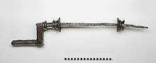
A Roman iron crankshaft of yet unknown purpose dating to the 2nd century AD was excavated in Augusta Raurica, Switzerland. The 82.5 cm long piece has fitted to one end a 15 cm long bronze handle, the other handle being lost.[3][2]
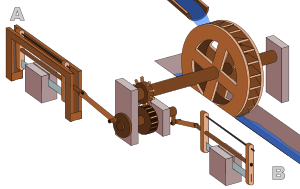
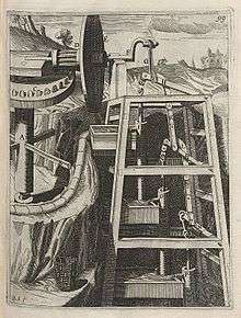
The earliest evidence for a crank and connecting rod in a machine appears in the late Roman Hierapolis sawmill from the 3rd century AD and two Roman stone sawmills at Gerasa, Roman Syria, and Ephesus, Asia Minor (both 6th century AD).[4] On the pediment of the Hierapolis mill, a waterwheel fed by a mill race is shown transmitting power through a gear train to two frame saws, which cut rectangular blocks by way of some kind of connecting rods and, through mechanical necessity, cranks. The accompanying inscription is in Greek.[5]
The crank and connecting rod mechanisms of the other two archaeologically attested sawmills worked without a gear train.[6][7] In ancient literature, we find a reference to the workings of water-powered marble saws close to Trier, now Germany, by the late 4th century poet Ausonius;[4] about the same time, these mill types seem also to be indicated by the Christian saint Gregory of Nyssa from Anatolia, demonstrating a diversified use of water-power in many parts of the Roman Empire.[8] The three finds push back the date of the invention of the crank and connecting rod back by a full millennium;[4] for the first time, all essential components of the much later steam engine were assembled by one technological culture:
With the crank and connecting rod system, all elements for constructing a steam engine (invented in 1712) — Hero's aeolipile (generating steam power), the cylinder and piston (in metal force pumps), non-return valves (in water pumps), gearing (in water mills and clocks) — were known in Roman times.[9]
Middle Ages
.jpeg)
The Italian physician Guido da Vigevano (c. 1280−1349), planning for a new crusade, made illustrations for a paddle boat and war carriages that were propelled by manually turned compound cranks and gear wheels (center of image).[10] The Luttrell Psalter, dating to around 1340, describes a grindstone rotated by two cranks, one at each end of its axle; the geared hand-mill, operated either with one or two cranks, appeared later in the 15th century;[11]
Renaissance
The first depictions of the compound crank in the carpenter's brace appear between 1420 and 1430 in various northern European artwork.[12] The rapid adoption of the compound crank can be traced in the works of the Anonymous of the Hussite Wars, an unknown German engineer writing on the state of the military technology of his day: first, the connecting-rod, applied to cranks, reappeared, second, double compound cranks also began to be equipped with connecting-rods and third, the flywheel was employed for these cranks to get them over the 'dead-spot'.[13]
In Renaissance Italy, the earliest evidence of a compound crank and connecting-rod is found in the sketch books of Taccola, but the device is still mechanically misunderstood.[13] A sound grasp of the crank motion involved demonstrates a little later Pisanello who painted a piston-pump driven by a water-wheel and operated by two simple cranks and two connecting-rods.[13]
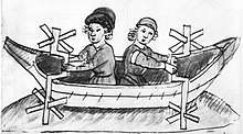
One of the drawings of the Anonymous of the Hussite Wars shows a boat with a pair of paddle-wheels at each end turned by men operating compound cranks (see above). The concept was much improved by the Italian Roberto Valturio in 1463, who devised a boat with five sets, where the parallel cranks are all joined to a single power source by one connecting-rod,[14] an idea also taken up by his compatriot Francesco di Giorgio.[15]
Crankshafts were also described by Konrad Kyeser (d. 1405), Leonardo da Vinci (1452–1519)[16] and a Dutch "farmer" by the name Cornelis Corneliszoon van Uitgeest in 1592. His wind-powered sawmill used a crankshaft to convert a windmill's circular motion into a back-and-forward motion powering the saw. Corneliszoon was granted a patent for his crankshaft in 1597.
From the 16th century onwards, evidence of cranks and connecting rods integrated into machine design becomes abundant in the technological treatises of the period: Agostino Ramelli's The Diverse and Artifactitious Machines of 1588 alone depicts eighteen examples, a number that rises in the Theatrum Machinarum Novum by Georg Andreas Böckler to 45 different machines, one third of the total.[17]
Middle and Far East
Al-Jazari (1136–1206) described a crank and connecting rod system in a rotating machine in two of his water-raising machines.[16] His twin-cylinder pump incorporated a crankshaft,[18] but the device was unnecessarily complex indicating that he still did not fully understand the concept of power conversion.[19] In China, the potential of the crank of converting circular motion into reciprocal one never seems to have been fully realized, and the crank was typically absent from such machines until the turn of the 20th century.[20]
Design
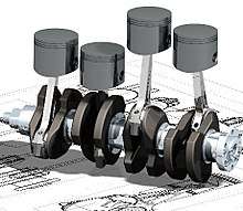
The crankshaft is supported by the engine block, with the engine's main bearings allowing the crankshaft to rotate within the block. The up-down motion of each piston is transferred to the crankshaft via connecting rods. A flywheel is often attached to one end of the crankshaft, in order to store rotational energy and maintain a more consistent rotational speed as the crankshaft received energy from the connecting rods as a series of pulses. This assists in smoothing the power delivery and often in conjunction with a Harmonic damper -attached to the other end of crankshaft- reduces torsional vibration.
A crankshaft is subjected to enormous stresses, in some cases more than 8.6 tonnes (19,000 pounds) per cylinder.[21] Crankshafts for single-cylinder engines are usually a simpler design than for engines with multiple cylinders.
Crankshafts can either be one-piece forgings or pressed together from separate individual crank-webs, shafts and pins, sometimes called a 'built-up crankshaft'. In most automotive applications (Four-stroke engines) a one-piece forging is used in conjunction with plain/shell bearings that rely on steady supply of pressurized engine oil. This pressurized oil fills the clearance between the bearings and the journals of the crankshaft and creates a thin hydrodynamic layer of oil that 'floats' the metal surfaces apart so no metal to metal contact occurs as the parts rotate. This oil film is very low friction and, as long as oil pressure is maintained, can easily handle the forces generated by piston acceleration, deceleration, reversal and swing of conrod big ends.
Two-stroke engines use a sealed crankcase as part of the induction of fresh fuel/air into the cylinder. This precludes the use of oil pressurized plain main and crankpin bearings. Instead rolling element ball and needle roller bearings are used and the cranks shaft is made up of several pieces press-fitted together using one-piece conrods, rather than the 2-piece conrod design ubiquitous in a plain bearing 4-stroke engine. Lubrication of the two-stroke crankshaft is via oil mixed with fuel, either in the fuel tank (pre-mix) or via a separate oiling system that delivers oil to the crankcase to be mixed with the fuel according to rpm and load. While mainly used in two-stroke engines (everything from chainsaws to large multi-cylinder outboard motors) some older 4-stroke engines (mainly motorcycles) use built up roller crankshafts.
Bearings
The crankshaft is able to rotate in the engine block due to the main bearings. Since the crankshaft is subject to large sideways forces from each cylinder, bearings are located at various points along the crankshaft, not just one at each end. This was a factor in V8 engines replacing straight-eight engines in the 1950s. The long crankshafts of the latter suffered from an unacceptable amount of flex when engine designers began using higher compression ratios and higher engine speeds (RPM). High performance engines often have more main bearings than their lower performance cousins for this reason.
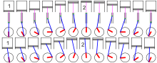
Cross-plane vs flat-plane
Most production V8 engines use crank throws spaced 90° apart, which is called a "cross-plane" configuration (such as the Ford Modular engine and the General Motors LS engine). Several high-performance V8 engines (such as the Ferrari 355) instead use use a "flat-plane" crankshaft with throws spaced 180° apart, essentially resulting in two inline-four engines running in a common crankcase.
Flat-plane engines are usually able to rev higher, however they have more vibration. Flat-plane crankshafts were used on several early V8 engines. See the main article on crossplane crankshafts.
Engine balance
For some engines it is necessary to provide counterweights for the reciprocating mass of each piston and connecting rod to improve engine balance. These are typically cast as part of the crankshaft but, occasionally, are bolt-on pieces.
In 1916, the Hudson Motor Car Company began production of the first engines to use balanced crankshafts, which allowed the engine to run at higher speeds (RPM) than contemporary engines.
Flying arms

In some engines, the crankshaft contains direct links between adjacent crank pins, without the usual intermediate main bearing. These links are called flying arms.[22](pp16, 41) This arrangement is sometimes used in V6 and V8 engines, as it enables the engine to be designed with different V angles than what would otherwise be required to create an even firing interval, while still using fewer main bearings than would normally be required with a single piston per crankthrow. This arrangement reduces weight and engine length at the expense of reduced crankshaft rigidity.
Piston stroke
The distance the axis of the crank throws from the axis of the crankshaft determines the stroke length of the engine.
Most modern car engines are classified as "over square" or short-stroke, wherein the stroke is less than the diameter of the cylinder bore. A common way to increase the low-RPM torque of an engine is to increase the stroke, sometimes known as "stroking" the engine. Traditionally, the trade-off for a long-stroke engine was reduced power and increased vibration at high RPM.
Counterweights
Some high performance crankshafts also use heavy-metal counterweights to make the crankshaft more compact. The heavy-metal used is most often a tungsten alloy but depleted uranium has also been used. A cheaper option is to use lead, but compared with tungsten its density is much lower.
Counter-rotating crankshafts
The conventional design for piston engines is where each connecting rod is attached to one crankshaft, with the angle of the connecting rod varying as the piston moves through its stroke. This variation in angle results in lateral forces on the pistons, pushing the pistons against the cylinder wall. This lateral force causes additional friction between the piston and cylinder wall[23] and can cause additional wear on the cylinder wall.
To avoid these lateral forces, each piston can be connected to two crankshafts that are rotating in opposite directions, which cancels out the lateral forces. This arrangement also reduces the requirement for counterweights, reducing the mass of the crankshaft. An early example of a counter-rotating crankshaft arrangement is the 1900-1904 Lanchester Engine Company flat-twin engines.
Full Crank vs Half Crank
On small single cylinder engines, to reduce cost and weight, one of the crank shaft bearings is sometimes omitted. Full crank designs are considered to be smoother running and to last longer. [24]
Construction
Forging, casting and machining
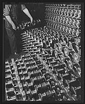
The most common construction methods for crankshafts are forging (usually through roll forging) or casting. Most crankshafts are made in a single piece, however some smaller and larger engines use crankshafts assembled from multiple pieces.
Recently, forging has become the most common construction method for crankshafts, due to their lighter weight, more compact dimensions and better inherent damping. With forged crankshafts, vanadium microalloyed steels are mostly used as these steels can be air cooled after reaching high strengths without additional heat treatment (aside from the surface hardening of the bearing journals). The low alloy content also makes the material cheaper than high alloy steels.
Casting (using cast iron) is today mostly used for crankshafts in cheaper, lower performance engines.
Crankshafts can also be machined out of a billet of steel. These crankshafts tend to be expensive due to the large amount of material that must be removed with lathes and milling machines, the high material cost, and the additional heat treatment required. Since no expensive tooling is needed, this production method is mostly used for low-volume engines. In a machined crankshafts, the fibre flow (local inhomogeneities of the material caused by the casting process) does not follow the shape of the crankshaft, however this is rarely a problem since machined crankshafts often use higher quality steels than forged crankshafts.
Fatigue strength
To improve the fatigue strength, a radius is often rolled at the ends of each main and crankpin bearing. The radius itself reduces the stress in these critical areas, but since the radius in most cases is rolled, this also leaves some compressive residual stress in the surface, which prevents cracks from forming.
Microfinishing is a grinding process to produce a smooth finish on the surface of a metallic object, which is also used to prevent cracks developing from fatigue stress.
Bearing surfaces
Most mass-production crankshafts use induction hardening for the bearing surfaces. Some high performance crankshafts, billet crankshafts in particular, use nitridization instead. For crankshafts that operate on roller bearings, the use of carburization tends to be favored due to the high contact stresses in such situations.
See also
| Wikimedia Commons has media related to Crankshaft. |
References
- "Definition of CRANKSHAFT". Merriam-Webster Dictionary.
- Schiöler 2009, pp. 113f.
- Laur-Belart 1988, p. 51–52, 56, fig. 42
- Ritti, Grewe & Kessener 2007, p. 161:
Because of the findings at Ephesus and Gerasa the invention of the crank and connecting rod system has had to be redated from the 13th to the 6th c; now the Hierapolis relief takes it back another three centuries, which confirms that water-powered stone saw mills were in use when Ausonius wrote his Mosella.
- Ritti, Grewe & Kessener 2007, pp. 139–141
- Ritti, Grewe & Kessener 2007, pp. 149–153
- Mangartz 2010
- Wilson 2002, p. 16
- Ritti, Grewe & Kessener 2007, p. 156, fn. 74
- Hall 1979, p. 80
- White, Jr. 1962, p. 111
- White, Jr. 1962, p. 112
- White, Jr. 1962, p. 113
- See this illustration (top)
- White, Jr. 1962, p. 114
- Ahmad Y Hassan. The Crank-Connecting Rod System in a Continuously Rotating Machine.
- White, Jr. 1962, p. 172
- Sally Ganchy, Sarah Gancher (2009), Islam and Science, Medicine, and Technology, The Rosen Publishing Group, p. 41, ISBN 1-4358-5066-1
- White, Jr. 1962, p. 170:
However, that al-Jazari did not entirely grasp the meaning of the crank for joining reciprocating with rotary motion is shown by his extraordinarily complex pump powered through a cog-wheel mounted eccentrically on its axle.
- White, Jr. 1962, p. 104:
Yet a student of the Chinese technology of the early twentieth century remarks that even a generation ago the Chinese had not 'reached that stage where continuous rotary motion is substituted for reciprocating motion in technical contrivances such as the drill, lathe, saw, etc. To take this step familiarity with the crank is necessary. The crank in its simple rudimentary form we find in the [modern] Chinese windlass, which use of the device, however, has apparently not given the impulse to change reciprocating into circular motion in other contrivances'. In China the crank was known, but remained dormant for at least nineteen centuries, its explosive potential for applied mechanics being unrecognized and unexploited.
- "How to Build Racing Engines: Crankshafts Guide". www.musclecardiy.com. 5 April 2015. Retrieved 27 October 2019.
- Nunney, Malcolm J. (2007). Light and Heavy Vehicle Technology (4th ed.). Elsevier Butterworth-Heinemann. ISBN 978-0-7506-8037-0.
- Andersson BS (1991), Company's perspective in vehicle tribology. In: 18th Leeds-Lyon Symposium (eds D Dowson, CM Taylor and MGodet), Lyon, France, 3-6 September 1991, New York: Elsevier, pp. 503–506
- http://www.powerequipmentdiscounters.com.au/index.php?main_page=articlePage&artno=121