Engine configuration
The engine configuration describe the fundamental operating principles by which internal combustion engines are categorised.
Piston engines are often categorised by their cylinder layout, valves and camshafts. Wankel engines are often categorised by the number of rotors present. Gas turbine engines are often categorised into turbojets, turbofans, turboprops and turboshafts.
Piston engines
Cylinder layout
Single cylinder engines
Straight / inline engines
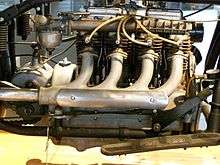
Straight engines, also known as inline engines, have all cylinders aligned in one row along the crankshaft with no offset. When a straight engine is mounted at an angle, it is sometimes called a "slant engine". Types of straight engines include:
- straight-2, also known as "parallel twin"
- straight-3, also known as "inline-triple"
- straight-4, the most common engine for cars
- straight-5
- straight-6
- straight-8
- straight-10
- straight-12
- straight-14
V engines

V engines, also known as Vee engines, have the cylinders aligned in two separate planes or 'banks', so that they appear to be in a "V" when viewed along the axis of the crankshaft. Types of V engines include:
Flat engines
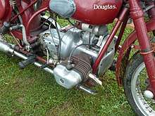
Flat engines, also known as "horizontally-opposed" or "boxer" engines, have the cylinders arranged in two banks on either side of a single crankshaft. Types of flat engines include:
- flat-two, commonly called "flat-twin"
- flat-four
- flat-six
- flat-eight
- flat-twelve
Opposed-piston engines
An opposed-piston engine is like a Flat/boxer engine in that pairs of pistons are co-axial but rather than sharing a crankshaft, instead share a single combustion chamber per pair of pistons. The crankshaft configuration varies amongst opposed-engine designs. One layout has a flat/boxer engine at its center and adds an additional opposed-piston to each end so there are two pistons per cylinder on each side.
W engines
W engines have the cylinders in a configuration in which the cylinder banks resemble the letter W, in the same way those of a V engine resemble the letter V. Types of W engines include:
X engines
An X engine is essentially two V engines joined by a common crankshaft. These were commonly used in aircraft during World War II. A majority of these were existing V-12 engines converted into an X-24 configuration.
U engines
U engines consist of two separate straight engines (complete with separate crankshafts) joined by gears or chains. Most U engines have four-cylinders (i.e. two straight-two engines combined), such as square four engines and tandem twin engines
H engines
Similar to U engines, H engines consist of two separate flat engines joined by gears or chains. H engines have been produced with between 4 and 24 cylinders.
Radial engines
A radial engine has a single crankshaft with cylinders arranged in a planar star shape around the same point on the crankshaft. This configuration was commonly used with 5 air-cooled cylinders in aircraft.
Other layouts
Less common configurations include the Swashplate engine with the K-Cycle engine being one where pairs of pistons are in an opposed configuration sharing a cylinder and combustion chamber.
Valves
The majority of four stroke engines have poppet valves, although some aircraft engines have sleeve valves. Valves may be located in the cylinder block (side valves), or in the cylinder head (overhead valves). Modern engines are invariably of the latter design. There may be two, three, four or five valves per cylinder, with the intake valves outnumbering the exhaust valves in case of an odd number. Interference engines are such engines in which a valve could collide with a piston if the valve timing was incorrect.
Camshafts
Poppet valves are opened by means of a camshaft which revolves at half the crankshaft speed. This can be either chain, gear or toothed belt driven from the crankshaft, and can be located in the crankcase (where it may serve one or more banks of cylinders) or in the cylinder head.
If the camshaft is located in the crankcase, a valve train of pushrods and rocker arms will be required to operate overhead valves. Mechanically simpler are side valves, where the valve stems rested directly on the camshaft However, this gives poor gas flows within the cylinder head as well as heat problems and fell out of favor for automobile use, see flathead engine.
The majority of modern automobile engines place the camshaft on the cylinder head in an overhead camshaft (OHC) design. There may be one or two camshafts in the cylinder head; a single camshaft design is called single overhead camshaft (SOHC). A design with two camshafts per cylinder head is called double overhead camshaft (DOHC). Note that the camshafts are counted per cylinder head, so a V engine with one camshaft in each of its two-cylinder heads is still an SOHC design, and a V engine with two camshafts per cylinder head is DOHC, or informally a "quad cam" engine.[1][2]
With overhead camshafts, the valvetrain will be shorter and lighter, as no pushrods are required. Some overhead camshaft designs still have rocker arms; this facilitates adjustment of mechanical clearances.
A four valves per cylinder design usually has two valves for intake and two for exhaust, which requires two camshafts per cylinder bank. If there are two camshafts in the cylinder head, the cams can sometimes bear directly on cam followers on the valve stems (tappets). The cam followers aid in noise reduction, dampened vibration, shock absorption and the carrying of axial load.[3][4] This latter arrangement is the most inertia free, allows the most unimpeded gas flows in the engine and is the usual arrangement for high performance automobile engines. It also permits the spark plug to be located in the center of the cylinder head, which promotes better combustion characteristics. Beyond a certain number of valves, the effective area covered decreases, so four is the common-most number. Odd numbers of valves necessarily means the intake or exhaust side must have one valve more. In practice this is invariably the intake valves - even in even-numbered head designs, inlet valves are often larger in size than exhaust.
Very large engines (e.g. marine engines) can have either extra camshafts or extra lobes on the camshaft to enable the engine to run in either direction. Furthermore, other manipulations of valves can be used for e.g. engine braking, such as in a Jake brake.
A disadvantage of overhead cams is that a much longer chain (or belt) is needed to drive the cams than with a camshaft located in the cylinder block, usually a tensioner is also needed. A break in the belt may destroy the engine if pistons touch open valves at top dead center.
Wankel (rotary) engines
Wankel engines (sometimes called 'rotary engines') can be classified based on the number of rotors present. Most production Wankel engines have two rotors, however engines with one, three and four rotors have also been produced.[5][6] Wankel engines can also be classified based on whether they are naturally aspirated or turbocharged.
Most Wankel engines are fueled by petrol, however prototype engines running on diesel and hydrogren have been investigated.
Gas turbine engines
Gas turbine engines— mostly used for aircraft— are usually separated into the following categories:
- Turbojet, gasses travel through a propelling nozzle
- Turbofan, gasses travel through a ducted fan
- Turboprop, gasses travel through an unducted propeller, usually with variable pitch
- Turboshaft, a gas turbine optimised for producing mechanical torque instead of thrust
References
- "Camshaft Basics". www.oregoncamshaft.com. Retrieved 2016-02-05.
- "OHV, OHC, SOHC and DOHC (twin cam) engine - Automotive illustrated glossary". Samarins.com. Retrieved 2016-02-05.
- "How Car Engines Work". HowStuffWorks. Retrieved 2016-02-05.
- "Cam Follower Bearings On Emerson Bearing". products.emersonbearing.com. Retrieved 2016-02-05.
- "Technically Interesting: Dr. Wankel's Quad-Rotor Mercedes SL". www.bringatrailer.com. 21 March 2018. Retrieved 31 August 2019.
- "How a Four-Rotor Wankel Engine Works". www.roadandtrack.com. 23 November 2016. Retrieved 31 August 2019.