Fuel pump
A fuel pump is a frequently (but not always) essential component on a car or other internal combustion engined device. Many engines (older motorcycle engines in particular) do not require any fuel pump at all, requiring only gravity to feed fuel from the fuel tank or under high pressure to the fuel injection system. Often, carbureted engines use low pressure mechanical pumps that are mounted outside the fuel tank, whereas fuel injected engines often use electric fuel pumps that are mounted inside the fuel tank (and some fuel injected engines have two fuel pumps: one low pressure/high volume supply pump in the tank and one high pressure/low volume pump on or near the engine).[1] Fuel pressure needs to be within certain specifications for the engine to run correctly. If the fuel pressure is too high, the engine will run rough and rich, not combusting all of the fuel being pumped making the engine inefficient and a pollutant. If the pressure is too low, the engine may run lean, misfire, or stall.
Mechanical pump
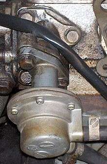
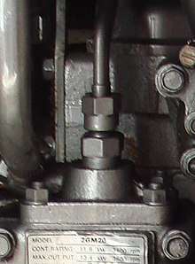
Prior to the widespread adoption of electronic fuel injection, most carbureted automobile engines used mechanical fuel pumps to transfer fuel from the fuel tank into the fuel bowls of the carburetor. The two most widely used fuel feed pumps are diaphragm and plunger-type mechanical pumps. Diaphragm pumps are a type of positive displacement pump. Diaphragm pumps contain a pump chamber whose volume is increased or decreased by the flexing of a flexible diaphragm, similar to the action of a piston pump. A check valve is located at both the inlet and outlet ports of the pump chamber to force the fuel to flow in one direction only. Specific designs vary, but in the most common configuration, these pumps are typically bolted onto the engine block or head, and the engine's camshaft has an extra eccentric lobe that operates a lever on the pump, either directly or via a pushrod, by pulling the diaphragm to bottom dead center. In doing so, the volume inside the pump chamber increased, causing pressure to decrease. This allows fuel to be pushed into the pump from the tank (caused by atmospheric pressure acting on the fuel in the tank). The return motion of the diaphragm to top dead center is accomplished by a diaphragm spring, during which the fuel in the pump chamber is squeezed through the outlet port and into the carburetor. The pressure at which the fuel is expelled from the pump is thus limited (and therefore regulated) by the force applied by the diaphragm spring.
The carburetor typically contains a float bowl into which the expelled fuel is pumped. When the fuel level in the float bowl exceeds a certain level, the inlet valve to the carburetor will close, preventing the fuel pump from pumping more fuel into the carburetor. At this point, any remaining fuel inside the pump chamber is trapped, unable to exit through the inlet port or outlet port. The diaphragm will continue to allow pressure to the diaphragm, and during the subsequent rotation, the eccentric will pull the diaphragm back to bottom dead center, where it will remain until the inlet valve to the carburetor reopens.
Because one side of the pump diaphragm contains fuel under pressure and the other side is connected to the crankcase of the engine, if the diaphragm splits (a common failure), it can leak fuel into the crankcase. The capacity of both mechanical and electric fuel pump is measured in psi (which stands for pounds per square inch). Usually, this unit is the general measurement for pressure, yet it has slightly different meaning, when talking about fuel pumps.

Plunger-Type Fuel Pump
Plunger-type pumps are a type of positive displacement pump that contain a pump chamber whose volume is increased and/or decreased by a plunger moving in and out of a chamber full of fuel with inlet and discharge stop-check valves. It is similar to that of a piston pump, but the high-pressure seal is stationary while the smooth cylindrical plunger slides through the seal. These pumps typically run at a higher pressure than diaphragm type pumps. Specific designs vary, but in the most common configuration, these pumps are mounted on the side of the injection pump and driven by the camshaft, either directly or via a pushrod.[2] When the camshaft lobe is at top dead center, the plunger has just finished pushing the fuel through the discharge valve. A spring is used to pull the plunger outward creating a lower pressure pulling fuel into the chamber from the inlet valve. These pumps can run between 250 and 1,800 bar (3,625 and 26,000 psi).[3] Because it is connected to the camshaft, the discharge pressure of these pumps is constant, but the rate at which it pumps is directly correlated to the revolutions per minute (rpm) of the engine.
Both pumps create negative pressure to draw the fuel through the lines. However, the low pressure between the pump and the fuel tank, in combination with heat from the engine and/or hot weather, can cause the fuel to vaporize in the supply line. This results in fuel starvation as the fuel pump, designed to pump liquid, not vapor, is unable to suck more fuel to the engine, causing the engine to stall. This condition is different from vapor lock, where high engine heat on the pressured side of the pump (between the pump and the carburetor) boils the fuel in the lines, also starving the engine of enough fuel to run. Mechanical automotive fuel pumps generally do not generate much more than 10–15 psi, which is more than enough for most carburetors.
Decline of mechanical pumps
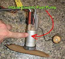
As engines moved away from carburetors and towards fuel injection, mechanical fuel pumps were replaced with electric fuel pumps, because fuel injection systems operate more efficiently at higher fuel pressures (40–60 psi) than mechanical diaphragm pumps can generate. Electric fuel pumps are generally located in the fuel tank, in order to use the fuel in the tank to cool the pump and to ensure a steady supply of fuel.
Another benefit of an in-tank mounted fuel pump is that a suction pump at the engine could suck in air through a (difficult to diagnose) faulty hose connection, while a leaking connection in a pressure line will show itself immediately. A potential hazard of a tank-mounted fuel pump is that all of the fuel lines are under (high) pressure, from the tank to the engine. Any leak will be easily detected, but is also hazardous.
Electric pump

In many modern cars the fuel pump is usually electric and located inside the fuel tank. The pump creates positive pressure in the fuel lines, pushing the gasoline to the engine. The higher gasoline pressure raises the boiling point. Placing the pump in the tank puts the component least likely to handle gasoline vapor well (the pump itself) farthest from the engine, submersed in cool liquid. Another benefit to placing the pump inside the tank is that it is less likely to start a fire. Though electrical components (such as a fuel pump) can spark and ignite fuel vapors, liquid fuel will not explode (see flammability limit) and therefore submerging the pump in the tank is one of the safest places to put it. In most cars, the fuel pump delivers a constant flow of gasoline to the engine; fuel not used is returned to the tank. This further reduces the chance of the fuel boiling, since it is never kept close to the hot engine for too long.
An advantage of an electric fuel pump is reduced fuel consumption because it does not have the resistance associated with a mechanical drive and because the fuel supply can be monitored more accurately by the electronic control unit (ECU). Pre-delivery of fuel can also be accomplished by an electric fuel pump because it does not depend on engine rpm. Due to this, rapid engine starting can be implemented to conserve gas. This is particularly important in stop-start systems where the engine turns itself off when it senses no use, such as stopped at a stoplight.
The ignition switch does not carry the power to the fuel pump; instead, it activates a relay which will handle the higher current load. It is common for the fuel pump relay to become oxidized and cease functioning; this is much more common than the actual fuel pump failing. Modern engines utilize solid-state control which allows the fuel pressure to be controlled via pulse-width modulation of the pump voltage. This increases the life of the pump, allows a smaller and lighter device to be used, and reduces electrical load.
Cars with electronic fuel injection have an electronic control unit (ECU) and this may be programmed with safety logic that will shut the electric fuel pump off, even if the engine is running. In the event of a collision this will prevent fuel leaking from any ruptured fuel line. Additionally, cars may have an inertia switch (usually located underneath the front passenger seat) that is "tripped" in the event of an impact, or a roll-over valve that will shut off the fuel pump in case the car rolls over.
Some ECUs may also be programmed to shut off the fuel pump if they detect low or zero oil pressure, for instance if the engine has suffered a terminal failure (with the subsequent risk of fire in the engine compartment).
The fuel sending unit assembly may be a combination of the electric fuel pump, the filter, the strainer, and the electronic device used to measure the amount of fuel in the tank via a float attached to a sensor which sends data to the dash-mounted fuel gauge. The fuel pump by itself is a relatively inexpensive part. But a mechanic at a garage might have a preference to install the entire unit assembly.
High-pressure Fuel Pumps
Pumps for direct-injection engines - such as diesel engines and direct-injection gasoline engines - operate at a much higher pressure due to the engine’s specs and are usually mechanical pumps such as common rail radial piston pump, common rail two piston radial, inline pump, port and helix, and metering unit design. Radial piston pumps used in cars and trucks are fuel lubricated, this helps with keeping oil out of the high pressure fuel. Oil in the fuel can raise emissions and clog injectors.[3] Many diesel engines are common rail, which means all the injectors are supplied by one pipe full of high pressure fuel supplied by the fuel pump. Common rails dampen the pressure fluctuations when fuel is used by each injector and pumped into the cylinder. Common rails also make it easier for the fuel pressure to be measured by one device instead of one per cylinder.[3] Port and Helix (plunger type) high pressure fuel pumps are most commonly used in marine diesels because of their simplicity, reliability, and its ability to be scaled up in proportion to the engine size.[2]
Port and Helix type pump
Port and Helix pumps are cam driven plunger type pumps that run at one-half engine rpm for four stoke engines and at the same rpm in the case of a two stroke. The pump is similar to that of a radial piston type pump but instead of a piston it has a machined plunger that has no seals. When the plunger is at top dead center, the injection to the cylinder is finished and it is returned on its downward stroke by a compression spring.[2] Because the height of the cam lobe cannot be easily changed, the amount of fuel being pumped to the injector is controlled by a rack and pinion device that rotates the plunger allowing variable amounts of fuel to the area above the plunger. Inlet and outlet ports are located on two sides of the pumps cylinder walls allowing fuel to flow through the compression chamber until the plunger is driven up closing the two ports and starting the compression motion. The outlet port feeds back into the fuel tank/settler of the engine. The fuel is then forced through a stop check valve, to prevent backflow to the injector nozzle at pressures that can exceed 18,000 psi.[3]
Turbopumps
Many jet engines, including rocket engines use a turbopump which is a centrifugal pump usually propelled by a gas turbine or in some cases a ram-air device (particularly in ramjet engines which lack a shaft).
References
| Wikimedia Commons has media related to Fuel pumps. |
- Hollembeak, Barry (2005). Classroom Manual for Automotive Fuels and Emissions. Cengage Learning. p. 154. Retrieved June 12, 2012.
- Judge, A. (1965). Modern Smaller Diesel Engines (Vol. 7). Cambridge, Massachusetts: Robert Bentley Inc.
- Mollenhauer, K., & Tschöke, H. (2010). Handbook of Diesel Engines. Berlin: Springer- Verlag.