IEC 60309
IEC 60309 (formerly IEC 309 and CEE 17, also published by CENELEC as EN 60309) is an international standard from the International Electrotechnical Commission (IEC) for "plugs, socket-outlets and couplers for industrial purposes". The maximum voltage allowed by the standard is 1000 V DC or AC; the maximum current, 800 A; and the maximum frequency, 500 Hz. The ambient temperature range is −25 °C to 40 °C.[1]
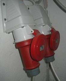
There is a range of plugs and sockets of different sizes with differing numbers of pins, depending on the current supplied and number of phases accommodated. The fittings are popular in open-air conditions, as they include IP44 weather-proofing. They are also sometimes used in situations where their special capabilities (such as high current rating or three-phase facilities) are not needed, to discourage potential users from connecting domestic appliances to the sockets, as 'normal' domestic plugs will not fit.
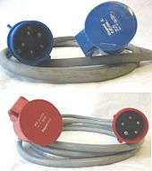
The cable connectors and sockets are keyed and colour-coded, according to the voltage range and frequency used; common colours for 50–60 Hz AC power are yellow for 100–130 volts, blue for 200–250 volts, and red for 380–480 volts. The blue fittings are often used for providing weather-proofed exterior sockets for outdoor apparatus. In camping situations, the large 32 A blue fittings provide power to static caravans, whilst the smaller blue 16 A version powers touring caravans and tents. The yellow fittings are used to provide transformer isolated 110 V supplies for UK construction sites to reduce the risk of electric shock, and this use spills over into uses of power tools outside of the construction site environment. The red three-phase versions are used for three-phase portable equipment.
Standardization

- IEC 60309-1
- "Plugs, socket-outlets and couplers for industrial purposes" specifies general functional and safety requirements.[2]
- IEC 60309-2
- "Dimensional interchangeability requirements for pin and contact-tube accessories" applies to plugs and socket-outlets, cable couplers and appliance couplers with pins and contact tubes of standardized configurations.
- IEC 60309-3
- "Particular requirements for plugs, socket-outlets, connectors and appliance inlets for use in explosive gas atmospheres" was withdrawn in 1998.
- IEC 60309-4
- "Switched socket-outlets and connectors with or without interlock" applies to self-contained products that combine within a single enclosure, a socket-outlet or connector according to IEC 60309-1 or IEC 60309-2 and a switching device, with a rated operating voltage not exceeding 1000 V DC or AC and 500 Hz, and a rated current not exceeding 800 A.
- IEC 60309-5
- "Dimensional compatibility and interchangeability requirements for plugs, socket-outlets, ship connectors and ship inlets for low-voltage shore connection systems (LVSC)" applies to a single type of plug, socket-outlet, ship connector and ship inlet, intended to connect ships to dedicated shore supply systems described in IEC/IEEE 80005-3.
The standardization was originally done by the CEE (Commission internationale de réglementation en vue de l'approbation de l'équipement électrique), which became IECEE in 1985 (International Commission on the Rules for the Approval of Electrical Equipment) and is now part of the IEC. (This is the same body that produced the "CEE 7" series of domestic AC plugs.) The industrial sockets were standardized in the 1960s in the CEE 17 series that was adopted in the UK as BS 4343, and which are now the IEC 60309 standard.[3]
Preferred current ratings and wire gauges
The standard includes preferred current ratings and wire gauges for both International (deemed Series I) and North American (deemed Series II) applications.
Series I preferred current ratings (in Amps) are: 16, 32, 63, 125, 250, 400, 630 and 800, with wire gauges specified as mm2.
Series II preferred current ratings (in Amps) are: 20, 30, 60, 100, 200, 300, 350, 500 and 600, with wire gauges specified as AWG and circular mil.
Environmental protection

IEC 60309 connectors come in IP44 (splash-proof) and IP67 (waterproof) variants. In both cases, the rating applies when detached or mated, but not during the mating process.
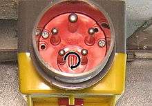
The more common IP44 variant features a spring-loaded hinged cap over the socket. When a plug is inserted, the cap hooks over a lug on the plug and retains it in place. Fixed connectors are usually installed angled downward to prevent water entering.
The IP67 variant includes a gasket and twist-lock ring which seals the two together.
The two can be intermated, at the cost of the locking mechanisms; they are only held by friction.
Dimensions

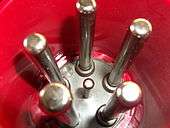
Plugs have cylindrical connector pins arranged in a circle, with the earth pin 2 mm larger than the others. This is surrounded by a circular shroud on the male connector, which fits into a matching recess on the female connector.
The standard defines connectors with 3, 4 and 5 pins, but a non-standard variant with 7 pins (6 in a circle plus one in the centre) is commercially available;[4] this can be used for star-delta starting of three-phase motors.
| Connector rating (A) | 16 | 32 | 63 | 125 | |||
|---|---|---|---|---|---|---|---|
| Pins | 2+E | 3+E | 4+E | 2+E, 3+E | 4+E | All | All |
| L/N pin diameter (mm) | 5 | 6 | 8 | 10 | |||
| L/N pin length (mm) | 37 | 45 | 67 | 71 | |||
| Earth pin diameter | 7 | 8 | 10 | 12 | |||
| Earth pin length (mm) | 37 | 45 | 67 | 71 | |||
| Pin circle diameter (mm) | 17.5 | 21.5 | 26.5 | 25.0 | 30.3 | 36.5 | 42.5 |
Pilot contact
Connectors rated at 63 A and 125 A may optionally be equipped with a 6 mm pilot contact. This smaller pin in the centre of the connector is shorter than the others, designed to 'make' after all the other pins when connecting a plug and socket, and to 'break' first when disconnecting. It is used to switch off the load. This is useful as disconnecting under load will cause arcing which may cause damage to both the plug and socket, and risk injury to the user.
The pilot pin is located in the centre of main contact circle on 4- and 5-pin connectors. On 3-pin (2P+E) connectors, it is located on the contact circle opposite the ground pin. The other connectors are located 105° on either side of the earth pin, rather than 120° as in the smaller variants, to make room for the pilot pin.
Extra-low voltage variant

The standard specifies an additional, different design for extra-low voltages up to 50 V AC and currents of 16 or 32 A. This resembles, but is larger than, the IEC 60906 DC connector. Three 6 mm pins 20.5 mm long are equally spaced around a 15.4 mm diameter circle. They are surrounded by a 23 mm long shroud with an inner diameter of 36 mm and an outer diameter of 42 mm.
Keying is done by one or two keys on the inside of the socket, which fit into grooves provided on the outside of the plug's shroud. The major keyway is 4 mm deep, and there is a corresponding flat protruding into the interior of the shroud to accommodate it. The width of the major keyway defines the current rating: 32 A plugs have a 5 mm wide groove, while 16 A plugs have an 8 mm groove, and will therefore fit into 32 A sockets but not vice versa.
Instead of a distinguished earth pin, an optional minor key is an additional 5 mm wide groove cut through the shroud. The pin opposite the major key is also optional and may be omitted to make a 2-pin variant.
Colour code
The colour of the housing indicates the type of power available. The primary distinction is by rated operating voltage, as follows:
- 20–25 V: Violet
- 40–50 V: White
- 100–130V: Yellow
- 200–250 V: Blue
- 380–480 V: Red
- 500–1000 V: Black
Commonly used colours are yellow (125 V), blue (250 V), and red (400 V). The black version (500 V) can often be found on ships.
In addition to the above:
- Green is used (possibly in combination with another colour) for AC frequencies higher than 60 Hz nominal, such as 400 Hz aircraft power,
- Orange is reserved for Series II current ratings at 125/250 V
- Grey is reserved for Series II current ratings at 277 V single-phase AC power.
Keying
In addition to the colour code, connectors are keyed in one of 12 positions to ensure that incompatible utilization voltages cannot be connected. Different voltage and frequency combinations are distinguished by the location of the earth pin (or a plastic projection called the minor keyway, for connectors with no earth pin), as shown in the following table. The earth pin can be in one of twelve locations, described by clock positions 1h through 12h, spaced at 30° intervals around the circle on which all the pins lie. The various positions are referenced from the view of the open side of a socket; the 6 o'clock (6h, 180°) position is at the same angle as the major keyway, and is oriented downwards. The major keyway is a projection on the plug shroud which aligns with a notch on the socket. The earth pin has a larger diameter than the other pins, preventing the wrong type of plug being inserted in a socket.
The extra-low voltage connector also supports keying, although in this case the angle is the position of the minor key relative to the major key. Minor key positions 5h, 6h and 7h are unavailable, as they would overlap with the major key, but an unkeyed variant exists.
| Earth pin position |
Pin configuration (P: pole, N: neutral, E: earth/ground) | ||
|---|---|---|---|
| P+N+E, 2P+E | 3P+E | 3P+N+E | |
| 30° / 1h | Not standardized, reserved for special purposes | ||
| 60° / 2h | >50 V 300–500 Hz (green) | >50 V 300–500 Hz (green) | >50 V 300–500 Hz (green) |
| 90° / 3h | 50–250 V DC (white) | 380 V 50 Hz (red) 440 V 60 Hz (red) |
220/380 V 50 Hz (red) 250/440 V 60 Hz (red) |
| 120° / 4h | 100–130 V AC (yellow) | 100–130 V AC (yellow) or in UK 55/110 split phase (2P+N+E) |
57–75/100–130 V AC (yellow) |
| 150° / 5h | 277 V 60 Hz (grey) | 600–690 V AC (black) | 347–400/600–690 V AC (black) |
| 180° / 6h | 200–250 V AC (blue) | 380–415 V AC (red) | 200–240/346–415 V AC (red) |
| 210° / 7h | 480–500 V AC (black) | 480–500 V AC (black) | 277–288/480–500 V AC (black) |
| 240° / 8h | >250 V DC (white) | ||
| 270° / 9h | 380–415 V AC (red) | 200–250 V AC (blue) | 120–144/208–250 V AC (blue) |
| 300° / 10h | >50 V, 100–300 Hz (green) | ||
| 330° / 11h | 440–460 V 60 Hz (red) | 250–265/440—460 V 60 Hz, (red) | |
| 360° / 12h | 125/250 V 60 Hz split phase (2P+N+E) (orange) |
||
| Characteristic | Colour | Earth pin (o'clock) | Note(s) |
|---|---|---|---|
| 100–130 V | Yellow | 4 | [note 1] |
| 120/240 V | Orange | 12 | [note 2][note 3] |
| 200–250 V | Blue | 6 | [note 4] |
| 120–250 V | Blue | 9 | [note 5] |
| 50–250 V DC | White | 3 | |
| >250 V DC | White | 8 | |
| 277 V 60 Hz only | Grey | 5 | [note 4][note 2] |
| 380 V 50 Hz only | Red | 3 | [note 5][note 6] |
| 380–480 V | Red | 6 | [note 5] |
| 380–480 V | Red | 11 | [note 7] |
| 380–415 V | Red | 9 | [note 4] |
| 440 V 60 Hz only | Red | 3 | [note 5][note 6] |
| 480–500 V | Black | 7 | [note 5] |
| 500–1000 V | Black | 5 | [note 5] |
| 100–300 Hz | Green | 10 | [note 8][note 6] |
| 300–500 Hz | Green | 2 | [note 9][note 6] |
- Notes
- ↑ Single phase voltage or three phase line voltage (phase-phase) including supplies from an isolating transformer.
- 1 2 For countries only where Series II current ratings (20, 30, 60, 100 amps) are used.
- ↑ North American 120/240 V single-phase system. Four pin (2P+N+E) connector only.
- 1 2 3 Single phase.
- 1 2 3 4 5 6 Three phase line voltage (phase-phase).
- 1 2 3 4 Only available in 16 and 32 Amp sizes.
- ↑ Three phase line voltage (phase-phase) at 60 Hz only.
- ↑ Greater than 50 volts three phase line voltage (phase-phase). Not available in single phase version.
- ↑ Greater than 50 volts single phase or three phase line voltage (phase-phase).
- All AC systems are either 50 or 60 Hz unless otherwise stated.
- All three phase plugs and socket are available in 3P+E or 3P+N+E (but see Note 7).
Common plugs
Red 3P+N+E, 6h
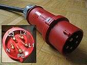
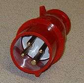
The red 3P+N+E, 6h (180°) plug allows connecting to the widespread 400 V three phase power network. The most common ratings are 16 A, 32 A and 63 A, with 125 A less common. Construction sites in central Europe have most of their higher power cabling setup with this three phase socket type as the single phase to neutral voltage of 230 V is available for other devices. So called power splitters with this connector as a 3 phase inlet and 3 groups of single phase outputs with individual circuit breakers are generally used to achieve this, and allow load balancing across the phases, important on generator supplies. Similar configurations are used for outdoor exhibitions, festivals and large events.
When looking at the socket, the phase sequence should be L1, L2, L3, and then the neutral pin, proceeding clockwise from the earth pin. (Counter-clockwise on the corresponding plug.) Since some wiring may be reversed, which would make motors turn backward, many machines on construction sites feature a phase swap plug that allows the L2 and L3 phase pins to be swapped, thereby reversing the phase sequence.
Three-phase electric motors do not need the neutral wire to function, so that there is also a red four pin variant (3 phases and earth) of the IEC 60309 plugs for three phase power. The two styles are not intermatable, to prevent a potential floating neutral.
Blue P+N+E, 6h

The blue P+N+E, 6h (180°) plug is a single phase connector. In particular the smallest (16 A) variant has become especially common in camping vehicles and sockets found in caravan parks and marinas throughout Europe. The so-called 'Caravan Mains Socket' has almost universally replaced a wide variety of other national 230 V domestic plugs since it is pan-European and inherently safe to standard IP44. On larger temporary buildings, particularly with electric heating the larger 32 A is more common.
The pins are specified to be in the order earth, phase, and neutral, clockwise when looking at the socket. Not all installations distinguish the live (phase) and neutral conductors, and reverse wired sockets are quite common, so double pole breaking RCDs and main switches are recommended. When sockets are mounted looking downwards then the connector system is rated for outdoor use in all weather. This is also the standard connector for lighting equipment (up to 16 A) used in the British film and television industry (often as outlets from a power splitter with a higher rated 3 phase input).
Yellow P+N+E, 4h
The yellow P+N+E, 4h (120°) plug is a single phase connector that is in widespread use on the British Isles for 110 V building site and fairground applications. A popular model of this socket type is marketed under the brand name MK Commando[6] which leads some users to refer to all IEC 60309 sockets by the generic trademark Commando sockets.
Blue 3P+N+E, 9h
The blue 3P+N+E, 9h (270°) plug is a three phase connector available in areas with both 115 V and 230 V supply systems (mains). It is prevalent in the outdoor event lighting and audio power industry as an outdoor-safe replacement for NEMA connectors. In the United States it is not usually used for three phase power but for the high leg delta wiring of split-phase electric power (unknown in Europe). This allows one to choose single-phase AC power at either 110–120 volts between phase and neutral or 220–240 volts between phase and phase. Since these two modes do not need three phases there is also a dark yellow-orange four-pin connector available designed for a single-phase 110–120 or 220–240-volt load.
It is best to connect the high leg adjacent to the earth pin, so that it will not be misplaced by phase-swap plugs.
See also
| Wikimedia Commons has media related to IEC 60309. |
- Industrial and multiphase power plugs and sockets
- IEC 62196 for electric vehicles
- Perilex, obsolescent DIN connector
- NEMA connector
- IEC 60906-3 a series of smaller 16 A low-voltage connectors with a superficially similar appearance
References
- ↑ Scope section 1, IEC 60309-1:1999+AMD1:2005+AMD2:2012 Part 1 General Requirements, 2012, International Electrotechnical Commission
- ↑ BS EN 60309-1, IEC 60309-1: "Plugs, socket-outlets and couplers for industrial purposes. General requirements." (1999/2012)
- ↑ "General Introduction of CEE plugs and receptacles". Rey & Lenferna. MENNEKES industrial plugs and receptacles. Retrieved 2011-09-03.
History: CEE plugs and sockets base on the CEE 17 standard (also BS 4343) which was introduced in the 1960s.
- ↑ "Industrial Plugs and Sockets to IEC 60309-2 (BS4343/CEE17) trade price list" (PDF). Walther Electrotechnische systeme. 2012. Retrieved 2017-03-26.
- ↑ "The IEC 60309 "Clock"". ABB Group. 18 November 2008. Retrieved 2017-03-27.
- ↑ "Commando Plugs and Sockets". MK Electric. Retrieved 2017-03-26.
External links
- IEC 60309-1 Plugs, socket-outlets and couplers for industrial purposes - Part 1: General requirements
- IEC 60309-2 Plugs, socket-outlets and couplers for industrial purposes - Part 2: Dimensional interchangeability requirements for pin and contact-tube accessories
- IEC 60309-4 Plugs, socket-outlets and couplers for industrial purposes - Part 4: Switched socket-outlets and connectors with or without interlock
- "IEC 60309" at International Electrotechnical Commission