IEC 62196
IEC 62196 Plugs, socket-outlets, vehicle connectors and vehicle inlets – Conductive charging of electric vehicles, also known as CCS Combo, is a series of international standards that define requirements and tests for plugs, socket-outlets, vehicle connectors and vehicle inlets for conductive charging of electric vehicles and is maintained by the technical subcommittee SC 23H “Plugs, Socket-outlets and Couplers for industrial and similar applications, and for Electric Vehicles” of the International Electrotechnical Commission (IEC).
Plugs, socket-outlets, vehicle connectors and vehicle inlets according to this series of standards are used in EV supply equipment according to IEC 61851 series or IEC 62752 and in electric vehicles according to ISO 17409 or ISO 18246.
Most plugs, socket-outlets, vehicle connectors and vehicle inlets according to this series of standards provide additional contacts that support specific functions that are relevant for charging of electric vehicles, e.g. power is not supplied unless a vehicle is connected and the vehicle is immobilized while still connected.
Several parts of this series of standards have been published as European standards (EN 62196 series) which in turn have been published as British standards (BS EN 62196 series). Similar requirements are contained in SAE J1772 which is widely applied in the US.
Parts
The following parts of IEC 62196 series have been published:
- IEC 62196-1 Plugs, socket-outlets, vehicle connectors and vehicle inlets – Conductive charging of electric vehicles – Part 1: General requirements
- IEC 62196-2 Plugs, socket-outlets, vehicle connectors and vehicle inlets – Conductive charging of electric vehicles – Part 2: Dimensional compatibility and interchangeability requirements for A.C. pin and contact-tube accessories
- IEC 62196-3 Plugs, socket-outlets, vehicle connectors and vehicle inlets – Conductive charging of electric vehicles – Part 3: Dimensional compatibility and interchangeability requirements for D.C. and A.C./D.C. pin and contact-tube vehicle couplers
Additional parts of IEC 62196 are under preparation (as of July 2018):
- IEC TS 62196-3-1 Plugs, socket-outlets, vehicle connectors and vehicle inlets – Conductive charging of electric vehicles – Part 3-1: Vehicle connector, vehicle inlet and cable assembly intended to be used with a thermal management system for DC charging
- IEC TS 62196-4 Plugs, socket-outlets, vehicle connectors and vehicles inlet – Conductive charging of electric vehicles – Part 4: Dimensional compatibility and interchangeability requirements for DC pin and contact-tube accessories for class II or class III applications
- IEC 62196-6 Plugs, socket-outlets, vehicle connectors and vehicle inlets – Conductive charging of electric vehicles – Part 6: Dimensional compatibility and interchangeability requirements for DC pin and contact-tube vehicle couplers for DC EV supply equipment where protection relies on electrical separation
IEC 62196-1
Contents
IEC 62196-1 provides a general description of the interface between an electric vehicle and a charging station as well as general mechanical and electrical requirements and tests for plugs, socket-outlets, vehicle connectors and vehicle inlets that are intended to be used for EV charging. It does not describe specific designs, which can be found in the other parts of the standard.
History
The first edition, IEC 62196-1:2003, was published in 2003. This edition was applicable to plugs, socket-outlets, connectors, inlets and cable assemblies for AC and DC charging of electric vehicles with rated voltages and rated currents as follows:
- AC: up to 690 V, up to 250 A
- DC: up to 600 V, up to 400 A.
Typical connectors and inlets that were built according to this edition of the standard used spring-loaded butt contacts and were made by Avcon and Maréchal Electric.
The second edition, IEC 62196-1:2011, was published in 2011. One significant change was the increase of the maximum voltage of connectors, inlets and cable assemblies for DC charging to 1500 V. The development of this edition was coordinated with the first edition of IEC 62196-2, which describes several configurations of pin-and-sleeve contacts for AC charging.
The third edition, IEC 62196-1:2014, was published in 2014. One significant addition was the general description of a “combined interface” as used by the Combined Charging System. The development of this edition was coordinated with the first edition of IEC 62196-3, which describes connectors and inlets for DC charging.
IEC 62196-2
Contents
IEC 62196-2 extends IEC 62196-1 and describes specific designs of plugs, socket-outlets, vehicle connectors and vehicle inlets that are intended to be used for AC charging of electric vehicles in the modes 1, 2 and 3 as described by IEC 61851-1. The specific designs are grouped into three configurations.
The designs are described with sufficient detail to allow compatibility between products of different manufacturers.
Configurations
Type 1

This configuration consists of a vehicle coupler (vehicle connector and vehicle inlet).
Because the original design was made by the manufacturer Yazaki and first published in SAE J1772, it is colloquially known as the “Yazaki connector” or “J1772 connector”.
It features a round housing, which has a notch on the vehicle inlet for proper orientation, with five pin-and-sleeve contacts for two AC conductors, a protective conductor and two signal pins that are used for the control pilot function (according to IEC 61851-1 Annex A) and for proximity detection (using an auxiliary switch and no current coding, according to IEC 61851-1 Annex B). When inserted into the vehicle inlet, the connector is held in place by a mechanical latch, which is part of the connector.
IEC 62196-2 describes this configuration with an operating current up to 32 A, allowing a maximum current of 80 A only for applications in the US, where this higher operating current is also described by SAE J1772.
This configuration only supports single-phase charging. It is widely used in the US and Japan.
Type 2
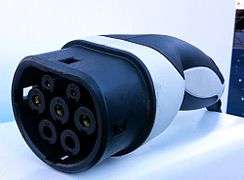
This configuration consists of a plug and socket-outlet that support charging in mode 3, as described in IEC 61851-1, and a vehicle coupler, consisting of vehicle connector and vehicle inlet, that supports charging in modes 2 and 3. (Within this configuration, IEC 62196-2 additionally describes a connector for mode 1 and an inlet for all modes 1, 2 and 3, but these are not used.)
Because the original design was made by the manufacturer Mennekes, it is colloquially known as the “Mennekes connector”.
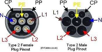
It features a round housing, which is flattened on one side for proper orientation, with up to seven pin-and-sleeve contacts for up to four AC conductors, a protective conductor and two signal pins that are used for the control pilot function (according to IEC 61851-1 Annex A) and for simultaneous proximity detection and current coding (according to IEC 61851-1 Annex B). By design, the contacts can not be touched by the standardized test finger. Since the second edition of the standard, additional touch protection of the contacts can optionally be provided by shutters. When inserted into the inlet, the connector is held in place by the locking mechanism, which is attached to the inlet. The same concept is used by the socket-outlet to hold the plug in place.
IEC 62196-2 describes this configuration with operating currents up to 63 A, allowing a maximum current of 70 A only for single-phase applications.
Configuration type 2 differs from the first proposal by Mennekes that was presented in the German standard VDE-AR-E 2623-2-2 that was published in 2009 and withdrawn in 2012, when the German version of IEC 62196-2:2011 became available. Pins and sleeves were swapped between the inlet and the connector and the dimensions were slightly changed.
Another similar but different design is described by the Chinese standard GB/T 20234.2.
Within the European Union, regulation requires all public AC charging stations to be equipped with a type 2 socket-outlet or a type 2 connector.
Type 3
This configuration consists of three groups each comprising a plug, a socket-outlet and a vehicle coupler (vehicle connector and vehicle inlet).
Because the original design was made by the manufacturer Scame, it is colloquially known as the “Scame connector”.
It features an oval housing, which is flattened on one side for proper orientation, with up to seven pin-and-sleeve contacts for up to four AC conductors, a protective conductor and one or two signal pins that are used for simultaneous proximity detection and current coding (according to IEC 61851-1 Annex B) and, where present, for the control pilot function (according to IEC 61851-1 Annex A). Touch protection of the contacts is provided by shutters. When inserted into the vehicle inlet, the connector is held in place by the locking mechanism, which is attached to the vehicle inlet. The same concept is used by the socket-outlet to hold the plug in place.
IEC 62196-2 describes three different designs with different dimensions under this configuration that support:
- single-phase charging at up to 16 A, without control pilot contact,
- single-phase charging at up to 32 A,
- three-phase charging at up to 63 A.
History
The first edition, IEC 62196-2:2011, was published in 2011.
The second edition, IEC 62196-2:2016, was published in 2016. The most significant change was the introduction of optional shutters for configuration type 2.
IEC 62196-3
Contents
IEC 62196-3 extends IEC 62196-1 and describes specific designs of vehicle connectors and vehicle inlets that are intended to be used for DC charging of electric vehicles in mode 4 as described by IEC 61851-1 and IEC 61851-23. The specific designs are grouped into several configurations.
The designs are described with sufficient detail to allow compatibility between products of different manufacturers.
The first edition, IEC 62196-3:2014, was published in 2014.
Configurations
All configurations consist of a connector and inlet.
Configurations with the letters DD and EE were discussed during the work on the document but are not specified in the published version of IEC 62196-3:2014.
AA
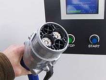
Configuration AA is colloquially known as the “Chademo connector”, because it was designed and is used by the Chademo organisation. The original design was first published in the Japanese standard JEVS G105-1993.
This coupler is intended to be used with DC charging stations that implement System A according to IEC 61851-23 and CAN-communication according to IEC 61851-24 Annex A. It is mostly used in Japan and in countries with many electric vehicles that were designed in Japan.
BB
Configuration BB is intended to be used with DC charging stations that implement System B according to IEC 61851-23 and CAN communication according to IEC 61851-24 Annex B. It is mostly used in China, where the same technical solution is described by the standard GB/T 20234.3.
CC
Configuration CC is colloquially known as the “CCS1 connector” or “Combo1 connector”, because it is used within the Combined Charging System and extends the type 1 coupler.
Configuration CC is intended to be used with DC charging stations that implement System C according to IEC 61851-23 and PLC communication according to IEC 61851-24 Annex C and ISO 15118-3. It is mostly used in the US, where the same technical solution is described by the standard SAE J1772.

FF
Configuration FF is colloquially known as the “CCS2 connector” or “Combo2 connector”, because it is used within the Combined Charging System and extends the type 2 coupler.
Configuration FF is intended to be used with DC charging stations that implement System C according to IEC 61851-23 and PLC communication according to IEC 61851-24 Annex C and ISO 15118-3. It is mostly used in Europe. Within the European Union, regulation requires all public DC charging stations to be equipped with a configuration FF connector.
IEC TS 62196-3-1
This IEC technical specification will describe how vehicle connectors and vehicle inlets according to IEC 62196-3 can be used with cables with quite small conductor cross section if thermal management is applied. Thermal management uses thermal sensors and adjusts the current to limit the temperature rise of the cable assembly. This document is under preparation (as of July 2018) and the final version has not yet been published.
IEC TS 62196-4
This IEC technical specification extends IEC 62196-1 and describes specific designs of plugs, socket-outlets, vehicle connectors and vehicle inlets that are intended to be used for DC charging through circuits specified in IEC 61851-3 series. The maximum operating voltage is 120 V at a nominal current of up to 60 A. One typical application are light electric vehicles.
Preparation of this document is finished (as of July 2018) but the final version has not yet been published.
IEC 62196-6
This IEC technical specification will extend IEC 62196-1 and describe specific designs of plugs, socket-outlets, vehicle connectors and vehicle inlets that are intended to be used for DC charging through circuits that will be specified in IEC 61851-23-2. The maximum operating voltage is 120 V at a nominal current of up to 100 A. One typical application will be light electric vehicles.
This document is under preparation (as of July 2018) and the final version has not yet been published.
See also
References
- IEC 62196-1:2003
- IEC 62196-1:2011
- IEC 62196-1:2014
- IEC 62196-2:2011
- IEC 62196-2:2016
- IEC 62196-3:2014
- SC 23H Work programme
- Directive 2014/94/EU of the European Parliament and of the Council of 22 October 2014 on the deployment of alternative fuels infrastructure