Helios (spacecraft)
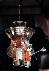
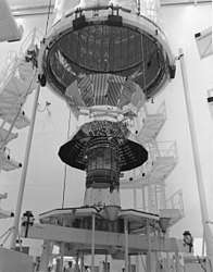 Prototype of the Helios spacecraft | |
| Mission type | Solar observation |
|---|---|
| Operator | NASA · DFVLR |
| COSPAR ID |
Helios-A: 1974-097A Helios-B: 1976-003A |
| SATCAT no. |
Helios-A: 7567 Helios-B: 8582 |
| Website |
Helios-A: Solar System Exploration Helios-B: Solar System Exploration |
| Mission duration |
Helios-A: 10 years, 1 month, 2 days Helios-B: 3 years, 5 months, 2 days |
| Spacecraft properties | |
| Manufacturer | MBB |
| Launch mass |
Helios-A: 371.2 kg (818 lb) Helios-B: 374 kg (825 lb) |
| Power | 270 watts (solar array) |
| Start of mission | |
| Launch date |
Helios-A: December 10, 1974, 07:11:01 UTC[1] Helios-B: January 15, 1976, 05:34:00 UTC[2] |
| Rocket | Titan IIIE / Centaur |
| Launch site | Cape Canaveral SLC-41 |
| Entered service |
Helios-A: January 16, 1975 Helios-B: July 21, 1976 |
| End of mission | |
| Deactivated |
Helios-A: February 18, 1985 Helios-B: December 23, 1979 |
| Last contact |
Helios-A: February 10, 1986 Helios-B: March 3, 1980 |
| Orbital parameters | |
| Reference system | Heliocentric |
| Eccentricity |
Helios-A: 0.5218 Helios-B: 0.5456 |
| Perihelion |
Helios-A: 0.31 AU Helios-B: 0.29 AU |
| Aphelion |
Helios-A: 0.99 AU Helios-B: 0.98 AU |
| Inclination |
Helios-A: 0.02° Helios-B: 0° |
| Period |
Helios-A: 190.15 days Helios-B: 185.6 days |
| Epoch |
Helios-A: January 15, 1975, 19:00 UTC[1] Helios-B: July 20, 1976, 20:00 UTC[2] |
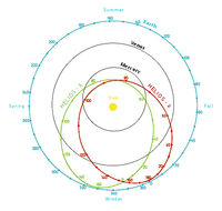
Helios-A and Helios-B (also known as Helios 1 and Helios 2), are a pair of probes launched into heliocentric orbit for the purpose of studying solar processes. A joint venture of West Germany's space agency DFVLR (70 percent share) and NASA (30 percent), the probes were launched from Cape Canaveral Air Force Station, Florida, on December 10, 1974, and January 15, 1976, respectively. Built by the main contractor Messerschmitt-Bölkow-Blohm, they were the first spaceprobes built outside both the United States and the Soviet Union to leave Earth orbit.
The probes set a maximum speed record for spacecraft of 157,078 mph (70,220 m/s).[3] Helios-B flew 3,000,000 kilometres (1,900,000 mi) closer to the Sun than Helios-A, achieving perihelion on April 17, 1976, at a record distance of 43.432 million km (26,987,000 mi; 0.29032 AU),[4] closer than the orbit of Mercury. Helios-B was sent into orbit 13 months after the launch of Helios-A. The Helios space probes completed their primary missions by the early 1980s, and continued to send data up to 1985.
The probes are no longer functional but remain in their elliptical orbits around the Sun.[5][6][7][8]
Structure
The two Helios probes look very similar. Helios-A has a mass of 370 kilograms (820 lb), and Helios-B has a mass of 376.5 kilograms (830 lb). Their scientific payloads, consisting of eight instruments, have a mass of 73.2 kilograms (161 lb) on Helios-A and 76.5 kilograms (169 lb) on Helios-B. The central body is a sixteen-sided prism 1.75 metres (5 ft 9 in) in diameter and 0.55 metres (1 ft 10 in) high. Most of the equipment and instrumentation is mounted in this central body. The exceptions are the masts and antennae used during experiments and small telescopes that measure the zodiacal light and which emerge from the central body. Two conical solar panels extend above and below the central body, giving the assembly the appearance of a diabolo or spool of thread.
At launch, each probe was 2.12 metres (6 ft 11 in) tall with a maximum diameter of 2.77 metres (9 ft 1 in). Once in orbit, a telecommunications antenna unfolded on top of the probe and increased the total height to 4.2 metres (14 ft). Also deployed on orbit were two rigid booms carrying sensors and magnetometers, attached on both sides of the central body, and two flexible antennae used for the detection of radio waves, which extended perpendicular to the axis of the spacecraft for a design length of 16 metres (52 ft) each.[9]
The spacecraft spins around its axis, which is perpendicular to the ecliptic, at 60 rpm.
Power
Electrical power is provided by solar cells attached to the two truncated cones. To keep the solar panels at a temperature below 165 °C (329 °F) in the proximity of the Sun, the solar cells are interspersed with mirrors, covering 50% of the surface and reflecting part of the incident sunlight while dissipating the excess heat. The energy supplied by the solar panels is a minimum of 240 watts when the probe is in the farthest part of its orbit from the Sun. The power whose voltage is regulated to 28 volts DC is stored on a silver–zinc battery of 8 Ah.
Thermal control

The biggest technical challenge faced by the designers was the heat to which the probe is subject when it is near the Sun. At 0.3 astronomical units (45,000,000 km; 28,000,000 mi) from the Sun, approximate heat flow is 11 solar constants (11 times the amount of received heat in Earth orbit), or 22.4 kW per square meter exposed. Under these conditions, the temperature of the probe can then reach 370 °C (698 °F). The solar cells and the central compartment of instruments must be maintained at much lower temperatures. The temperature of the solar cells should not exceed 165 °C (329 °F), while the central compartment should be maintained between −10 and 20 °C (14 and 68 °F). These restrictions require the rejection of 96 percent of the heat received from the Sun. The conical shape of the solar panels is one of the measures taken to reduce the flow of heat. By tilting the solar panels with respect to sunlight arriving perpendicularly to the axis of the probe, a greater proportion of the solar radiation is reflected. Furthermore, "second surface mirrors" specially developed by NASA cover the entire central body and 50 percent of the solar generators. These are made of fused quartz, with a silver film on the inner face, which is itself covered with a dielectric material. For additional protection, multi-layer insulation, consisting of 18 layers of 0.25 millimetres (0.0098 in) Mylar or Kapton (depending on location) held apart from each other by small plastic pins intended to prevent the formation of thermal bridges, was used to partially cover the core compartment. In addition to these passive devices, the probe uses an active system of movable louvers arranged in a shutter-like pattern along the bottom and top side of the compartment. The opening thereof is controlled separately by a bimetal spring whose length varies with temperature and causes the opening or closing of the shutter. Resistors are also used to maintain a temperature sufficient for certain equipment.[10]
Telecommunications system
The telecommunication system uses a radio transceiver, whose power can be adjusted between 0.5 and 20 watts. Three antennas are overlaid on top of the probe: A large antenna gain (23 dB) emits a top brush of 5.5° on either side of elliptical and 14° wide, a medium antenna gain (3 dB for the transmission and reception of 6.3 dB) emits a signal in all directions of the ecliptic plane at a height of 15° and a dipole omnidirectional antenna (0.3 dB in the transmission and – reception 0.8 db). The low gain horn antenna is located under the center of the probe because of an adapter that connected the probe to the launch vehicle. To be constantly pointed toward Earth, the biggest gain antenna is kept in rotation by a motor at a speed that counterbalances exactly the body of the probe. Synchronizing the speed is performed using data supplied by a Sun sensor. The maximum flow rate obtained with the large antenna gain is 4096 bits per second upstream. The reception and transmission of signals are supported by the Deep Space Network network antennas on Earth.
Attitude control
To maintain its orientation during the mission, the spacecraft rotates continuously at 60 rpm around its main axis. The orientation control system eventually makes corrections to the speed and orientation of the probe shaft. To determine its orientation using a rude Sun sensor, a Sun sensor and the end of a star seen that latch to the star Canopus. Guidance corrections are performed using cold gas thrusters 3 (7.7 kg nitrogen) with a boost of 1 Newton. The axis of the probe is permanently maintained, both perpendicular to the direction of the Sun and perpendicular to the ecliptic plane.
Board computer and data storage
The on-board controller is capable of handling 256 commands. The mass memory can store 500 kb and is mainly used when the probe is in superior conjunction relative to the Earth (i.e. the Sun comes between the Earth and the spacecraft). The conjunction may last up to 65 days. This was a very large memory for space probes of the time.
Scientific instrumentation
Both Helios probes had ten scientific instruments:[11]
- Plasma Experiment Investigation: developed by Max Planck Institute study of low-energy particles with three types of sensors: an analyzer proton and alpha particles when it is between 231 eV and 16 keV, a detector for protons and heavy particles and an electron detector. The instrument identifies all significant solar wind parameters: density, speed, temperature. Measurements are taken every minute, but 1/10 s to the flux density to highlight irregularities and plasma waves.
- Flux-gate Magnetometer: developed by the University of Braunschweig, Germany measuring three vector components of the magnetic field. The intensity is measured with an accuracy of 0.4 nT when below 102.4 nT to 1.2 nT at a lower intensity than 409.6 nT. Two sample rates are available: search every 2 seconds, or 8 readings per second.
- Flux-gate Magnetometer 2: developed by the Goddard Space Flight Center of NASA, with an accuracy of 0.1 nT about 25 nT to 0.3 nT about 75 nT to 0.9 nT at an intensity of 225 nT.
- Search Coil Magnetometer: developed by the University of Braunschweig as fluctuations in the magnetic field at 5 Hz frequency range–3 kHz. The spectral resolution is performed on the probe's rotation axis.
- Plasma Wave Investigation: developed by the University of Iowa studied electrostatic and electromagnetic waves in the frequencies between 10 Hz and 2 MHz.
- Cosmic Radiation Investigation: developed by the University of Kiel uses a detector semiconductor, one scintillator and Cherenkov counter encapsulated in an anti-coincidence detector to determine the intensity, direction and energy of the protons and heavy constituent particles this radiation.
- Low-Energy Electron and Ion Spectrometer: developed at Goddard Space Flight Center uses three telescopes to measure particle characteristics protons with energies between 0.1 and 800 MeV and electrons with an energy between 0.05 and 5 MeV. A detector is also studying the X-rays from the Sun. The three telescopes are installed to cover the ecliptic plane.[12]
- Zodiacal Light Photometer: counts the number of electrons and energy. Instrument's field of view is 20°, and can process stream comprising from 1 to 104 electrons per square centimeter. Three photometers developed by the Centre Heidelberg measure the intensity and polarization of the zodiac light in white light and in wavelength bands at 550 nm and 400 nm bands, using three telescope whose optical axis forms an angle of 15, 30 and 90 deg. to the ecliptic. From these observations information is obtained about the spatial distribution of interplanetary dust and the size and nature of the dust particles.
- Micrometeoroid Analyser: developed by Max Planck Institute can detect if the mass is greater than 10−15 g to determine the mass and energy of 10−14 g and in some cases the composition from 10−13 g. These measurements are made by taking advantage of the fact that micrometeorites hit a target vaporize and ionize. The instrument separates the ions and electrons in the plasma generated, measure the electric charge and deducts the mass and energy of the incident particle. A small mass spectrometer determines the composition of small ions.
- Celestial Mechanic Experiment: developed by University of Hamburg uses the Helios orbit specifics to clarify some astronomical measurements: flattening of the Sun, verification of the effects predicted by the theory of general relativity in orbit and spread the radio signal, improving the anniversary of the inner planets, planet Mercury mass, mass ratio of the Earth–Moon, integrated electron density between the ship and the ground station.
- Faraday Effect Experiment: developed by University of Bonn, operates this physical phenomenon affecting electromagnetic waves that pass through the corona to determine the density of electrons and the intensity of the magnetic field in the space region.
Mission
Helios-A
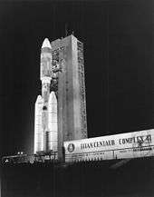
Helios-A was launched on December 10, 1974, from Cape Canaveral Air Force Station Launch Complex 41 in Cape Canaveral, Florida. This was the first operational flight of the Titan IIIE rocket. The rocket's test flight had failed when the engine on the upper Centaur stage did not light, but the launch of Helios-A was uneventful.
The probe was placed in a heliocentric orbit of 192 days with a perihelion of 46,500,000 km (28,900,000 mi; 0.311 AU) from the Sun. Several problems affected operations. One of the two antennas did not deploy correctly, reducing the sensitivity of the radio plasma apparatus to low-frequency waves. When the high-gain antenna was connected, the mission team realized that their emissions interfered with the analyzer particles and the radio receiver. To reduce the interference, communications were carried out using reduced power, but this required using the large diameter terrestrial receivers already stretched by other space missions in progress.
During the first perihelion in late February 1975, the spacecraft came closer to the Sun than any previous spacecraft. The temperature of some components reached more than 100 °C (212 °F), while the solar panels reached 127 °C (261 °F), without affecting probe operations. During the second pass on September 21, however, temperatures reached 132 °C (270 °F), which affected the operation of certain instruments.
Helios-B
Before Helios-B was launched, some changes were made to this spacecraft based on the lessons learned from the operations of Helios-A. The small engines used for attitude control were improved. Changes were made to the implementation mechanism of the flexible antenna and high gain antenna emissions. The X-ray detectors were improved so that they could detect gamma ray bursts and be used in conjunction with Earth-orbiting satellites to triangulate the location of the bursts. Because temperatures on Helios-A were always more than 20 °C (36 °F) below the design maximum at perihelion, it was decided that Helios-B would orbit even closer to the Sun. The thermal insulation was enhanced so that the satellite could support 15 percent greater heat flux.
Tight schedule constraints pressed on the Helios-B launch in early 1976. Facilities damaged during the launch of the Viking 2 spacecraft in September 1975 had to be rehabilitated, while the Viking landing on Mars in summer 1976 would make unavailable the Deep Space Network antennas that Helios-B would need to conduct its perihelion science. Helios-B was launched on January 10, 1976, by a Titan IIIE rocket. The probe was placed in an orbit with a 187-day period and a perihelion of 43,500,000 km (27,000,000 mi; 0.291 AU). The orientation of Helios-B with respect to the ecliptic was reversed 180 degrees compared to Helios-A so that the micrometeorite detectors could have 360 degree coverage. On April 17, 1976, Helios-B made its closest pass of the Sun at a record heliocentric speed of 70 kilometres per second (250,000 km/h; 160,000 mph). The maximum recorded temperature was 20 °C (36 °F) higher than measured by Helios-A.
End of operations
The primary mission of each probe spanned 18 months, but they operated much longer. On March 3, 1980, four years after its launch, the radio transceiver on Helios-B failed. On January 7, 1981, a stop command was sent to prevent possible radio interference during future missions. Helios-A continued to function normally, but with the large-diameter DSN antennae not available, data was collected by small diameter antennae at a lower rate. By its 14th orbit, its degraded solar cells could no longer provide enough power for the simultaneous collection and transmission of data unless the probe was close to its perihelion. In 1984, the main and backup radio receivers failed, indicating that the high-gain antenna was no longer pointed towards Earth. The last telemetry data was received on February 10, 1986.
Results

Both probes collected important data about the processes that cause the solar wind and the acceleration of the particles that make up the interplanetary medium and cosmic rays. These observations were made over a ten-year period from solar minimum in 1976 to a solar maximum in the early 1980s.
The observation of the zodiacal light has established some of the dust properties interplanetary present between 0.1 AU and 1 AU from the Sun, as their spatial distribution, color and polarization. It has been established that the powder was more sensitive to gravitational forces and electromagnetic forces. The amount of dust was observed up to 10 times around the Earth. Heterogeneous distribution was generally expected due to the passage of comets, but observations have not confirmed this. The probe instruments detected dust near the Sun showing that, despite the sunshine is still present in distance 0.09 AU.
Helios also allowed to collect interesting data on comets, watching the passage of C/1975 V1 (West) in 1976, C/1978 H1 (Meir) in November 1978 and C/1979 Y1 (Bradfield) in February 1980. During the last probe, instruments observed a disturbance wind solar which translated later by a break in the comet's tail. The plasma analyzer showed that the acceleration phenomena of the high-speed solar wind were associated with the presence of coronal holes. This instrument also detected for the first time, the helium ions isolated in the solar wind. In 1981, during the peak of solar activity, the data collected by Helios-A short distance from the Sun helped complete visual observations of coronal mass ejections performed from the Earth's orbit. Data collected by magnetometers two probes Helios supplemented with interplanetary probes Pioneer and Voyager were used to determine the direction of the magnetic field at staggered distances from the Sun.
The radio and plasma wave detectors were used to detect radio explosions and shock waves associated with solar flares, usually during solar maximum. The cosmic ray detectors studied how the Sun and interplanetary medium influenced the spread of the same rays, of solar or galactic origin. The gradient of cosmic rays, as a function of distance from the Sun, was measured. These observations, combined with those made by Pioneer 11 between 1977 and 1980 on the outside of the solar system (12–23 AU from the Sun) produced good modeling of this gradient. The GRBs Helios-B detector identified 18 events during the first three years of operation of the instrument, whose source can, for some, be identified with the help of searches made by satellites orbiting the Earth. Some features of the inner solar corona were measured during occultations. For this purpose, either a radio signal was sent from the spacecraft to Earth or the ground station sent a signal that was returned by the probe. Changes in signal propagation resulting from the solar corona crossing provided information on density fluctuations.
Mission background
Scientific instruments
| Instrument name | Description |
|---|---|
| Measures the velocity and distribution of the solar wind plasma. | |
| Measures the field strength and direction of low frequency magnetic fields in the Sun's environment. | |
| Complements the Flux-Gate Magnetometer by measuring the magnetic fields between 0 and 3 kHz. | |
| Measures and analyzes waves of free ions and electrons in the solar wind plasma, 10 Hz to 3 MHz region. | |
| Measures protons, electrons and x-rays to determine the distribution of cosmic rays. | |
| Investigates the higher energy portion of the crossover region between the solar wind particles and the cosmic rays. | |
| Measures the scattering of sunlight by interplanetary dust particles. | |
| Investigates the composition, charge, mass, velocity and direction of interplanetary dust particles. |
Mission profile
Launch and trajectory
Timeline of travel
| Date | Event |
|---|---|
| Launch of Helios-A | |
| Launch of Helios-B | |
| Closest flyby of the Sun of any spacecraft, performed by Helios-B: 0.29 AU (43.432 million km) from the Sun[4] |
Current status
As of 2016, the probes are no longer functional, but still remain in their elliptical orbits around the Sun.[5][6][7][8]
See also
References
- 1 2 "Helios-A – Trajectory Details". National Space Science Data Center. NASA. Retrieved July 12, 2017.
- 1 2 "Helios-B – Trajectory Details". National Space Science Data Center. NASA. Retrieved July 12, 2017.
- ↑ Wilkinson, John (2012), New Eyes on the Sun: A Guide to Satellite Images and Amateur Observation, Astronomers' Universe Series, Springer, p. 37, ISBN 3-642-22838-0
- 1 2 Solar System Exploration: Missions: By Target: Our Solar System: Past: Helios 2
- 1 2 http://www.n2yo.com/database/?m=12&d=10&y=1974#results
- 1 2 http://www.n2yo.com/database/?m=01&d=15&y=1976#results
- 1 2 http://nssdc.gsfc.nasa.gov/nmc/spacecraftOrbit.do?id=1974-097A Note that there is no "Epoch end" date given, which is NASA's way of saying it is still in orbit.
- 1 2 http://nssdc.gsfc.nasa.gov/nmc/spacecraftOrbit.do?id=1976-003A Note that there is no "Epoch end" date given, which is NASA's way of saying it is still in orbit.
- ↑ Helios. Bernd Leitenberger. Retrieved May 20, 2016.
- ↑ Sandscheper, Günter (December 26, 1974). "The trip to hot space". New Scientist. 64 (929): 918.
- ↑ "Tracking and Data Systems Support for the Helios Project" (PDF). NASA Jet Propulsion Laboratory. Retrieved May 20, 2016.
- ↑ Helios B – Micrometeoroid Detector and Analyzer. NASA NSSDC Master Catalog. Retrieved May 20, 2016.
External links
| Wikimedia Commons has media related to Helios (spacecraft). |
- Helios-A at NSSDC Master Catalog
- Helios-B at NSSDC Master Catalog
- Helios-A Mission Profile by NASA's Solar System Exploration
- Helios-B Mission Profile by NASA's Solar System Exploration
- Titan/Centaur D-1T TC-2, Helios-A, Flight Data Report
- Titan/Centaur D-1T TC-5, Helios-B, Flight Data Report
- Helios-A and -B by Honeysuckle Creek Tracking Station
- Helios webpage by Max-Planck-Institut für Sonnensystemforschung
Solar space missions | ||
|---|---|---|
| Current |   | |
| Past |
| |
| Planned |
| |
| Proposed | ||
| Cancelled | ||
| Sun-Earth | ||