Buckling
In science, buckling is a mathematical instability that leads to a failure mode.
When a structure is subjected to compressive stress, buckling may occur. Buckling is characterized by a sudden sideways deflection of a structural member. This may occur even though the stresses that develop in the structure are well below those needed to cause failure of the material of which the structure is composed. As an applied load is increased on a member, such as a column, it will ultimately become large enough to cause the member to become unstable and it is said to have buckled. Further loading will cause significant and somewhat unpredictable deformations, possibly leading to complete loss of the member's load-carrying capacity. If the deformations that occur after buckling do not cause the complete collapse of that member, the member will continue to support the load that caused it to buckle. If the buckled member is part of a larger assemblage of components such as a building, any load applied to the buckled part of the structure beyond that which caused the member to buckle will be redistributed within the structure.
In a mathematical sense, buckling is a bifurcation in the solution to the equations of static equilibrium. At a certain point, under an increasing load, any further load is able to be sustained in one of two states of equilibrium: a purely compressed state (with no lateral deviation) or a laterally-deformed state.
Columns
The ratio of the effective length of a column to the least radius of gyration of its cross section is called the slenderness ratio (sometimes expressed with the Greek letter lambda, λ). This ratio affords a means of classifying columns and their failure mode. The slenderness ratio is important for design considerations. All the following are approximate values used for convenience.
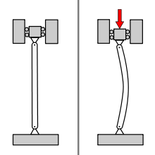
If the load on a column is applied through the center of gravity (centroid) of its cross section, it is called an axial load. A load at any other point in the cross section is known as an eccentric load. A short column under the action of an axial load will fail by direct compression before it buckles, but a long column loaded in the same manner will fail by springing suddenly outward laterally (buckling) in a bending mode. The buckling mode of deflection is considered a failure mode, and it generally occurs before the axial compression stresses (direct compression) can cause failure of the material by yielding or fracture of that compression member. However, intermediate-length columns will fail by a combination of direct compressive stress and bending.
In particular:
- A short steel column is one whose slenderness ratio does not exceed 50; an intermediate length steel column has a slenderness ratio ranging from about 50 to 200, and its behavior is dominated by the strength limit of the material, while a long steel column may be assumed to have a slenderness ratio greater than 200 and its behavior is dominated by the modulus of elasticity of the material.
- A short concrete column is one having a ratio of unsupported length to least dimension of the cross section equal to or less than 10. If the ratio is greater than 10, it is considered a long column (sometimes referred to as a slender column).
- Timber columns may be classified as short columns if the ratio of the length to least dimension of the cross section is equal to or less than 10. The dividing line between intermediate and long timber columns cannot be readily evaluated. One way of defining the lower limit of long timber columns would be to set it as the smallest value of the ratio of length to least cross sectional area that would just exceed a certain constant K of the material. Since K depends on the modulus of elasticity and the allowable compressive stress parallel to the grain, it can be seen that this arbitrary limit would vary with the species of the timber. The value of K is given in most structural handbooks.
The theory of the behavior of columns was investigated in 1757 by mathematician Leonhard Euler. He derived the formula, the Euler formula, that gives the maximum axial load that a long, slender, ideal column can carry without buckling. An ideal column is one that is perfectly straight, made of a homogeneous material, and free from initial stress. When the applied load reaches the Euler load, sometimes called the critical load, the column comes to be in a state of unstable equilibrium. At that load, the introduction of the slightest lateral force will cause the column to fail by suddenly "jumping" to a new configuration, and the column is said to have buckled. This is what happens when a person stands on an empty aluminum can and then taps the sides briefly, causing it to then become instantly crushed (the vertical sides of the can understood as an infinite series of extremely thin columns). The formula derived by Euler for long slender columns is given below.

To get the mathematical demonstration read: Euler's critical load
where
- = maximum or critical force (vertical load on column),
- = modulus of elasticity,
- = smallest area moment of inertia of the cross section of the column,
- = unsupported length of column,
-
= column effective length factor, whose value depends on the conditions of end support of the column, as follows.
- For both ends pinned (hinged, free to rotate), = 1.0.
- For both ends fixed, = 0.50.
- For one end fixed and the other end pinned, = √2/2 ≈ 0.7071.
- For one end fixed and the other end free to move laterally, = 2.0.
- is the effective length of the column.


Examination of this formula reveals the following facts with regard to the load-bearing ability of slender columns.
- The elasticity of the material of the column and not the compressive strength of the material of the column determines the column's buckling load.
- The buckling load is directly proportional to the second moment of area of the cross section.
- The boundary conditions have a considerable effect on the critical load of slender columns. The boundary conditions determine the mode of bending of the column and the distance between inflection points on the displacement curve of the deflected column. The inflection points in the deflection shape of the column are the points at which the curvature of the column changes sign and are also the points at which the column's internal bending moments of the column are zero. The closer the inflection points are, the greater the resulting axial load capacity (bucking load) of the column.

A conclusion from the above is that the buckling load of a column may be increased by changing its material to one with a higher modulus of elasticity (E), or changing the design of the column's cross section so as to increase its moment of inertia. The latter can be done without increasing the weight of the column by distributing the material as far from the principal axis of the column's cross section as possible. For most purposes, the most effective use of the material of a column is that of a tubular section.
Another insight that may be gleaned from this equation is the effect of length on critical load. Doubling the unsupported length of the column quarters the allowable load. The restraint offered by the end connections of a column also affects its critical load. If the connections are perfectly rigid (does not allowing rotation of its ends), the critical load will be four times that for a similar column where the ends are pinned (allowing rotation of its ends).
Since the radius of gyration is defined as the square root of the ratio of the column's moment of inertia about an axis to its cross sectional area, the above Euler formula may be reformatted by substituting the radius of gyration A·r2 for I:

where is the stress that causes buckling the column, and is the slenderness ratio.


Since structural columns are commonly of intermediate length, the Euler formula has little practical application for ordinary design. Issues that cause deviation from the pure Euler column behaviour include imperfections in geometry of the column in combination with plasticity/non-linear stress strain behaviour of the column's material. Consequently, a number of empirical column formulae have been developed that agree with test data, all of which embody the slenderness ratio. Due to the uncertainty in the behavior of columns, for design, appropriate safety factors are introduced into these formulae. One such formula is the Perry Robertson formula which estimates the critical buckling load based on an assumed small initial curvature, hence an eccentricity of the axial load. The Rankine Gordon formula (Named for William John Macquorn Rankine and Perry Hugesworth Gordon (1899 – 1966)) is also based on experimental results and suggests that a column will buckle at a load Fmax given by:

where Fe is the Euler maximum load and Fc is the maximum compressive load. This formula typically produces a conservative estimate of Fmax.
Self-buckling
To get the mathematical demonstration read: Self-buckling
A free-standing, vertical column, with density , Young's modulus , and cross-sectional area , will buckle under its own weight if its height exceeds a certain critical value:[1][2][3]


where g is the acceleration due to gravity, I is the second moment of area of the beam cross section, and B is the first zero of the Bessel function of the first kind of order -1/3, which is equal to 1.86635086…
Buckling under tensile dead loading
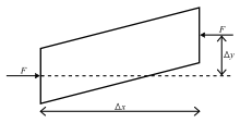
Usually buckling and instability are associated with compression, but buckling and instability can also occur in elastic structures subject to dead tensile load.[4]
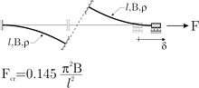
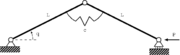
An example of a single-degree-of-freedom structure is shown in Fig. 2, where the critical load is also indicated. Another example involving flexure of a structure made up of beam elements governed by the equation of the Euler's elastica is shown in Fig.3. In both cases, there are no elements subject to compression. The instability and buckling in tension are related to the presence of the slider, the junction between the two rods, allowing only relative sliding between the connected pieces. Watch a movie for more details.
Constraints, curvature and multiple buckling
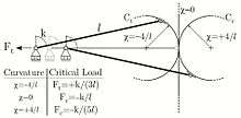
Buckling of an elastic structure strongly depends on the curvature of the constraints against which the ends of the structure are prescribed to move (see Bigoni, Misseroni, Noselli and Zaccaria, 2012[5]). In fact, even a single-degree-of-freedom system (see Fig.3) may exhibit a tensile (or a compressive) buckling load as related to the fact that one end has to move along the circular profile labeled 'Ct' (labelled 'Cc').

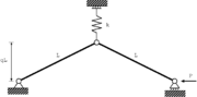
The two circular profiles can be arranged in a 'S'-shaped profile, as shown in Fig.4; in that case a discontinuity of the constraint's curvature is introduced, leading to multiple bifurcations. Note that the single-degree-of-freedom structure shown in Fig.4 has two buckling loads (one tensile and one compressive). Watch a movie for more details.
Flutter instability
Structures subject to a follower (nonconservative) load may suffer instabilities which are not of the buckling type and therefore are not detectable with a static approach.[6] For instance, the so-called 'Ziegler column' is shown in Fig.5.
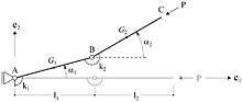
This two-degree-of-freedom system does not display a quasi-static buckling, but becomes dynamically unstable. To see this, we note that the equations of motion are
![{\displaystyle {\begin{aligned}{\frac {1}{3}}\rho l_{1}^{2}\left(l_{1}+3l_{2}\right){\ddot {\alpha }}_{1}+{\frac {1}{2}}\rho l_{1}l_{2}^{2}\cos(\alpha _{1}-\alpha _{2}){\ddot {\alpha }}_{2}+{\frac {1}{2}}\rho l_{1}l_{2}^{2}\sin(\alpha _{1}-\alpha _{2}){\dot {\alpha }}_{2}^{2}+{}&\\(k_{1}+k_{2})\alpha _{1}-k_{2}\alpha _{2}+(\beta _{1}+\beta _{2}){\dot {\alpha }}_{1}-\beta _{2}{\dot {\alpha }}_{2}-l_{1}P\sin(\alpha _{1}-\alpha _{2})&=0,\\[6pt]{\frac {1}{2}}\rho l_{1}l_{2}^{2}\cos(\alpha _{1}-\alpha _{2}){\ddot {\alpha }}_{1}+{\frac {1}{3}}\rho l_{2}^{3}{\ddot {\alpha }}_{2}-{\frac {1}{2}}\rho l_{1}l_{2}^{2}\sin(\alpha _{1}-\alpha _{2}){\dot {\alpha }}_{1}^{2}-{}&\\k_{2}(\alpha _{1}-\alpha _{2})-\beta _{2}({\dot {\alpha }}_{1}-{\dot {\alpha }}_{2})&=0,\end{aligned}}}](../I/m/49d74410c25d583bc2d7614895d0b5c7be3b2707.svg)
and their linearized version is

Assuming a time-harmonic solution in the form

we find the critical loads for flutter ( ) and divergence ( ),


where and .


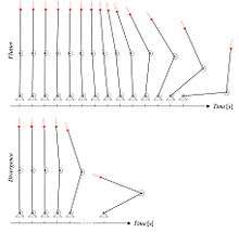
Flutter instability corresponds to a vibrational motion of increasing amplitude and is shown in Fig.6 (upper part) together with the divergence instability (lower part) consisting in an exponential growth.
Recently, Bigoni and Noselli (2011)[7] have experimentally shown that flutter and divergence instabilities can be directly related to dry friction, watch the movie for more details.
Various forms of buckling
Buckling is a state which defines a point where an equilibrium configuration becomes unstable under a parametric change of load and can manifest itself in several different phenomena. All can be classified as forms of bifurcation.
There are four basic forms of bifurcation associated with loss of structural stability or buckling in the case of structures with a single degree of freedom. These comprise two types of pitchfork bifurcation, one saddle-node bifurcation (often referred to as a limit point) and one transcritical bifurcation. The pitchfork bifurcations are the most commonly studied forms and include the buckling of columns, sometimes known as Euler buckling; the buckling of plates, sometimes known as local buckling, which is well known to be relatively safe (both are supercritical phenomena) and the buckling of shells, which is well-known to be a highly dangerous (subcritical phenomenon).[8] Using the concept of potential energy, equilibrium is defined as a stationary point with respect to the degree(s) of freedom of the structure. We can then determine whether the equilibrium is stable, as in the case where the stationary point is a local minimum; or unstable, as in the case where the stationary point is a maximum point of inflection or saddle point (for multiple-degree-of-freedom structures only) – see animations below.


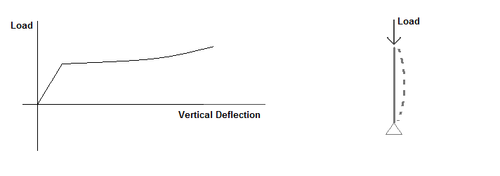
In Euler buckling,[9][10] when the applied load is increased by a small amount beyond the critical load, the structure deforms into a buckled configuration which is adjacent to the original configuration. For example, the Euler column pictured will start to bow when loaded slightly above its critical load, but will not suddenly collapse.
In structures experiencing limit point instability, if the load is increased infinitesimally beyond the critical load, the structure undergoes a large deformation into a different stable configuration which is not adjacent to the original configuration. An example of this type of buckling is a toggle frame (pictured) which 'snaps' into its buckled configuration.
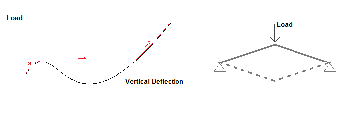
Plate Buckling
A plate is a 3-dimensional structure defined as having a width of comparable size to its length, with a thickness is very small in comparison to its other two dimensions. Similar to columns, thin plates experience out-of-plane buckling deformations when subjected to critical loads; however, contrasted to column buckling, plates under buckling loads can continue to carry loads, called local buckling. This phenomenon is incredibly useful in numerous systems, as it allows systems to be engineered to provide greater loading capacities.
For a rectangular plate, supported along every edge, loaded with a uniform compressive force per unit length, the derived governing equation can be stated by:[11]

where
- = out-of-plane deflection
- = uniformly distributed compressive load
- = Poisson's Ratio
- = modulus of elasticity
- = thickness


The solution to the deflection can be expanded into two harmonic functions shown:[11]

where
- = number of half sine curvatures that occur lengthwise
- = number of half sine curvatures that occur widthwise
- = length of specimen
- = width of specimen


The previous equation can be substituted into the earlier differential equation where equals 1. can be separated providing the equation for the critical compressive loading of a plate:[11]

where
- = buckling coefficient, given by:[11]


The buckling coefficient is influenced by the aspect of the specimen, / , and the number of lengthwise curvatures. For an increasing number of such curvatures, the aspect ratio produces a varying buckling coefficient; but each relation provides a minimum value for each . This minimum value can then be used as a constant, independent from both the aspect ratio and .[11]

Given stress is found by the load per unit area, the following expression is found for the critical stress:

From the derived equations, it can be seen the close similarities between the critical stress for a column and for a plate. As the width shrinks, the plate acts more like a column as it increases the resistance to buckling along the plate’s width. The increase of allows for an increase of the number of sine waves produced by buckling along the length, but also increases the resistance from the buckling along the width.[11] This creates the preference of the plate to buckle in such a way to equal the number of curvatures both along the width and length. Due to boundary conditions, when a plate is loaded with a critical stress and buckles, the edges perpendicular to the load cannot deform out-of-plane and will therefore continue to carry the stresses. This creates a non-uniform compressive loading along the ends, where the stresses are imposed on half of the effective width on either side of the specimen, given by the following:[11]

where
- = effective width
- = yielding stress


As the loaded stress increase, the effective width continues to shrink; if the stresses on the ends ever reaches the yield stress, the plate will fail. This is what allows the buckled structure to continue supporting loadings. When the axial load over the critical load is plotted against the displacement, the fundamental path is shown. It demonstrates the plate's similarity to a column under buckling; however, past the buckling load, the fundamental path bifurcates into a secondary path that curves upward, providing the ability to be subjected to higher loads past the critical load.
Bicycle wheels
A conventional bicycle wheel consists of a thin rim kept under high compressive stress by the (roughly normal) inward pull of a large number of spokes. It can be considered as a loaded column that has been bent into a circle. If spoke tension is increased beyond a safe level, the wheel spontaneously fails into a characteristic saddle shape (sometimes called a "taco" or a "pringle") like a three-dimensional Euler column. This is normally a purely elastic deformation and the rim will resume its proper plane shape if spoke tension is reduced slightly.
Surface materials

Buckling is also a failure mode in pavement materials, primarily with concrete, since asphalt is more flexible. Radiant heat from the sun is absorbed in the road surface, causing it to expand, forcing adjacent pieces to push against each other. If the stress is great enough, the pavement can lift up and crack without warning. Going over a buckled section can be very jarring to automobile drivers, described as running over a speed hump at highway speeds.
Similarly, rail tracks also expand when heated, and can fail by buckling, a phenomenon called sun kink. It is more common for rails to move laterally, often pulling the underlain railroad ties (sleepers) along.
Cause
The buckling force in the track due to warming up is a function of the rise in temperature only and is independent of the track length:
- .

Derivation of buckling force function:
The linear thermal expansion due to heating of the track is found using

where
- ΔL = thermal expansion of the rail
- L = length of the rail/track
- α = coefficient of thermal expansion
- ΔT = increase in temperature
According to Hooke's law the extension due to a force (in the rail) is

where
- ΔL = extension of the rail/track
- F = the force extending a rod, here the induced force in the rail
- E = modulus of elasticity of rail material (steel)
- A = cross section of rail
- L = length of rail
Putting these together gives

Accidents
These accidents were deemed to be sun kink related (more information available at List of rail accidents (2000–2009)):
- April 18, 2002 Amtrak Auto-Train derailment, off CSX tracks, near Crescent City, Florida.
- July 29, 2002 Amtrak Capitol Limited derails, off CSX tracks, near Kensington, Maryland.
- July 8, 2010 CSX train derails off tracks in Waxhaw, North Carolina.
- July 6, 2012 WMATA Metrorail train derails off tracks near Hyattsville, Maryland.[12]
Energy method
Often it is very difficult to determine the exact buckling load in complex structures using the Euler formula, due to the difficulty in determining the constant K. Therefore, maximum buckling load is often approximated using energy conservation and referred to as an energy method in structural analysis.
The first step in this method is to assume a displacement mode and a function that represents that displacement. This function must satisfy the most important boundary conditions, such as displacement and rotation. The more accurate the displacement function, the more accurate the result.
The method assumes that the system (the column) is a conservative system in which energy is not dissipated as heat, hence the energy added to the column by the applied external forces is stored in the column in the form of strain energy.

In this method, there are two equations used (for small deformations) to approximate the "strain" energy (the potential energy stored as elastic deformation of the structure) and "applied" energy (the work done on the system by external forces).

where is the displacement function and the subscripts and refer to the first and second derivatives of the displacement. Energy conservation yields:


Flexural-torsional buckling
Flexural-torsional buckling can be described as a combination of bending and twisting response of a member in compression. Such a deflection mode must be considered for design purposes. This mostly occurs in columns with "open" cross-sections and hence have a low torsional stiffness, such as channels, structural tees, double-angle shapes, and equal-leg single angles. Circular cross sections do not experience such a mode of bucking.
Lateral-torsional buckling

When a simply supported beam is loaded in flexure, the top side is in compression, and the bottom side is in tension. If the beam is not supported in the lateral direction (i.e., perpendicular to the plane of bending), and the flexural load increases to a critical limit, the beam will experience a lateral deflection of the compression flange. The lateral deflection of the compression flange is restrained by the beam web and tension flange, but for an open section the twisting mode is more flexible, hence the beam both twists and deflects laterally in a failure mode known as lateral-torsional buckling. In wide-flange sections (with high lateral bending stiffness), the deflection mode will be mostly twisting in torsion. In narrow-flange sections, the bending stiffness is lower and the column's deflection will be closer to that of lateral bucking deflection mode.
The modification factor (Cb)
Cb is a modification factor used in the equation for nominal flexural strength when determining lateral-torsional buckling. The reason for this factor is to allow for non-uniform moment diagrams when the ends of a beam segment are braced. The conservative value for Cb can be taken as 1, regardless of beam configuration or loading, but in some cases it may be excessively conservative. Cb is always equal to or greater than 1, never less. For cantilevers or overhangs where the free end is unbraced, Cb is equal to 1. Tables of values of Cb for simply supported beams exist.
If an appropriate value of Cb is not given in tables, it can be obtained via the following formula:

where
- = absolute value of maximum moment in the unbraced segment,
- = absolute value of maximum moment at quarter point of the unbraced segment,
- = absolute value of maximum moment at centerline of the unbraced segment,
- = absolute value of maximum moment at three-quarter point of the unbraced segment,


The result is the same for all unit systems.
Plastic buckling
The buckling strength of a member is less than the elastic buckling strength of a structure if the material of the member is stressed beyond the elastic material range and into the non-linear (plastic) material behavior range. When the compression load is near the buckling load, the structure will bend significantly and the material of the column will diverge from a linear stress-strain behavior. The stress-strain behavior of materials is not strictly linear even below the yield point, hence the modulus of elasticity decreases as stress increases, and significantly so as the stresses approach the material's yield strength. This reduced material rigidity reduces the buckling strength of the structure and results in a bucking load less than that predicted by the assumption of linear elastic behavior.
A more accurate approximation of the buckling load can be had by the use of the tangent modulus of elasticity, Et, which is less than the elastic modulus, in place of the elastic modulus of elasticity. The tangent is equal to the elastic modulus and then decreases beyond the proportional limit. The tangent modulus is a line drawn tangent to the stress-strain curve at a particular value of strain (in the elastic section of the stress-strain curve, the tangent modulus is equal to the elastic modulus). Plots of the tangent modulus of elasticity for a variety of materials are available in standard references.
Dynamic buckling
If a column is loaded suddenly and then the load released, the column can sustain a much higher load than its static (slowly applied) buckling load. This can happen in a long, unsupported column used as a drop hammer. The duration of compression at the impact end is the time required for a stress wave to travel along the column to the other (free) end and back down as a relief wave. Maximum buckling occurs near the impact end at a wavelength much shorter than the length of the rod, and at a stress many times the buckling stress of a statically-loaded column. The critical condition for buckling amplitude to remain less than about 25 times the effective rod straightness imperfection at the buckle wavelength is

where is the impact stress, is the length of the rod, is the elastic wave speed, and is the smaller lateral dimension of a rectangular rod. Because the buckle wavelength depends only on and , this same formula holds for thin cylindrical shells of thickness .[13]


Buckling of thin cylindrical shells subject to axial loads
Solutions of Donnell's eight order differential equation gives the various buckling modes of a thin cylinder under compression. But this analysis, which is in accordance with the small deflection theory gives much higher values than shown from experiments. So it is customary to find the critical buckling load for various structures which are cylindrical in shape from empirically based design curves wherein the critical buckling load Fcr is plotted against the ratio R/t, where R is the radius and t is the thickness of the cylinder for various values of L/R, L the length of the cylinder. If cut-outs are present in the cylinder, critical buckling loads as well as pre-buckling modes will be affected. Presence or absence of reinforcements of cut-outs will also affect the buckling load.
Buckling of pipes and pressure vessels subject to external overpressure
Pipes and pressure vessels subject to external overpressure, caused for example by steam cooling within the pipe and condensing into water with subsequent massive pressure drop, risk buckling due to compressive hoop stresses. Design rules for calculation of the required wall thickness or reinforcement rings are given in various piping and pressure vessel codes.
Cerebral cortex
The mechanisms of cortical gyrification are just beginning to be understood.[14] Mechanical buckling forces due to the expanding brain tissue probably cause the cortical surface to fold.[15] This is an example of how pattern formation in nature can also take place due to elastic instabilities[16] instead of the classical reaction-diffusion mechanism first proposed by Alan Turing.[17]
See also
References
- ↑ Kato, K. (1915). "Mathematical Investigation on the Mechanical Problems of Transmission Line". Journal of the Japan Society of Mechanical Engineers. 19: 41.
- ↑ Ratzersdorfer, Julius (1936). Die Knickfestigkeit von Stäben und Stabwerken [The buckling resistance of members and frames] (in German). Wein, Austria: J. Springer. pp. 107–109. ISBN 978-3-662-24075-5.
- ↑ Cox, Steven J.; C. Maeve McCarthy (1998). "The Shape of the Tallest Column". Society for Industrial and Applied Mathematics. 29: 547–554. doi:10.1137/s0036141097314537.
- ↑ Zaccaria, D.; Bigoni, D.; Noselli, G.; Misseroni, D. (21 April 2011). "Structures buckling under tensile dead load" (PDF). Proceedings of the Royal Society A. 467 (2130): 1686–1700. Bibcode:2011RSPSA.467.1686Z. doi:10.1098/rspa.2010.0505.
- ↑ Bigoni, D.; Misseroni, D.; Noselli, G.; Zaccaria, D. (2012). "Effects of the constraint's curvature on structural instability: tensile buckling and multiple bifurcations". Proceedings of the Royal Society A. 468: 2191–2209. arXiv:1201.4701. Bibcode:2012RSPSA.468.2191B. doi:10.1098/rspa.2011.0732.
- ↑ Bigoni, D. (2012). Nonlinear Solid Mechanics: Bifurcation Theory and Material Instability. Cambridge University Press. ISBN 9781107025417.
- ↑ Bigoni, D.; Noselli, G. (2011). "Experimental evidence of flutter and divergence instabilities induced by dry friction". Journal of the Mechanics and Physics of Solids. 59: 2208–2226. Bibcode:2011JMPSo..59.2208B. doi:10.1016/j.jmps.2011.05.007.
- ↑ Thompson, J. M. T.; Hunt, G. W. (1973). A general theory of elastic stability. Wiley. ISBN 978-0471859918.
- ↑ Jones, Robert M. (1 December 2007). Buckling of Bars, Plates, and Shells. CRC. ISBN 978-1560328278.
- ↑ Earls, Christopher J. (2007). Observations on eigenvalue buckling analysis within a finite element context. Proceedings of the Structural Stability Research Council, Annual Stability Conference. New Orleans, LA.
- 1 2 3 4 5 6 7 Bulson, P. S. (1970). Theory of Flat Plates. Chatto and Windus, London.
- ↑ http://dcist.com/2012/07/excessive_heat_probable_cause_in_gr.php%5Bpermanent+dead+link%5D
- ↑ Lindberg, H. E.; Florence, A. L. (1987). Dynamic Pulse Buckling. Martinus Nijhoff Publishers. pp. 11–56, 297–298.
- ↑ Kuhl, Ellen (2016). "Biophysics: Unfolding the brain". Nature Physics. 12 (6): 533–534. Bibcode:2016NatPh..12..533K. doi:10.1038/nphys3641.
- ↑ Ronan, L; Voets, N; Rua, C; Alexander-Bloch, A; Hough, M; Mackay, C; Crow, TJ; James, A; Giedd, JN; Fletcher, PC (August 2014). "Differential tangential expansion as a mechanism for cortical gyrification". Cerebral Cortex. 24 (8): 2219–28. doi:10.1093/cercor/bht082. PMC 4089386. PMID 23542881.
- ↑ Matsumoto, E. A., & Kamien, R. D. (2009). Elastic-Instability Triggered Pattern Formation. Retrieved from http://repository.upenn.edu/physics_papers/75
- ↑ S. Kondo, T. Miura, "Reaction-Diffusion Model as a Framework for Understanding Biological Pattern Formation", Science 24 Sep 2010: Vol. 329, Issue 5999, pp. 1616-1620 doi:10.1126/science.1179047
Further reading
- Timoshenko, S. P., and Gere, J. M., Theory of Elastic Stability, 2 ed., McGraw-Hill, 1961.
- Nenezich, M., Thermoplastic Continuum Mechanics, Journal of Aerospace Structures, Vol. 4, 2004.
- The Stability of Elastic Equilibrium by W. T. Koiter, PhD Thesis, 1945.
- Dhakal Rajesh and Koichi Maekawa (October 2002). "Reinforcement Stability and Fracture of Cover Concrete in Reinforced Concrete Members”.
- Willian T. Segui (2007). “Steel Design” Fourth Edition. United States. Chris Carson.
- Analysis and design of flight vehicle structures- E.F.Bruhn
External links
- The complete theory and example experimental results for long columns are available as a 39-page PDF document at http://lindberglce.com/tech/buklbook.htm
- Laboratory for Physical Modeling of Structures and Photoelasticity (University of Trento, Italy)
- https://web.archive.org/web/20100401042249/http://www.midasuser.com.tw/t_support/tech_pds/files/Tech%20Note-Lateral%20Torsional%20Buckling.pdf