Creep (deformation)
In materials science, creep (sometimes called cold flow) is the tendency of a solid material to move slowly or deform permanently under the influence of mechanical stresses. It can occur as a result of long-term exposure to high levels of stress that are still below the yield strength of the material. Creep is more severe in materials that are subjected to heat for long periods, and generally increases as they near their melting point.
The rate of deformation is a function of the material's properties, exposure time, exposure temperature and the applied structural load. Depending on the magnitude of the applied stress and its duration, the deformation may become so large that a component can no longer perform its function — for example creep of a turbine blade will cause the blade to contact the casing, resulting in the failure of the blade. Creep is usually of concern to engineers and metallurgists when evaluating components that operate under high stresses or high temperatures. Creep is a deformation mechanism that may or may not constitute a failure mode. For example, moderate creep in concrete is sometimes welcomed because it relieves tensile stresses that might otherwise lead to cracking.
Unlike brittle fracture, creep deformation does not occur suddenly upon the application of stress. Instead, strain accumulates as a result of long-term stress. Therefore, creep is a "time-dependent" deformation.
Temperature dependence
The temperature range in which creep deformation may occur differs in various materials. Lead can creep at room temperature and tungsten requires a temperature in the thousands of degrees before creep deformation can occur, while ice will creep at temperatures near 0 °C (32 °F).[1] As a general guideline, the effects of creep deformation generally become noticeable at approximately 35% of the melting point and at 45% of melting point for ceramics.[2] Virtually any material will creep upon approaching its melting temperature. Since the creep minimum temperature is related to the melting point, creep can be seen at relatively low temperatures for some materials. Plastics and low-melting-temperature metals, including many solders, can begin to creep at room temperature, as can be seen markedly in old lead hot-water pipes. Glacier flow is an example of creep processes in ice.[3]
Stages of creep
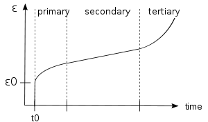
In the initial stage, or primary creep, or transient creep, the strain rate is relatively high, but decreases with increasing time and strain due to a process analogous to work hardening at lower temperatures. For instance, the dislocation density increases and, in many materials, a dislocation subgrain structure is formed and the cell size decreases with strain.[4] The strain rate diminishes to a minimum and becomes near constant as the secondary stage begins. This is due to the balance between work hardening and annealing (thermal softening). The secondary stage, referred to as "steady-state creep", is the most understood. The microstructure is invariant during this stage, which means that recovery effects are concurrent with deformation. No material strength is lost during these first two stages of creep.
The characterized "creep strain rate" typically refers to the constant rate in this secondary stage. Stress dependence of this rate depends on the creep mechanism. In tertiary creep, the strain rate exponentially increases with stress because of necking phenomena or internal cracks or voids decreases the effective area of the specimen. Strength is quickly lost in this stage while the material's shape is permanently changed. The acceleration of creep deformation in the tertiary stage eventually leads to material fracture.[5]
Mechanisms of creep deformation
The mechanism of creep depends on temperature and stress. Under the conditions of different temperature and applied stress, dislocation glide, dislocation climb, or diffusional-flow mechanisms may dominate creep deformation. Some mechanisms of creep, especially those involving dislocations, have not been verified by direct microstructural examination yet.[4] However, processes just like the mechanisms conjectured should happen during creep deformation.
Various mechanisms are:
- Bulk diffusion (Nabarro-Herring creep)
- Climb — here the strain is actually accomplished by climb
- Climb-assisted glide — here the climb is an enabling mechanism, allowing dislocations to get around obstacles
- Grain boundary diffusion (Coble creep)
- Thermally activated glide — e.g., via cross-slip
General creep equation

where is the creep strain, C is a constant dependent on the material and the particular creep mechanism, m and b are exponents dependent on the creep mechanism, Q is the activation energy of the creep mechanism, σ is the applied stress, d is the grain size of the material, k is Boltzmann's constant, and T is the absolute temperature.[6]

Dislocation creep
At high stresses (relative to the shear modulus), creep is controlled by the movement of dislocations. For dislocation creep, Q = Q(self diffusion), m = 4–6, and b = 0. Therefore, dislocation creep has a strong dependence on the applied stress and the intrinsic activation energy, but no grain size dependence.
Some alloys exhibit a very large stress exponent (m > 10), and this has typically been explained by introducing a "threshold stress," σth, below which creep can't be measured. The modified power law equation then becomes:

where A, Q and n can all be explained by conventional mechanisms (so 3 ≤ m ≤ 10). The creep increases with increasing applied stress, since the applied stress tends to drive the dislocation past the barrier, and make the dislocation get into a lower energy state after bypassing the obstacle, which means that the dislocation is inclined to pass the obstacle. In other words, part of the work required to overcome the energy barrier of passing an obstacle is provided by the applied stress and the remainder by thermal energy.
Nabarro–Herring creep
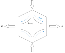
Nabarro–Herring (NH) creep is a form of diffusion creep, while dislocation glide creep does not involve atomic diffusion. Nabarro-Herring creep dominates at high temperatures and low stresses. As shown in the figure on the right, the lateral sides of the crystal are subjected to a tensile stress, and the horizontal sides to a compressive stress. The atomic volume is altered by applied stress: it increases in regions under tension and decreases in regions under compression. So the activation energy for vacancy formation is changed by ± , where is the atomic volume, the " " sign is for compressive regions and " " sign is for tensile regions. Since the fractional vacancy concentration is proportional to , where is the vacancy-formation energy, the vacancy concentration is higher in tensile regions than in compressive regions, leading to a net flow of vacancies from the regions under tension to the regions under compression, and this is equivalent to a net atom diffusion in the opposite direction, which causes the creep deformation: the grain elongates in the tensile stress axis and contracts in the compressive stress axis.


In Nabarro–Herring creep, k is related to the diffusion coefficient of atoms through the lattice, Q = Q (self diffusion), m = 1, and b = 2. Therefore, Nabarro–Herring creep has a weak stress dependence and a moderate grain size dependence, with the creep rate decreasing as grain size is increased.
Nabarro–Herring creep is strongly temperature dependent. For lattice diffusion of atoms to occur in a material, neighboring lattice sites or interstitial sites in the crystal structure must be free. A given atom must also overcome the energy barrier to move from its current site (it lies in an energetically favorable potential well) to the nearby vacant site (another potential well). The general form of the diffusion equation is D = D0exp(E/KT) where D0 has a dependence on both the attempted jump frequency and the number of nearest neighbor sites and the probability of the sites being vacant. Thus there is a double dependence upon temperature. At higher temperatures the diffusivity increases due to the direct temperature dependence of the equation, the increase in vacancies through Schottky defect formation, and an increase in the average energy of atoms in the material. Nabarro–Herring creep dominates at very high temperatures relative to a material's melting temperature.
Coble creep
Coble creep is a second form of diffusion controlled creep. In Coble creep the atoms diffuse along grain boundaries to elongate the grains along the stress axis. This causes Coble creep to have a stronger grain size dependence than Nabarro–Herring creep, thus, Coble creep will be more important in materials composed of very fine grains. For Coble creep k is related to the diffusion coefficient of atoms along the grain boundary, Q = Q(grain boundary diffusion), m = 1, and b = 3. Because Q(grain boundary diffusion) < Q(self diffusion), Coble creep occurs at lower temperatures than Nabarro–Herring creep. Coble creep is still temperature dependent, as the temperature increases so does the grain boundary diffusion. However, since the number of nearest neighbors is effectively limited along the interface of the grains, and thermal generation of vacancies along the boundaries is less prevalent, the temperature dependence is not as strong as in Nabarro–Herring creep. It also exhibits the same linear dependence on stress as Nabarro–Herring creep. Generally, the diffusional creep rate should be the sum of Nabarro–Herring creep rate and Coble creep rate. Diffusional creep leads to grain-boundary separation, that is, voids or cracks form between the grains. To heal this, grain-boundary sliding occurs. The diffusional creep rate and the grain boundary sliding rate must be balanced if there are no voids or cracks remaining. When grain-boundary sliding can not accommodate the incompatibility, grain-boundary voids are generated, which is related to the initiation of creep fracture.
Solute drag creep
Solute drag creep is one kind of mechanisms for power law creep (PLC), involving both dislocation and diffusional flow. Solute drag creep is observed in certain metallic alloys. Their creep rate increases during the first stage of creep before a steady-state, which can be explained by a model associated with solid-solution strengthening. The size misfit between solute atoms and edge dislocations could restrict dislocation motion. The flow stress required for dislocations to move is increased at low temperatures due to immobility of the solute atoms. But solute atoms are mobile at higher temperatures, so the solute atoms could move along with edge dislocations as a "drag" on their motion, if the dislocation motion or the creep rate is not too high. The solute drag creep rate is:

where C is a constant, is the solute diffusivity, is the solute concentration, and is the misfit parameter, is the applied stress. So it could be seen from the equation above, m is 3 for solute drag creep. Solute drag creep shows a special phenomenon, which is called the Portevin-Le Chatelier effect. When the applied stress becomes sufficiently large, the dislocations will break away from the solute atoms since dislocation velocity increases with the stress. After breakaway, the stress decreases and the dislocation velocity also decreases, which allows the solute atoms to approach and reach the previously departed dislocations again, leading to a stress increase. The process repeats itself when the next local stress maximum is obtained. So repetitive local stress maxima and minima could be detected during solute drag creep.


Dislocation climb-glide creep
Dislocation climb-glide creep is observed in materials at high temperature. The initial creep rate is larger than the steady-state creep rate. Climb-glide creep could be illustrated as follows: when the applied stress is not enough to for a moving dislocation to overcome the obstacle on its way via dislocation glide alone, the dislocation could climb to a parallel slip plane by diffusional processes, and the dislocation can glide on the new plane. This process repeats itself each time when the dislocation encounters an obstacle. The creep rate could be written as:

where ACG includes details of the dislocation loop geometry, DL is the lattice diffusivity, M is the number of dislocation sources per unit volume, is the applied stress, and is the atomic volume. The exponent m for dislocation climb-glide creep is 4.5 if M is independent of stress and this value of m is consistent with results from considerable experimental studies.
Harper–Dorn creep
Harper–Dorn creep is a climb-controlled dislocation mechanism at low stresses that has been observed in aluminum, lead, and tin systems, in addition to nonmetal systems such as ceramics and ice. It is characterized by two principal phenomena: a linear relationship between the steady-state strain rate and applied stress at a constant temperature, and an independent relationship between the steady-state strain rate and grain size for a provided temperature and applied stress. The latter observation implies that Harper–Dorn creep is controlled by dislocation movement; namely, since creep can occur by vacancy diffusion (Nabarro–Herring creep, Coble creep), grain boundary sliding, and/or dislocation movement, and since the first two mechanisms are grain-size dependent, Harper–Dorn creep must therefore be dislocation-motion dependent.[7]
However, Harper–Dorn creep is typically overwhelmed by other creep mechanisms in most situations, and is therefore not observed in most systems. The phenomenological equation which describes Harper–Dorn creep is:

where: is dislocation density (constant for Harper–Dorn creep), is the diffusivity through the volume of the material, is the shear modulus, is the Burger's vector, is the applied stress, is Boltzmann's constant, and is temperature.


The volumetric activation energy indicates that the rate of Harper–Dorn creep is controlled by vacancy diffusion to and from dislocations, resulting in climb-controlled dislocation motion.[8][9] Unlike in other creep mechanisms, the dislocation density here is constant and independent of the applied stress.[7] Moreover, the dislocation density must be low for Harper–Dorn creep to dominate. The density has been proposed to increase as dislocations move via cross-slip from one slip-plane to another, thereby increasing the dislocation length per unit volume. Cross-slip can also result in jogs along the length of the dislocation, which, if large enough, can act as single-ended dislocation sources.[10]
Sintering
At high temperatures, it is energetically favorable for voids to shrink in a material. The application of tensile stress opposes the reduction in energy gained by void shrinkage. Thus, a certain magnitude of applied tensile stress is required to offset these shrinkage effects and cause void growth and creep fracture in materials at high temperature. This stress occurs at the sintering limit of the system.[11]
The stress tending to shrink voids that must be overcome is related to the surface energy and surface area-volume ratio of the voids. For a general void with surface energy γ and principle radii of curvature of r1 and r2, the sintering limit stress is:[12]

Below this critical stress, voids will tend to shrink rather than grow. Additional void shrinkage effects will also result from the application of a compressive stress. For typical descriptions of creep, it is assumed that the applied tensile stress exceeds the sintering limit.
Creep also explains one of several contributions to densification during metal powder sintering by hot pressing. A main aspect of densification is the shape change of the powder particles. Since this change involves permanent deformation of crystalline solids, it can be considered a plastic deformation process and thus sintering can be described as a high temperature creep process.[13] The applied compressive stress during pressing accelerates void shrinkage rates and allows a relation between the steady-state creep power law and densification rate of the material. This phenomenon is observed to be one of the main densification mechanisms in the final stages of sintering, during which the densification rate (assuming gas-free pores) can be explained by:[14][15]
![{\displaystyle {\dot {\rho }}={3A \over 2}{\rho (1-\rho ) \over [1-(1-\rho )^{1 \over n}]^{n}}\left({3 \over 2}{P_{e} \over n}\right)^{n}}](../I/m/1aa6c4be07825b353687d2375a9ead4af2ae42a5.svg)
In which is the densification rate, is the density, is the pressure applied, n describes the exponent of strain rate behavior, and A is a mechanism-dependent constant. A and n are from the following form of the general steady-state creep equation:


Where is the strain rate, and is the tensile stress. For the purposes of this mechanism, the constant A comes from the following expression, where A' is a dimensionless, experimental constant, μ is the shear modulus, b is the Burgers' Vector, k is Boltzmann's Constant, T is absolute temperature, is the diffusion coefficient, and Q is the diffusion activation energy:[14]


Examples
Creep of polymers
Creep can occur in polymers and metals which are considered viscoelastic materials. When a polymeric material is subjected to an abrupt force, the response can be modeled using the Kelvin-Voigt model. In this model, the material is represented by a Hookean spring and a Newtonian dashpot in parallel. The creep strain is given by the following convolution integral:
![\varepsilon (t)=\sigma C_{0}+\sigma C\int _{0}^{\infty }f(\tau )(1-\exp[-t/\tau ])\,{\mathrm {d}}\tau](../I/m/b9f2e808ca8708f2a3a5e89ef902a752fa0cc435.svg)
where:
- σ = applied stress
- C0 = instantaneous creep compliance
- C = creep compliance coefficient
- = retardation time
- = distribution of retardation times


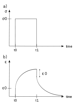
When subjected to a step constant stress, viscoelastic materials experience a time-dependent increase in strain. This phenomenon is known as viscoelastic creep.
At a time t0, a viscoelastic material is loaded with a constant stress that is maintained for a sufficiently long time period. The material responds to the stress with a strain that increases until the material ultimately fails. When the stress is maintained for a shorter time period, the material undergoes an initial strain until a time t1 at which the stress is relieved, at which time the strain immediately decreases (discontinuity) then continues decreasing gradually to a residual strain.
Viscoelastic creep data can be presented in one of two ways. Total strain can be plotted as a function of time for a given temperature or temperatures. Below a critical value of applied stress, a material may exhibit linear viscoelasticity. Above this critical stress, the creep rate grows disproportionately faster. The second way of graphically presenting viscoelastic creep in a material is by plotting the creep modulus (constant applied stress divided by total strain at a particular time) as a function of time.[16] Below its critical stress, the viscoelastic creep modulus is independent of stress applied. A family of curves describing strain versus time response to various applied stress may be represented by a single viscoelastic creep modulus versus time curve if the applied stresses are below the material's critical stress value.
Additionally, the molecular weight of the polymer of interest is known to affect its creep behavior. The effect of increasing molecular weight tends to promote secondary bonding between polymer chains and thus make the polymer more creep resistant. Similarly, aromatic polymers are even more creep resistant due to the added stiffness from the rings. Both molecular weight and aromatic rings add to polymers' thermal stability, increasing the creep resistance of a polymer.[17]
Both polymers and metals can creep. Polymers experience significant creep at temperatures above ca. –200 °C; however, there are three main differences between polymeric and metallic creep.[18]
Polymers show creep basically in two different ways. At typical work loads (5 up to 50%) ultra high molecular weight polyethylene (Spectra, Dyneema) will show time-linear creep, whereas polyester or aramids (Twaron, Kevlar) will show a time-logarithmic creep.
Creep of concrete
The creep of concrete, which originates from the calcium silicate hydrates (C-S-H) in the hardened Portland cement paste (which is the binder of mineral aggregates), is fundamentally different from the creep of metals as well as polymers. Unlike the creep of metals, it occurs at all stress levels and, within the service stress range, is linearly dependent on the stress if the pore water content is constant. Unlike the creep of polymers and metals, it exhibits multi-months aging, caused by chemical hardening due to hydration which stiffens the microstructure, and multi-year aging, caused by long-term relaxation of self-equilibrated micro-stresses in the nano-porous microstructure of the C-S-H. If concrete is fully dried it does not creep, though it is difficult to dry concrete fully without severe cracking.
Applications
Though mostly due to the reduced yield strength at higher temperatures, the collapse of the World Trade Center was due in part to creep from increased temperature operation.[19]
The creep rate of hot pressure-loaded components in a nuclear reactor at power can be a significant design constraint, since the creep rate is enhanced by the flux of energetic particles.
Creep in epoxy anchor adhesive was blamed for the Big Dig tunnel ceiling collapse in Boston, Massachusetts that occurred in July 2006.[20]
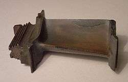
The design of tungsten light bulb filaments attempts to reduce creep deformation. Sagging of the filament coil between its supports increases with time due to the weight of the filament itself. If too much deformation occurs, the adjacent turns of the coil touch one another, causing an electrical short and local overheating, which quickly leads to failure of the filament. The coil geometry and supports are therefore designed to limit the stresses caused by the weight of the filament, and a special tungsten alloy with small amounts of oxygen trapped in the crystallite grain boundaries is used to slow the rate of Coble creep.
Creep can cause gradual cut-through of wire insulation, especially when stress is concentrated by pressing insulated wire against a sharp edge or corner. Special creep-resistant insulations such as Kynar (polyvinylidene fluoride) are used in wirewrap applications to resist cut-through due to the sharp corners of wire wrap terminals. Teflon insulation is resistant to elevated temperatures and has other desirable properties, but is notoriously vulnerable to cold-flow cut-through failures caused by creep.
In steam turbine power plants, pipes carry steam at high temperatures (566 °C (1,051 °F)) and pressures (above 24.1 MPa or 3500 psi). In jet engines, temperatures can reach up to 1,400 °C (2,550 °F) and initiate creep deformation in even advanced-design coated turbine blades. Hence, it is crucial for correct functionality to understand the creep deformation behavior of materials.
Creep deformation is important not only in systems where high temperatures are endured such as nuclear power plants, jet engines and heat exchangers, but also in the design of many everyday objects. For example, metal paper clips are stronger than plastic ones because plastics creep at room temperatures. Aging glass windows are often erroneously used as an example of this phenomenon: measurable creep would only occur at temperatures above the glass transition temperature around 500 °C (932 °F). While glass does exhibit creep under the right conditions, apparent sagging in old windows may instead be a consequence of obsolete manufacturing processes, such as that used to create crown glass, which resulted in inconsistent thickness.[21][22]
Fractal geometry, using a deterministic Cantor structure, is used to model the surface topography, where recent advancements in thermoviscoelastic creep contact of rough surfaces are introduced. Various viscoelastic idealizations are used to model the surface materials, for example, Maxwell, Kelvin-Voigt, Standard Linear Solid and Jeffrey media.[23]
Nimonic 75 has been certified by the European Union as a standard creep reference material.[24]
The practice of tinning stranded wires to facilitate the process of connecting the wire to a screw terminal, though having been prevalent and considered standard practice for quite a while, has been discouraged by professional electricians,[25] owing to the fact that the solder is likely to creep under the pressure excerted on the tinned wire end by the screw of the terminal, causing the joint to lose tension and hence create a loose contact over time. The accepted practice when connecting stranded wire to a screw terminal is to use a wire ferrule on the end of the wire.
Preventing creep
Creep resistance can be influenced by many factors such as diffusivity, precipitate and grain size.
Take metal as an example, to improve creep resistance, it is obvious that diffusion rate should be reduced. And due to the fact that diffusion activation energy is proportional to absolute melting temperature, for a specific creep temperature, materials with higher melting temperature will be preferred. Diffusivity can also be influenced by material classes. Body-centered cubic metals, which are not as close packed as face-centered cubic metals and has more frequently vibrating atoms, consequently has higher diffusion coefficients. That’s the reason why bcc materials are less creep resistant in high temperatures.
What’s more, when the primary creep mechanism is dislocation, shear modulus will play an important role. In this situation, materials with higher shear modulus, which are harder to deform, will be more creep resistant. However, modulus changes of different materials are much less than diffusivity changes, indicating that modulus strengthening is not as efficient as diffusion decrease in creep resistance.
In addition, microstructures, or in this case, grain sizes and particles at grain boundaries, are also correlated with creep resistance. When diffusion creep dominates, increasing grain sizes can significantly reduce creep rate because the rate is proportional to (diameter)−2 in NH creep and (diameter)−3 in Coble creep. The second-phase intergranular particles, on the other hand, will prevent the grain boundaries from sliding.[4]
Thus, we can conclude that there are three general ways to prevent creep in metal. One way is to use higher melting point metals. The second way is to use materials with greater grain size. The third way is to use alloying.
Creep of superalloys
Materials operating in high-performance systems, such as jet engines, often reach extreme temperatures surpassing 1200 °C, which causes creep to be a serious issue. Superalloys based on Co, Ni, and Fe are capable of being engineered to be highly resistant to creep, and have thus arisen as an ideal material in high-temperature environments. As an example, Ni-base alloys modeled after the Ni-Al system, known as γ-γ’ alloys are even resistant to dislocation creep. The γ is the main fcc matrix, while the γ’ is the precipitate-phase of Ni3(Al, Ti), which adds particle strengthening. Solute elements added, e.g., Ta, W, Mo, Fe, Cr, and Co, contribute solid-solution hardening, and are often reacted with carbon to form carbide particles that deposit at grain boundaries, and thus inhibit grain boundary sliding.[4]
Recently, there are also some developments in creep of superalloys. In 2017, Weili Ren at el. exended the creep life of Ni-based single crystal superalloy significantly by adding a static magnetic field in solidification process. By using this method, the composition distribution becomes more homogenous in several scales, making the lattice in γ’ phase more coherent with the lattice in matrix. As a result, dislocation quantitiy is reduced during the creep. What’s more, the size of γ’ as well as other precipitation is also decreased, which can be proved by observation of decrease in crack numbers and raft thickness near fractures. Although the magnetic field will damage the integrity of single crystal, this method shows a new routine to control microstructure and mechanical properties in superalloys and still benefits the creep lifetime.[26]
Another research done by Te-Kang Tsao at el. in 2017 is about creep behaviors of a novel high entropy superalloy(HESA). The results of creep at 982 °C show that HESA, which is dominated by tertiary creep, has comparable creep behaviors as some NI-based superalloys. The high creep resistance is primarily due to low stacking-fault energy in matrix, high anti-phase boundary energy in precipitates as well as thermally stable microstructure. This research is the first to discuss tensile creep on full scale specimens of high entropy alloys, which shows the potential of HESA at high temperature application.[27]
See also
References
- ↑ "Rheology of Ice". Archived from the original on 2007-06-17. Retrieved 2008-10-16.
- ↑ Ashby, Michael (2014). Materials. Oxford: Elsevier. p. 336. ISBN 978-0-08-097773-7.
- ↑ "Deformation & Flow | Mechanics". Encyclopedia Britannica. Retrieved 2017-03-29.
- 1 2 3 4 Courtney, Thomas H. (2005). Mechanical behavior of materials. Waveland Press. ISBN 9781577664253. OCLC 894800884.
- ↑ "Thermal Creep". NADCA Design. Retrieved 2017-03-29.
- ↑ "Creep and Stress Rupture" (PDF). NC State University. 2017-03-29.
- 1 2 Mohamed, F. A.; Murty, K. L.; Morris, J. W. (April 1973). "Harper–dorn creep in al, pb, and sn". Metallurgical Transactions. 4 (4): 935–940. doi:10.1007/BF02645593.
- ↑ Kassner, M.E; Pérez-Prado, M.-T (January 2000). "Five-power-law creep in single phase metals and alloys". Progress in Materials Science. 45 (1): 1–102. doi:10.1016/S0079-6425(99)00006-7.
- ↑ Paufler, P. (October 1986). "ISBN". Crystal Research and Technology. 21 (10): 1338–1338. doi:10.1002/crat.2170211021. templatestyles stripmarker in
|title=at position 260 (help) - ↑ Mohamed, Farghalli A.; Ginter, Timothy J. (October 1982). "On the nature and origin of Harper–Dorn creep". Acta Metallurgica. 30 (10): 1869–1881. doi:10.1016/0001-6160(82)90027-X.
- ↑ Courtney, Thomas H. (2000). Mechanical behavior of materials (2nd ed.). Boston: McGraw Hill. ISBN 0070285942. OCLC 41932585.
- ↑ Hull, D.; Rimmer, D.E. (2010). "The growth of grain-boundary voids under stress". he Philosophical Magazine: A Journal of Theoretical Experimental and Applied Physics. 4:42: 673–687. doi:10.1080/14786435908243264.
- ↑ Lenel, F. V.; Ansell, G. S. (1966). Modern Developments in Powder Metallurgy. Springer, Boston, MA. pp. 281–296. doi:10.1007/978-1-4684-7706-1_15. ISBN 9781468477085.
- 1 2 Wilkinson, D.S.; Ashby, M.F. (November 1975). "Pressure sintering by power law creep". Acta Metallurgica. 23 (11): 1277–1285. doi:10.1016/0001-6160(75)90136-4. ISSN 0001-6160.
- ↑ Ratzker, Barak; Sokol, Maxim; Kalabukhov, Sergey; Frage, Nachum (2016-06-20). "Creep of Polycrystalline Magnesium Aluminate Spinel Studied by an SPS Apparatus". Materials. 9 (6): 493. doi:10.3390/ma9060493. PMC 5456765. PMID 28773615.
- ↑ Rosato, D. V. et al. (2001) Plastics Design Handbook. Kluwer Academic Publishers. pp. 63–64. ISBN 0792379802.
- ↑ M. A. Meyers; K. K. Chawla (1999). Mechanical Behavior of Materials. Cambridge University Press. p. 573. ISBN 978-0-521-86675-0.
- ↑ McCrum, N.G.; Buckley, C.P.; Bucknall, C.B. (2003). Principles of Polymer Engineering. Oxford Science Publications. ISBN 0-19-856526-7.
- ↑ Zdeněk Bažant and Yong Zhu, "Why Did the World Trade Center Collapse?—Simple Analysis", Journal of Engineering Mechanics, January 2002
- ↑ "Ceiling Collapse in the Interstate 90 Connector Tunnel". National Transportation Safety Board. Washington, D.C.: NTSB. July 10, 2007. Retrieved 2 December 2016.
- ↑ Lakes, Roderic S. (1999). Viscoelastic Solids. p. 476. ISBN 0-8493-9658-1.
- ↑ "Is glass liquid or solid?". University of California, Riverside. Retrieved 2008-10-15.
- ↑ Osama Abuzeid; Anas Al-Rabadi; Hashem Alkhaldi (2011). "Recent advancements in fractal geometric-based nonlinear time series solutions to the micro-quasistatic thermoviscoelastic creep for rough surfaces in contact". Mathematical Problems in Engineering. 2011. doi:10.1155/2011/691270. 691270.
- ↑ Gould, D.; Loveday, M.S. (1990). "The certification of nimonic 75 alloy as a creep reference material — CRM 425" (PDF). Luxembourg: Office for Official Publications of the European Communities. ISBN 92-826-1742-4. Archived from the original (PDF) on 2015-04-03.
- ↑ IPC J-STD-001 Rev. E, Requirements for Soldered Electrical and. Electronic Assemblies
- ↑ Ren, Weili; Niu, Chunlin; Ding, Biao; Zhong, Yunbo; Yu, Jianbo; Ren, Zhongming; Liu, Wenqing; Ren, Liangpu; Liaw, Peter K. (2018-01-23). "Improvement in creep life of a nickel-based single-crystal superalloy via composition homogeneity on the multiscales by magnetic-field-assisted directional solidification". Scientific Reports. 8 (1). doi:10.1038/s41598-018-19800-5. ISSN 2045-2322.
- ↑ Tsao, Te-Kang; Yeh, An-Chou; Kuo, Chen-Ming; Kakehi, Koji; Murakami, Hideyuki; Yeh, Jien-Wei; Jian, Sheng-Rui (2017-10-04). "The High Temperature Tensile and Creep Behaviors of High Entropy Superalloy". Scientific Reports. 7 (1). doi:10.1038/s41598-017-13026-7. ISSN 2045-2322.
Further reading
- Ashby, Michael F.; Jones, David R. H. (1980). Engineering Materials 1: An Introduction to their Properties and Applications. Pergamon Press. ISBN 0-08-026138-8.
- Frost, Harold J.; Ashby, Michael F. (1982). Deformation-Mechanism Maps: The Plasticity and Creep of Metals and Ceramics. Pergamon Press. ISBN 0-08-029337-9.
- Turner, S (2001). Creep of Polymeric Materials. Oxford: Elsevier Science Ltd. pp. 1813–1817. ISBN 0-08-043152-6.