Attitude indicator
The attitude indicator (AI), formerly known as the gyro horizon or artificial horizon, is a flight instrument that informs the pilot of the aircraft orientation relative to Earth's horizon, and gives an immediate indication of the smallest orientation change. The miniature aircraft and horizon bar mimic the relationship of the aircraft relative to the actual horizon. [1][2] It is a primary instrument for flight in instrument meteorological conditions. [3][4]
Use
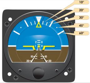
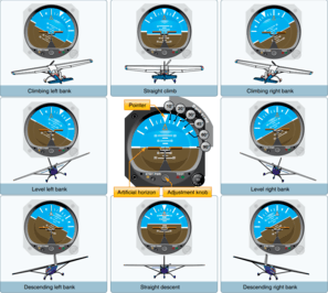
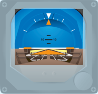
The essential components of the AI include a symbolic miniature aircraft mounted so that it appears to be flying relative to the horizon. An adjustment knob, to account for the pilot's line of vision, moves the aircraft up and down to align it against the horizon bar. The top half of the instrument is blue to represent the sky, while the bottom half is brown to represent the ground. The bank index at the top shows the aircraft angle of bank. Reference lines in the middle indicate the degree of pitch, up or down, relative to the horizon.[2][1]
Most Russian-built aircraft have a somewhat different design. The background display is colored as in a Western instrument, but moves up and down only to indicate pitch. A symbol representing the aircraft (which is fixed in a Western instrument) rolls left or right to indicate bank angle.[5] A proposed hybrid version of the Western and Russian systems that would be more intuitive, never caught on.[6]
Operation
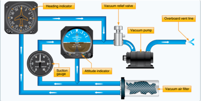
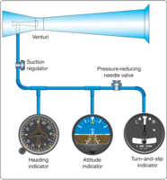
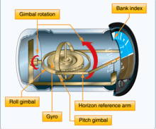
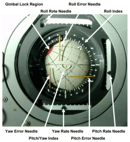
The heart of the AI is a gyroscope (gyro) that spins at high speed, from either an electric motor, or through the action of a stream of air pushing on rotor vanes placed along its periphery. The stream of air is provided by a vacuum system, driven by a vacuum pump, or a venturi. Air passing through the narrowest portion of a venturi has lower air pressure through Bernoulli's Principle. The gyro is mounted in a double gimbal, which allows the aircraft to pitch and roll as the gyro stays vertically upright. An self-erecting mechanism, actuated by gravity, counteracts any precession due to bearing friction. It may take a few minutes for the erecting mechanism to bring the gyros to a vertical upright position after the aircraft engine is first powered up.[2][1][7]
Attitude indicators have mechanisms that keep the instrument level with respect to the direction of gravity.[8] The instrument may develop small errors, in pitch or bank during extended periods of acceleration, deceleration, turns, or due to the earth curving underneath the plane on long trips. To start with, they often have slightly more weight in the bottom, so that when the aircraft is resting on the ground they will hang level and therefore they will be level when started. But once they are started, that pendulous weight in the bottom will not pull them level if they are out of level, but instead its pull will cause the gyro to precess. In order to let the gyro very slowly orient itself to the direction of gravity while in operation, the typical vacuum powered gyro has small pendulums on the rotor casing that partially cover air holes. When the gyro is out of level with respect to the direction of gravity, the pendulums will swing in the direction of gravity and either uncover or cover the holes, such that air is allowed or prevented from jetting out of the holes, and thereby applying a small force to orient the gyro towards the direction of gravity. Electric powered gyros may have different mechanisms to achieve a similar effect.[9]
Older AIs were limited in the amount of pitch or roll that they would tolerate. Exceeding these limits would cause the gyro to tumble as the gyro housing contacted the gimbals, causing a precession force. Preventing this required a caging mechanism to lock the gyro if the pitch exceed 60° and the roll exceeded 100°. Modern AIs don't have this limitation and don't require a caging mechanism.[2][1]
Flight Director Attitude Indicator

Attitude indicators are also used on manned spacecraft and are called Flight Director Attitude Indicators (FDAI), where they indicate the craft's yaw angle (nose left or right), pitch (nose up or down), roll, and orbit relative to a fixed-space inertial reference frame from an Inertial Measurement Unit (IMU).[10] The FDAI can be configured to use known positions relative to Earth or the stars, so that the engineers, scientists and astronauts can communicate the relative position, attitude, and orbit of the craft. [11][12]
Attitude and Heading Reference Systems
Attitude and Heading Reference Systems (AHRS) are able to provide three-axis information based on ring laser gyroscopes, that can be shared with multiple devices in the aircraft, such as "glass cockpit" primary flight displays (PFDs). Rather than using a spinning gyroscope, modern AHRS use solid-state electronics, low-cost inertial sensors, rate gyros, and magnetometers.[2]:8-20[1]:5-22
With most AHRS systems, if an aircraft's AIs have failed there will be a standby AI located in the center of the instrument panel, where other standby basic instruments such as the airspeed indicator and altimeter are also available. These mostly mechanical standby instruments may be available even if the electronic flight instruments fail, though the standby attitude indicator may be electrically driven and will, after a short time, fail if its electrical power fails.[13]
Attitude Direction Indicator

The Attitude Direction Indicator (ADI), or Flight Director Indicator (FDI), is an AI integrated with a Flight Director System (FDS). The ADI incorporates a computer that receives information from the navigation system, such as the AHRS, and processes this information to provide the pilot with a 3-D flight trajectory cue to maintain a desired path. The cue takes the form of V steering bars. The aircraft is represented by a delta symbol and the pilot flies the aircraft so that the delta symbol is placed within the V steering bars.[1]:5-23,5-24

See also
References
- 1 2 3 4 5 6 Instrument Flying Handbook, FAA-H-8083-15B (PDF). U.S. Dept. of Transportation, FAA. 2012. p. 5-17,5-19.
- 1 2 3 4 5 Pilot's Handbook of Aeronautical Knowledge, FAA-H-8083-25B (PDF). U.S. Dept. of Transportation, FAA. 2016. p. 8-16,8-18,8-19.
- ↑ Jeppesen, A Boeing Company (2007). Guided Flight Discovery Private PilotJe. Jeppesen. pp. 2–66. ISBN 978-0-88487-429-4.
- ↑ http://www.faa.gov/regulations_policies/handbooks_manuals/aircraft/amt_airframe_handbook/media/ama_ch10.pdf Aircraft Instrument Systems page 10-56
- ↑ Learmount, David (2009-02-09), "Which way is up for Eastern and Western artificial horizons?", flightglobal.com, archived from the original on October 29, 2014
- ↑ Safety expert proposes low-cost loss of control fixes , FlightGlobal, 2011-03-04
- ↑ Federal Aviation Administration (FAA). "Chapter 10. Aircraft Instrument Systems" (PDF). Archived from the original (PDF) on 2014-03-01.
- ↑ murphy, alan. "4-4". www.faatest.com. Retrieved 22 March 2018.
- ↑ murphy, alan. "4-5". www.faatest.com. Retrieved 22 March 2018.
- ↑ "Flight-Director/Atitude Indicator". www.hq.nasa.gov. Retrieved 2016-12-01.
- ↑ "Apollo Flight Journal - Apollo Operations Handbook. Volume 1". history.nasa.gov. Archived from the original on 2015-12-24. Retrieved 2016-12-01.
- ↑ "Apollo Guidance, Navigation, and Control (GNC) Hardware Overview" (PDF). NASA Technical Reports Server. NASA. Retrieved 12 October 2018.
- ↑ "NTSB Safety Recommendation". 2010-11-08.