Aircraft principal axes

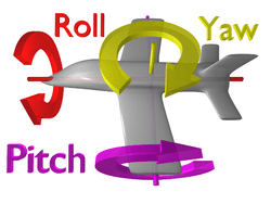
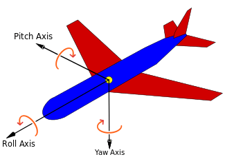
An aircraft in flight is free to rotate in three dimensions: yaw, nose left or right about an axis running up and down; pitch, nose up or down about an axis running from wing to wing; and roll, rotation about an axis running from nose to tail. The axes are alternatively designated as vertical, transverse, and longitudinal respectively. These axes move with the vehicle and rotate relative to the Earth along with the craft. These definitions were analogously applied to spacecraft when the first manned spacecraft were designed in the late 1950s.
These rotations are produced by torques (or moments) about the principal axes. On an aircraft, these are intentionally produced by means of moving control surfaces, which vary the distribution of the net aerodynamic force about the vehicle's center of gravity. Elevators (moving flaps on the horizontal tail) produce pitch, a rudder on the vertical tail produces yaw, and ailerons (flaps on the wings that move in opposing directions) produce roll. On a spacecraft, the moments are usually produced by a reaction control system consisting of small rocket thrusters used to apply asymmetrical thrust on the vehicle.
Principal axes

- Normal axis, or yaw axis — an axis drawn from top to bottom, and perpendicular to the other two axes. Parallel to the fuselage station.
- Transverse axis, lateral axis, or pitch axis — an axis running from the pilot's left to right in piloted aircraft, and parallel to the wings of a winged aircraft. Parallel to the buttock line.
- Longitudinal axis, or roll axis — an axis drawn through the body of the vehicle from tail to nose in the normal direction of flight, or the direction the pilot faces. Parallel to the waterline.
Normally, these axes are represented by the letters X, Y and Z in order to compare them with some reference frame, usually named x, y, z. Normally, this is made in such a way that the X is used for the longitudinal axis, but there are other possibilities to do it.
Vertical axis (yaw)

The yaw axis has its origin at the center of gravity and is directed towards the bottom of the aircraft, perpendicular to the wings and to the fuselage reference line. Motion about this axis is called yaw. A positive yawing motion moves the nose of the aircraft to the right.[1][2] The rudder is the primary control of yaw.[3]
Transverse axis (pitch)
The pitch axis (also called transverse or lateral axis[4]) has its origin at the center of gravity and is directed to the right, parallel to a line drawn from wingtip to wingtip. Motion about this axis is called pitch. A positive pitching motion raises the nose of the aircraft and lowers the tail. The elevators are the primary control of pitch.[3]
Longitudinal axis (roll)
The roll axis (or longitudinal axis[4]) has its origin at the center of gravity and is directed forward, parallel to the fuselage reference line. Motion about this axis is called roll. An angular displacement about this axis is called bank.[3] A positive rolling motion lifts the left wing and lowers the right wing. The pilot rolls by increasing the lift on one wing and decreasing it on the other. This changes the bank angle. The ailerons are the primary control of bank. The rudder also has a secondary effect on bank.[5]
Relationship with other systems of axes
These axes are related to the principal axes of inertia, but are not the same. They are geometrical symmetry axes, regardless of the mass distribution of the aircraft.
In aeronautical and aerospace engineering intrinsic rotations around these axes are often called Euler angles, but this conflicts with existing usage elsewhere. The calculus behind them is similar to the Frenet–Serret formulas. Performing a rotation in an intrinsic reference frame is equivalent to right-multiplying its characteristic matrix (the matrix that has the vector of the reference frame as columns) by the matrix of the rotation.
History
The first aircraft to demonstrate active control about all three axes was the Wright brothers' 1902 glider.[6]
See also
References
- ↑ "Yaw axis". Retrieved 2008-07-31.
- ↑ "Specialty Definition: YAW AXIS". Retrieved 2008-07-31.
- 1 2 3 Clancy, L.J. (1975) Aerodynamics Pitman Publishing Limited, London ISBN 0-273-01120-0, Section 16.6
- 1 2 "MISB Standard 0601" (PDF). Motion Imagery Standards Board (MISB). Retrieved 1 May 2015. Also at File:MISB Standard 0601.pdf.
- ↑ FAA (2004). Airplane Flying Handbook. Washington D.C.:U.S. Department of Transportation, Federal Aviation Administration, ch 4, p 2, FAA-8083-3A.
- ↑ "Aircraft rotations". Archived from the original on 4 July 2008. Retrieved 2008-08-04.