Railgun
A railgun is a linear motor device, typically designed as a weapon, that uses electromagnetic force to launch high velocity projectiles. The projectile normally does not contain explosives, instead relying on the projectile's high speed and kinetic energy to inflict damage.[2] The railgun uses a pair of parallel conductors (rails), along which a sliding armature is accelerated by the electromagnetic effects of a current that flows down one rail, into the armature and then back along the other rail. It is based on principles similar to those of the homopolar motor.[3]
As of 2020, railguns have been researched as weapons utilising electromagnetic forces to impart a very high kinetic energy to a projectile (e.g. APFSDS) rather than using conventional propellants. While explosive-powered military guns cannot readily achieve a muzzle velocity of more than ≈2 km/s, railguns can readily exceed 3 km/s. For a similar projectile, the range of railguns may exceed that of conventional guns. The destructive force of a projectile depends on its kinetic energy at the point of impact and due to the potentially high velocity of a railgun-launched projectile, their destructive force may be much greater than conventionally launched projectiles of the same size. The absence of explosive propellants or warheads to store and handle, as well as the low cost of projectiles compared to conventional weaponry, come as additional advantages.[4]
Notwithstanding the above advantages, railguns are still very much at the research stage after decades of R&D, and it remains to be seen whether or not they will ever be deployed as practical military weapons. Any trade-off analysis between electromagnetic (EM) propulsion systems and chemical propellants for weapons applications must also factor in its durability, availability and economics, as well as the novelty, bulkiness, high energy demand and complexity of the pulsed power supplies that are needed for electromagnetic launcher systems.
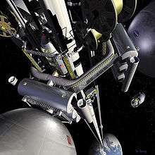
In addition to military applications, NASA has proposed to use a railgun to launch "wedge-shaped aircraft with scramjets" to high-altitude at Mach 10, where they will then fire a small payload into orbit using conventional rocket propulsion.[5] The extreme g-forces involved with direct railgun ground-launch to space may restrict the usage to only the sturdiest of payloads. Alternatively, very long rail systems may be used to reduce the required launch acceleration.[6]
Basics
The railgun in its simplest form differs from a traditional electric motor[7] in that no use is made of additional field windings (or permanent magnets). This basic configuration is formed by a single loop of current and thus requires high currents (e.g., of order one million amperes) to produce sufficient accelerations (and muzzle velocities). A relatively common variant of this configuration is the augmented railgun in which the driving current is channelled through additional pairs of parallel conductors, arranged to increase ('augment') the magnetic field experienced by the moving armature.[8] These arrangements reduce the current required for a given acceleration. In electric motor terminology, augmented railguns are usually series-wound configurations. Some railguns also use strong neodymium magnets with the field perpendicular to the current flow to increase the force on the projectile.
The armature may be an integral part of the projectile, but it may also be configured to accelerate a separate, electrically isolated or non-conducting projectile. Solid, metallic sliding conductors are often the preferred form of railgun armature but plasma or 'hybrid' armatures can also be used.[9] A plasma armature is formed by an arc of ionised gas that is used to push a solid, non-conducting payload in a similar manner to the propellant gas pressure in a conventional gun. A hybrid armature uses a pair of plasma contacts to interface a metallic armature to the gun rails. Solid armatures may also 'transition' into hybrid armatures, typically after a particular velocity threshold is exceeded.
A railgun requires a pulsed DC power supply.[10] For potential military applications, railguns are usually of interest because they can achieve much greater muzzle velocities than guns powered by conventional chemical propellants. Increased muzzle velocities with better aerodynamically streamlined projectiles can convey the benefits of increased firing ranges while, in terms of target effects, increased terminal velocities can allow the use of kinetic energy rounds incorporating hit-to-kill guidance, as replacements for explosive shells. Therefore, typical military railgun designs aim for muzzle velocities in the range of 2,000–3,500 m/s (4,500–7,800 mph; 7,200–12,600 km/h) with muzzle energies of 5–50 megajoules (MJ). For comparison, 50 MJ is equivalent to the kinetic energy of a school bus weighing 5 metric tons, travelling at 509 km/h (316 mph; 141 m/s).[11] For single loop railguns, these mission requirements require launch currents of a few million amperes, so a typical railgun power supply might be designed to deliver a launch current of 5 MA for a few milliseconds. As the magnetic field strengths required for such launches will typically be approximately 10 tesla (100 kilogauss), most contemporary railgun designs are effectively air-cored, i.e., they do not use ferromagnetic materials such as iron to enhance the magnetic flux. However, if the barrel is made of a magnetically permeable material, the magnetic field strength increases due to the increase in permeability (μ = μ0*μr, where μ is the effective permeability, μ0 is the permeability constant and μr is the relative permeability of the barrel). This automatically increases the force.
Railgun velocities generally fall within the range of those achievable by two-stage light-gas guns; however, the latter are generally only considered to be suitable for laboratory use, while railguns are judged to offer some potential prospects for development as military weapons. Another light gas gun, the Combustion Light Gas Gun in a 155 mm prototype form was projected to achieve 2500 m/s with a .70 caliber barrel. In some hypervelocity research projects, projectiles are 'pre-injected' into railguns, to avoid the need for a standing start, and both two-stage light-gas guns and conventional powder guns have been used for this role. In principle, if railgun power supply technology can be developed to provide safe, compact, reliable, combat survivable, and lightweight units, then the total system volume and mass needed to accommodate such a power supply and its primary fuel can become less than the required total volume and mass for a mission equivalent quantity of conventional propellants and explosive ammunition. Arguably such technology has been matured with the introduction of the Electromagnetic Aircraft Launch System (EMALS) (albeit that railguns require much higher system powers, because roughly similar energies must be delivered in a few milliseconds, as opposed to a few seconds). Such a development would then convey a further military advantage in that the elimination of explosives from any military weapons platform will decrease its vulnerability to enemy fire.
History
The concept of the railgun was first introduced by French inventor Andre Louis Octave Fauchon-Villeplee, who created a small working model in 1917 with the help of the Société anonyme des accumulateurs Tudor (now Tudor Batteries).[12][13] During World War I, the Director of Inventions at the Ministry of Armaments, Jules-Louis Brenton, commissioned Fauchon-Villeplee to develop a 30-mm to 50-mm electric cannon on July 25, 1918 after delegates from the Commission des Inventions witnessed test trials of the working model in 1917. However, the project was abandoned once World War I ended later that year on November 3, 1918.[13] Fauchon-Villeplee filed for a US patent on 1 April 1919, which was issued in July 1922 as patent no. 1,421,435 "Electric Apparatus for Propelling Projectiles".[14] In his device, two parallel busbars are connected by the wings of a projectile, and the whole apparatus surrounded by a magnetic field. By passing current through busbars and projectile, a force is induced which propels the projectile along the bus-bars and into flight.[15]
In 1923, Russian scientist A. L. Korol’kov detailed his criticisms of Fauchon-Villeplee's design, arguing against some of the claims that Fauchon-Villeplee made about the advantages of his invention. Korol’kov eventually concluded that while the construction of a long-range electric gun was within the realm of possibility, the practical application of Fauchon-Villeplee's railgun was hindered by its enormous electric energy consumption and its need for a special electric generator of considerable capacity to power it.[13][16]
In 1944, during World War II, Joachim Hänsler of Nazi Germany's Ordnance Office proposed the first theoretically viable railgun.[13][17] By late 1944, the theory behind his electric anti-aircraft gun had been worked out sufficiently to allow the Luftwaffe's Flak Command to issue a specification, which demanded a muzzle velocity of 2,000 m/s (4,500 mph; 7,200 km/h; 6,600 ft/s) and a projectile containing 0.5 kg (1.1 lb) of explosive. The guns were to be mounted in batteries of six firing twelve rounds per minute, and it was to fit existing 12.8 cm FlaK 40 mounts. It was never built. When details were discovered after the war it aroused much interest and a more detailed study was done, culminating with a 1947 report which concluded that it was theoretically feasible, but that each gun would need enough power to illuminate half of Chicago.[15]
During 1950, Sir Mark Oliphant, an Australian physicist and first director of the Research School of Physical Sciences at the new Australian National University, initiated the design and construction of the world's largest (500 megajoule) homopolar generator.[18] This machine was operational from 1962 and was later used to power a large-scale railgun that was used as a scientific experiment.[19]
In 1980, the Ballistic Research Laboratory (later consolidated to form the U.S. Army Research Laboratory) began a long-term program of theoretical and experimental research on railguns. The work was conducted predominantly at the Aberdeen Proving Ground, and much of the early research drew inspiration from the railgun experiments performed by the Australian National University.[20][21] Topics of research included plasma dynamics,[22] electromagnetic fields,[23] telemetry,[24] and current and heat transport.[25] While military research into railgun technology in the United States ensued continuously in the following decades, the direction and focus that it took shifted dramatically with major changes in funding levels and the needs of different government agencies. In 1984, the formation of the Strategic Defense Initiative Organization caused research goals to shift toward establishing a constellation of satellites to intercept intercontinental ballistic missiles. As a result, the U.S. military focused on developing small guided projectiles that could withstand the high-G launch from ultra-high velocity plasma armature railguns. But after the publication of an important Defense Science Board study in 1985, the U.S. Army, Marine Corps, and DARPA were assigned to develop anti-armor, electromagnetic launch technologies for mobile ground combat vehicles.[26] In 1990, the U.S. Army collaborated with the University of Texas at Austin to establish the Institute for Advanced Technology (IAT), which focused on research involving solid and hybrid armatures, rail-armature interactions, and electromagnetic launcher materials.[27] The facility became the Army's first Federally Funded Research and Development Center and housed a few of the Army's electromagnetic launchers, such as the Medium Caliber Launcher.[26][28]
Since 1993 the British and American governments have collaborated on a railgun project at the Dundrennan Weapons Testing Centre that culminated in the 2010 test where BAE Systems fired a 3.2 kg (7 pound) projectile at 18.4-megajoules [3,390 m/s (7,600 mph; 12,200 km/h; 11,100 ft/s)].[29] In 1994, India's DRDO's Armament Research and Development Establishment developed a railgun with a 240 kJ, low inductance capacitor bank operating at 5 kV power able to launch projectiles of 3–3.5 g weight to a velocity of more than 2,000 m/s (4,500 mph; 7,200 km/h; 6,600 ft/s).[30] In 1995, the Center for Electromagnetics at the University of Texas at Austin designed and developed a rapid-fire railgun launcher called the Cannon-Caliber Electromagnetic Gun. The launcher prototype was later tested at the U.S. Army Research Laboratory, where it demonstrated a breech efficiency over 50 percent.[31][32]
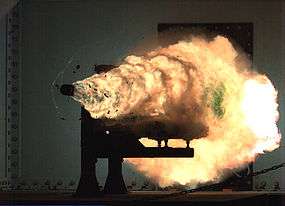
In 2010, the United States Navy tested a BAE Systems-designed compact-sized railgun for ship emplacement that accelerated a 3.2 kg (7 pound) projectile to hypersonic velocities of approximately 3,390 m/s (7,600 mph; 12,200 km/h; 11,100 ft/s), or about Mach 10, with 18.4 MJ of kinetic energy. It was the first time in history that such levels of performance were reached.[29][33] They gave the project the motto "Velocitas Eradico", Latin for "I, [who am] speed, eradicate"—or in the vernacular, "Speed Kills". An earlier railgun of the same design (32-megajoules) resides at the Dundrennan Weapons Testing Centre in the United Kingdom.[34]
Low power, small scale railguns have also made popular college and amateur projects. Several amateurs actively carry out research on railguns.[35][36] No practical railgun weapon has been developed or is expected in the near-future as of January 2020.
Design
Theory
A railgun consists of two parallel metal rails (hence the name). At one end, these rails are connected to an electrical power supply, to form the breech end of the gun. Then, if a conductive projectile is inserted between the rails (e.g. by insertion into the breech), it completes the circuit. Electrons flow from the negative terminal of the power supply up the negative rail, across the projectile, and down the positive rail, back to the power supply.[37]
This current makes the railgun behave as an electromagnet, creating a magnetic field inside the loop formed by the length of the rails up to the position of the armature. In accordance with the right-hand rule, the magnetic field circulates around each conductor. Since the current is in the opposite direction along each rail, the net magnetic field between the rails (B) is directed at right angles to the plane formed by the central axes of the rails and the armature. In combination to all with the current (I) in the armature, this produces a Lorentz force which accelerates the projectile along the rails, always out of the loop (regardless of supply polarity) and away from the power supply, towards the muzzle end of the rails. There are also Lorentz forces acting on the rails and attempting to push them apart, but since the rails are mounted firmly, they cannot move.
By definition, if a current of one ampere flows in a pair of ideal infinitely long parallel conductors that are separated by a distance of one meter, then the magnitude of the force on each meter of those conductors will be exactly 0.2 micro-newtons. Furthermore, in general, the force will be proportional to the square of the magnitude of the current and inversely proportional to the distance between the conductors. It also follows that, for railguns with projectile masses of a few kg and barrel lengths of a few m, very large currents will be required to accelerate projectiles to velocities of the order of 1000 m/s.
A very large power supply, providing on the order of one million amperes of current, will create a tremendous force on the projectile, accelerating it to a speed of many kilometres per second (km/s). Although these speeds are possible, the heat generated from the propulsion of the object is enough to erode the rails rapidly. Under high-use conditions, current railguns would require frequent replacement of the rails, or to use a heat-resistant material that would be conductive enough to produce the same effect. At this time it is generally acknowledged that it will take major breakthroughs in materials science and related disciplines to produce high-powered railguns capable of firing more than a few shots from a single set of rails. The barrel must withstand these conditions for up to several rounds per minute for thousands of shots without failure or significant degradation. These parameters are well beyond the state of the art in materials science.[38]
Mathematical formula
This section presents some elementary analysis of the fundamental theoretical electromagnetic principles that govern the mechanics of railguns.
If a railgun were to provide a uniform magnetic field of strength , oriented at right angles to both the armature and the bore axis, then, with an armature current and an armature length , the force accelerating the projectile would be given by the formula:[3]


Here the force, current and field are all treated as vectors, so the above vector cross product gives a force directed along the bore axis, acting on the current in the armature, as a consequence of the magnetic field.
In most simple railguns, the magnetic field is only provided by the current flowing in the rails, i.e. behind the armature. It follows that the magnetic field will neither be constant nor spatially uniform. Hence, in practice, the force must be calculated after making due allowances for the spatial variation of the magnetic field over the volume of the armature.
To illustrate the principles involved, it can be useful to consider the rails and the armature as thin wires or "filaments". With this approximation, the magnitude of the force vector can be determined from a form of the Biot–Savart law and a result of the Lorentz force. The force can be derived mathematically in terms of the permeability constant (), the radius of the rails (which are assumed to be circular in cross section) (), the distance between the central axes of the rails () and the current () as described below.


First, it can be shown from the Biot–Savart law that at one end of a semi-infinite current-carrying wire, the magnetic field at a given perpendicular distance () from the end of the wire is given by[39]


Note this is if the wire runs from the location of the armature e.g. from x = 0 back to and is measured relative to the axis of the wire.

So, if the armature connects the ends of two such semi-infinite wires separated by a distance, , a fairly good approximation assuming the length of the wires is much larger than , the total field from both wires at any point on the armature is:

where is the perpendicular distance from the point on the armature to the axis of one of the wires.
Note that between the rails is assuming the rails are lying in the xy plane and run from x = 0 back to as suggested above.


Next, to evaluate the force on the armature, the above expression for the magnetic field on the armature can be used in conjunction with the Lorentz Force Law,

To give the force as

This shows that the force will be proportional to the product of and the square of the current, . Because the value of μ0 is small (4π×10−7 H/m) it follows that powerful railguns need large driving currents.
The above formula is based on the assumption that the distance () between the point where the force () is measured and the beginning of the rails is greater than the separation of the rails () by a factor of about 3 or 4 (). Some other simplifying assumptions have also been made; to describe the force more accurately, the geometry of the rails and the projectile must be considered.


With most practical railgun geometries, it is not easy to produce an electromagnetic expression for the railgun force that is both simple and reasonably accurate. For a more workable simple model, a useful alternative is to use a lumped circuit model, to describe the relationship between the driving current and the railgun force.
In these models the railgun is modeled on an electrical circuit and the driving force can be determined from the energy flow in the circuit. The voltage across the railgun breech is given by

So the total power flowing into the railgun is then simply the product . This power represents an energy flow into three main forms: kinetic energy in the projectile and armature, energy stored in the magnetic field, and energy lost via electrical resistance heating of the rails (and armature).

As the projectile travels along the barrel, the distance from the breech to the armature increases. Hence the resistance and inductance of the barrel also increase. For a simple model, the barrel resistance and inductance can be assumed to vary as linear functions of the projectile position, , so these quantities are modelled as


where is the resistance per unit length and is the inductance per unit length, or the inductance gradient. It follows that


where is the all-important projectile velocity, . Then


Now, if the driving current is held constant, the term will be zero. Resistive losses now correspond to a power flow , while the power flow represents the electromagnetic work done.


This simple model predicts that exactly half of the electromagnetic work will be used to store energy in the magnetic field along the barrel, , as the length of the current loop increases.

The other half of the electromagnetic work represents the more useful power flow - into the kinetic energy of the projectile. Since power can be expressed as force times speed, this shows the force on the railgun armature is given by

This equation also shows that high accelerations will require very high currents. For an ideal square bore single-turn railgun, the value of would be about 0.6 microHenries per metre (μH/m) but most practical railgun barrels exhibit lower values of than this. Maximizing the inductance gradient is but one of the challenges faced by the designers of railgun barrels.
Since the lumped circuit model describes the railgun force in terms of fairly normal circuit equations, it becomes possible to specify a simple time domain model of a railgun. 5yg Ignoring friction and air drag, the projectile acceleration is given by

where m is the projectile mass. The motion along the barrel is given by

and the above voltage and current terms can be placed into appropriate circuit equations to determine the time variation of current and voltage.
It can also be noted that the textbook formula for the high frequency inductance per unit length of a pair of parallel round wires, of radius r and axial separation d is:

So the lumped parameter model also predicts the force for this case as:

With practical railgun geometries, much more accurate two or three dimensional models of the rail and armature current distributions (and the associated forces) can be computed, e.g., by using finite element methods to solve formulations based on either the scalar magnetic potential or the magnetic vector potential.
Design considerations
The power supply must be able to deliver large currents, sustained and controlled over a useful amount of time. The most important gauge of power supply effectiveness is the energy it can deliver. As of December 2010, the greatest known energy used to propel a projectile from a railgun was 33 megajoules.[40] The most common forms of power supplies used in railguns are capacitors and compulsators which are slowly charged from other continuous energy sources.
The rails need to withstand enormous repulsive forces during shooting, and these forces will tend to push them apart and away from the projectile. As rail/projectile clearances increase, arcing develops, which causes rapid vaporization and extensive damage to the rail surfaces and the insulator surfaces. This limited some early research railguns to one shot per service interval.
The inductance and resistance of the rails and power supply limit the efficiency of a railgun design. Currently different rail shapes and railgun configurations are being tested, most notably by the U.S. Navy (Naval Research Laboratory), the Institute for Advanced Technology at the University of Texas at Austin, and BAE Systems.
Materials used
The rails and projectiles must be built from strong conductive materials; the rails need to survive the violence of an accelerating projectile, and heating due to the large currents and friction involved. Some erroneous work has suggested that the recoil force in railguns can be redirected or eliminated; careful theoretical and experimental analysis reveals that the recoil force acts on the breech closure just as in a chemical firearm.[41][42][43][44] The rails also repel themselves via a sideways force caused by the rails being pushed by the magnetic field, just as the projectile is. The rails need to survive this without bending and must be very securely mounted. Currently published material suggests that major advances in material science must be made before rails can be developed that allow railguns to fire more than a few full-power shots before replacement of the rails is required.
Heat dissipation
In current designs massive amounts of heat are created by the electricity flowing through the rails, as well as by the friction of the projectile leaving the device. This causes three main problems: melting of equipment, decreased safety of personnel, and detection by enemy forces due to increased infrared signature. As briefly discussed above, the stresses involved in firing this sort of device require an extremely heat-resistant material. Otherwise the rails, barrel, and all equipment attached would melt or be irreparably damaged.
In practice, the rails used with most railgun designs are subject to erosion from each launch. Additionally, projectiles can be subject to some degree of ablation, and this can limit railgun life, in some cases severely.[45]
Applications
Railguns have a number of potential practical applications, primarily for the military. However, there are other theoretical applications currently being researched.
Launch or launch assist of spacecraft
Electrodynamic assistance to launch rockets has been studied.[46] Space applications of this technology would likely involve specially formed electromagnetic coils and superconducting magnets.[47] Composite materials would likely be used for this application.[48]
For space launches from Earth, relatively short acceleration distances (less than a few km) would require very strong acceleration forces, higher than humans can tolerate. Other designs include a longer helical (spiral) track, or a large ring design whereby a space vehicle would circle the ring numerous times, gradually gaining speed, before being released into a launch corridor leading skyward. Nevertheless, if technically feasible and cost effective to build, imparting hyper-velocity escape velocity to a projectile launching at sea level, where the atmosphere is the most dense, may result in much of the launch velocity being lost to aerodynamic drag. In addition, the projectile might still require some form of on-board guidance and control to realize a useful orbital insertion angle that may not be achievable based simply on the launcher's upward elevation angle relative to the surface of the earth, (see practical considerations of escape velocity).
In 2003, Ian McNab outlined a plan to turn this idea into a realized technology.[6] Because of strong acceleration, this system would launch only sturdy materials, such as food, water, and – most importantly – fuel. Under ideal circumstances (equator, mountain, heading east) the system would cost $528/kg,[6] compared with $5,000/kg on the conventional rocket.[49] The McNab railgun could make approximately 2000 launches per year, for a total of maximum 500 tons launched per year. Because the launch track would be 1.6 km long, power will be supplied by a distributed network of 100 rotating machines (compulsator) spread along the track. Each machine would have a 3.3-ton carbon fibre rotor spinning at high speeds. A machine can recharge in a matter of hours using 10 MW power. This machine could be supplied by a dedicated generator. The total launch package would weigh almost 1.4 tons. Payload per launch in these conditions is over 400 kg.[6] There would be a peak operating magnetic field of 5 T—half of this coming from the rails, and the other half from augmenting magnets. This halves the required current through the rails, which reduces the power fourfold.
Weaponry
Railguns are being researched as weapons with projectiles that do not contain explosives or propellants, but are given extremely high velocities: 2,500 m/s (8,200 ft/s) (approximately Mach 7 at sea level) or more. For comparison, the M16 rifle has a muzzle speed of 930 m/s (3,050 ft/s), and the 16"/50 caliber Mark 7 gun that armed World War II American battleships has a muzzle speed of 760 m/s (2,490 ft/s)), which because of its much greater projectile mass (up to 2,700 pounds) generated a muzzle energy of 360 MJ and a downrange kinetic impact of energy of over 160 MJ (see also Project HARP). By firing smaller projectiles at extremely high velocities, railguns may yield kinetic energy impacts equal or superior to the destructive energy of 5"/54 caliber Mark 45 gun Naval guns, (which achieve up to 10MJ at the muzzle), but with greater range. This decreases ammunition size and weight, allowing more ammunition to be carried and eliminating the hazards of carrying explosives or propellants in a tank or naval weapons platform. Also, by firing more aerodynamically streamlined projectiles at greater velocities, railguns may achieve greater range, less time to target, and at shorter ranges less wind drift, bypassing the physical limitations of conventional firearms: "the limits of gas expansion prohibit launching an unassisted projectile to velocities greater than about 1.5 km/s and ranges of more than 50 miles [80 km] from a practical conventional gun system."[50]
Current railgun technologies necessitate a long and heavy barrel, but a railgun's ballistics far outperform conventional cannons of equal barrel lengths. Railguns can also deliver area of effect damage by detonating a bursting charge in the projectile which unleashes a swarm of smaller projectiles over a large area.[51][52]
Assuming that the many technical challenges facing fieldable railguns are overcome, including issues like railgun projectile guidance, rail endurance, and combat survivability and reliability of the electrical power supply, the increased launch velocities of railguns may provide advantages over more conventional guns for a variety of offensive and defensive scenarios. Railguns have limited potential to be used against both surface and airborne targets.
The first weaponized railgun planned for production, the General Atomics Blitzer system, began full system testing in September 2010. The weapon launches a streamlined discarding sabot round designed by Boeing's Phantom Works at 1,600 m/s (5,200 ft/s) (approximately Mach 5) with accelerations exceeding 60,000 gn.[53] During one of the tests, the projectile was able to travel an additional 7 kilometres (4.3 mi) downrange after penetrating a 1⁄8 inch (3.2 mm) thick steel plate. The company hopes to have an integrated demo of the system by 2016 followed by production by 2019, pending funding. Thus far, the project is self-funded.[54]
In October 2013, General Atomics unveiled a land based version of the Blitzer railgun. A company official claimed the gun could be ready for production in "two to three years".[55]
Railguns are being examined for use as anti-aircraft weapons to intercept air threats, particularly anti-ship cruise missiles, in addition to land bombardment. A supersonic sea-skimming anti-ship missile can appear over the horizon 20 miles from a warship, leaving a very short reaction time for a ship to intercept it. Even if conventional defense systems react fast enough, they are expensive and only a limited number of large interceptors can be carried. A railgun projectile can reach several times the speed of sound faster than a missile; because of this, it can hit a target, such as a cruise missile, much faster and farther away from the ship. Projectiles are also typically much cheaper and smaller, allowing for many more to be carried (they have no guidance systems, and rely on the railgun to supply their kinetic energy, rather than providing it themselves). The speed, cost, and numerical advantages of railgun systems may allow them to replace several different systems in the current layered defense approach.[56] A railgun projectile without the ability to change course can hit fast-moving missiles at a maximum range of 30 nmi (35 mi; 56 km).[57] As is the case with the Phalanx CIWS, unguided railgun rounds will require multiple/many shots to bring down maneuvering supersonic anti-ship missiles, with the odds of hitting the missile improving dramatically the closer it gets. The Navy plans for railguns to be able to intercept endoatmospheric ballistic missiles, stealthy air threats, supersonic missiles, and swarming surface threats; a prototype system for supporting interception tasks is to be ready by 2018, and operational by 2025. This timeframe suggests the weapons are planned to be installed on the Navy's next-generation surface combatants, expected to start construction by 2028.[58]
BAE Systems was at one point interested in installing railguns on their Future Combat Systems Manned Ground Vehicles.[59][60][61] This program was the US Army's third attempt to replace the aging M2 Bradley.[62][63]
India has successfully tested their own railgun.[64] Russia,[65] China,[66][67] and Turkey's defence company ASELSAN [68] are also developing railguns.[69]
Helical railgun
Helical railguns[70] are multi-turn railguns that reduce rail and brush current by a factor equal to the number of turns. Two rails are surrounded by a helical barrel and the projectile or re-usable carrier is also helical. The projectile is energized continuously by two brushes sliding along the rails, and two or more additional brushes on the projectile serve to energize and commute several windings of the helical barrel direction in front of and/or behind the projectile. The helical railgun is a cross between a railgun and a coilgun. They do not currently exist in a practical, usable form.
A helical railgun was built at MIT in 1980 and was powered by several banks of, for the time, large capacitors (approximately 4 farads). It was about 3 meters long, consisting of 2 meters of accelerating coil and 1 meter of decelerating coil. It was able to launch a glider or projectile about 500 meters.
Plasma railgun
A plasma railgun is a linear accelerator and a plasma energy weapon which, like a projectile railgun, uses two long parallel electrodes to accelerate a "sliding short" armature. However, in a plasma railgun, the armature and ejected projectile consists of plasma, or hot, ionized, gas-like particles, instead of a solid slug of material. MARAUDER (Magnetically Accelerated Ring to Achieve Ultra-high Directed Energy and Radiation) is, or was, a United States Air Force Research Laboratory project concerning the development of a coaxial plasma railgun. It is one of several United States Government efforts to develop plasma-based projectiles. The first computer simulations occurred in 1990, and its first published experiment appeared on August 1, 1993.[71][72] As of 1993 the project appeared to be in the early experimental stages. The weapon was able to produce doughnut-shaped rings of plasma and balls of lightning that exploded with devastating effects when hitting their target.[73] The project's initial success led to it becoming classified, and only a few references to MARAUDER appeared after 1993. The project may or may not have been scrapped some time after 1995.
Tests

Full-scale models have been built and fired, including a 90 mm (3.5 in) bore, 9 megajoule kinetic energy gun developed by the US DARPA. Rail and insulator wear problems still need to be solved before railguns can start to replace conventional weapons. Probably the oldest consistently successful system was built by the UK's Defence Research Agency at Dundrennan Range in Kirkcudbright, Scotland. This system was established in 1993 and has been operated for over 10 years.
The Yugoslavian Military Technology Institute developed, within a project named EDO-0, a railgun with 7 kJ kinetic energy, in 1985. In 1987 a successor was created, project EDO-1, that used projectile with a mass of 0.7 kg (1.5 lb) and achieved speeds of 3,000 m/s (9,800 ft/s), and with a mass of 1.1 kg (2.4 lb) reached speeds of 2,400 m/s (7,900 ft/s). It used a track length of 0.7 m (2.3 ft). According to those working on it, with other modifications it was able to achieve a speed of 4,500 m/s (14,800 ft/s). The aim was to achieve projectile speed of 7,000 m/s (23,000 ft/s).
China is now one of the major players in electromagnetic launchers; in 2012 it hosted the 16th International Symposium on Electromagnetic Launch Technology (EML 2012) at Beijing.[74] Satellite imagery in late 2010 suggested that tests were being conducted at an armor and artillery range near Baotou, in the Inner Mongolia Autonomous Region.[75]
United States Armed Forces
The United States military have expressed interest in pursuing research in electric gun technology throughout the late 20th century due to how electromagnetic guns don't require propellants to fire a shot like conventional gun systems, significantly increasing crew safety and reducing logistics costs, as well as provide a greater range. In addition, railgun systems have shown to potentially provide higher velocity of projectiles, which would increase accuracy for anti-tank, artillery, and air defense by decreasing the time it takes for the projectile to reach its target destination. During the early 1990s, the U.S. Army dedicated more than $150 million into electric gun research.[76] At the University of Texas at Austin Center for Electromechanics, military railguns capable of delivering tungsten armor-piercing bullets with kinetic energies of nine megajoules (9 MJ) have been developed.[77] Nine megajoules is enough energy to deliver 2 kg (4.4 lb) of projectile at 3 km/s (1.9 mi/s)—at that velocity, a sufficiently long rod of tungsten or another dense metal could easily penetrate a tank, and potentially pass through it, (see APFSDS).
Naval Surface Warfare Center Dahlgren Division
The United States Naval Surface Warfare Center Dahlgren Division demonstrated an 8 MJ railgun firing 3.2 kg (7.1 lb) projectiles in October 2006 as a prototype of a 64 MJ weapon to be deployed aboard Navy warships. The main problem the U.S. Navy has had with implementing a railgun cannon system is that the guns wear out due to the immense pressures, stresses and heat that are generated by the millions of amperes of current necessary to fire projectiles with megajoules of energy. While not nearly as powerful as a cruise missile like a BGM-109 Tomahawk, that will deliver 3,000 MJ of destructive energy to a target, such weapons would, in theory, allow the Navy to deliver more granular firepower at a fraction of the cost of a missile, and will be much harder to shoot down versus future defensive systems. For context, another relevant comparison is the Rheinmetall 120mm gun used on main battle tanks, which generates 9 MJ of muzzle energy.
In 2007 BAE Systems delivered a 32 MJ prototype (muzzle energy) to the U.S. Navy.[78] The same amount of energy is released by the detonation of 4.8 kg (11 lb) of C4.
On January 31, 2008, the U.S. Navy tested a railgun that fired a projectile at 10.64 MJ with a muzzle velocity of 2,520 m/s (8,270 ft/s).[79] The power was provided by a new 9-megajoule prototype capacitor bank using solid-state switches and high-energy-density capacitors delivered in 2007 and an older 32-MJ pulse power system from the US Army's Green Farm Electric Gun Research and Development Facility developed in the late 1980s that was previously refurbished by General Atomics Electromagnetic Systems (EMS) Division.[80] It is expected to be ready between 2020 and 2025.[81]
A test of a railgun took place on December 10, 2010, by the U.S. Navy at the Naval Surface Warfare Center Dahlgren Division.[82] During the test, the Office of Naval Research set a world record by conducting a 33 MJ shot from the railgun, which was built by BAE Systems.[40][83]
A test took place in February 2012, at the Naval Surface Warfare Center Dahlgren Division. While similar in energy to the aforementioned test, the railgun used is considerably more compact, with a more conventional looking barrel. A General Atomics-built prototype was delivered for testing in October 2012.[84]
In 2014 the U.S. Navy had plans to integrate a railgun that has a range of over 16 km (10 mi) onto a ship by 2016.[85] This weapon, while having a form factor more typical of a naval gun, will utilize components largely in common with those developed and demonstrated at Dahlgren.[86] The hyper-velocity rounds weigh 10 kg (23 lb), are 18 in (460 mm), and are fired at Mach 7.[87]
A future goal is to develop projectiles that are self-guided – a necessary requirement to hit distant targets or intercepting missiles.[88] When the guided rounds are developed, the Navy is projecting each round to cost about $25,000,[89] though developing guided projectiles for guns has a history of doubling or tripling initial cost estimates. Some high velocity projectiles developed by the Navy have command guidance, but the accuracy of the command guidance is not known, nor even if it can survive a full power shot.
Currently, the only U.S. Navy ships that can produce enough electrical power to get desired performance are the three Zumwalt-class destroyers (DDG-1000 series); they can generate 78 megawatts of power, more than is necessary to power a railgun. However, the Zumwalt has been cancelled and no further units will be built. Engineers are working to derive technologies developed for the DDG-1000 series ships into a battery system so other warships can operate a railgun.[90] Most current destroyers can spare only nine megawatts of additional electricity, while it would require 25 megawatts to propel a projectile to the desired maximum range [91] (i.e., to launch 32MJ projectiles at a rate of 10 shots per minute). Even if current ships, such as the Arleigh Burke-class destroyer, can be upgraded with enough electrical power to operate a railgun, the space taken up on the ships by the integration of an additional weapon system may force the removal of existing weapon systems to make room available.[92] The first shipboard tests was to be from a railgun installed on an Spearhead-class expeditionary fast transport (EPF), but this was later changed to land based testing.[93]
Though the 23 lb projectiles have no explosives, their Mach 7 velocity gives them 32 megajoules of energy, but impact kinetic energy downrange will typically be 50 percent or less of the muzzle energy. The Navy is looking into other uses for railguns, besides land bombardment, such as air defense; with the right targeting systems, projectiles could intercept aircraft, cruise missiles, and even ballistic missiles. The Navy is also developing directed-energy weapons for air defense use, but it will be years or decades before they will be effective.[94][95][96]
The railgun would be part of a Navy fleet that envisions future offensive and defensive capabilities being provided in layers: lasers to provide close range defense, railguns to provide medium range attack and defense, and cruise missiles to provide long-range attack; though railguns will cover targets up to 100 miles away that previously needed a missile.[97] The Navy may eventually enhance railgun technology to enable it to fire at a range of 200 nmi (230 mi; 370 km) and impact with 64 megajoules of energy. One shot would require 6 million amps of current, so it will take a long time to develop capacitors that can generate enough energy and strong enough gun materials.[75]
The most promising near-term application for weapons-rated railguns and electromagnetic guns, in general, is probably aboard naval ships with sufficient spare electrical generating capacity and battery storage space. In exchange, ship survivability may be enhanced through a comparable reduction in the quantities of potentially dangerous chemical propellants and explosives currently employed. Ground combat forces, however, may find that co-locating an additional electrical power supply on the battlefield for every gun system may not be as weight and space efficient, survivable, or convenient a source of immediate projectile-launching energy as conventional propellants, which are currently manufactured safely behind the lines and delivered to the weapon, pre-packaged, through a robust and dispersed logistics system.
In July, 2017, Defensetech reported that the Navy wants to push the Office of Naval Research's prototype railgun from a science experiment into useful weapon territory. The goal, according to Tom Beutner, head of Naval Air Warfare and Weapons for the ONR, is ten shots per minute at 32 megajoules. A 32 megajoule railgun shot is equivalent to about 23,600,000 foot-pounds, so a single 32 MJ shot has the same muzzle energy as about 200,000 .22 rounds being fired simultaneously.[98] In more conventional power units, a 32 MJ shot every 6 s is a net power of 5.3 MW (or 5300 kW). If the railgun is assumed to be 20% efficient at turning electrical energy into kinetic energy, the ship's electrical supplies will need to provide about 25 MW for as long as firing continues.
Army Research Laboratory
Research on railgun technology served as a major area of focus at the Ballistic Research Laboratory (BRL) throughout the 1980s. In addition to analyzing the performance and electrodynamic and thermodynamic properties of railguns at other institutions (like Maxwell Laboratories’ CHECMATE railgun), BRL procured their own railguns for study such as their one-meter railgun and their four-meter rail gun.[99][100][101] In 1984, BRL researchers devised a technique to analyze the residue left behind on the bore surface after a shot was fired in order to investigate the cause of the bore's progressive degradation.[102] In 1991, they determined the properties required for developing an effective launch package as well as the design criteria necessary for a railgun to incorporate finned, long rod projectiles.[103][104]
Research into railguns continued after the Ballistic Research Laboratory was consolidated with six other independent Army laboratories to form the U.S. Army Research Laboratory (ARL) in 1992. One of the major projects in railgun research that ARL was involved in was the Cannon-Caliber Electromagnetic Gun (CCEMG) program, which took place at the Center for Electromechanics at the University of Texas (UT-CEM) and was sponsored by the U.S. Marine Corps and the U.S. Army Armament Research Development and Engineering Center.[105] As part of the CCEMG program, UT-CEM designed and developed the Cannon-Caliber Electromagnetic Launcher, a rapid-fire railgun launcher, in 1995.[31] Featuring a 30-mm roundbore, the launcher was capable of firing three, five-round salvos of 185-g launch packages at a muzzle velocity of 1850 m/s and a firing rate of 5 Hz. Rapid-fire operation was achieved by driving the launcher with multiple 83544 peak pulses provided by the CCEMG compulsator. The CCEMG railgun included several features: ceramic sidewalls, directional preloading, and liquid cooling.[32] ARL was responsible for assessing the performance of the launcher, which was tested at the ARL Transonic Experimental Facility in Aberdeen Proving Ground, MD.[106]
The U.S. Army Research Laboratory also monitored electromagnetic and electrothermal gun technology development at the Institute for Advanced Technology (IAT) at the University of Texas at Austin, one of five university and industry laboratories that ARL federated to procure technical support. It housed the two electromagnetic launchers, the Leander OAT and the AugOAT, as well as the Medium Caliber Launcher. The facility also provided a power system that included thirteen 1- MJ capacitor banks, an assortment of electromagnetic launcher devices and diagnostic apparatuses. The focus of the research activity was on designs, interactions and materials required for electromagnetic launchers.[107]
In 1999, a collaboration between ARL and IAT led to the development of a radiometric method of measuring the temperature distribution of railgun armatures during a pulsed electrical discharge without disturbing the magnetic field.[108] In 2001, ARL became the first to obtain a set of accuracy data on electromagnetic gun-launched projectiles using jump tests.[109] In 2004, ARL researchers published papers examining the interaction of high temperature plasmas for the purpose of developing efficient railgun igniters.[110] Early papers describe the plasma-propellant interaction group at ARL and their attempts to understand and distinguish between the chemical, thermal, and radiation effect of plasmas on conventional solid propellants. Using scanning electron microscopy and other diagnostic techniques, they evaluated in detail the influence of plasmas on specific propellant materials.[111][110][112]
People's Republic of China
China is developing its own railgun system.[113] According to a CNBC report from U.S. intelligence, China's railgun system was first revealed in 2011, and ground testing began in 2014. In 2015 when the weapon system gained the ability to strike over extended ranges with increased lethality. The weapon system was successfully mounted on a Chinese Navy ship in December 2017, with sea trials happening later.[114]
In early February 2018, pictures of what is claimed to be a Chinese railgun were published online. In the pictures the gun is mounted on the bow of a Type 072III-class landing ship Haiyangshan. Media suggests that the system is or soon will be ready for testing.[115][116] In March 2018, it was reported that China confirmed it had begun testing its electromagnetic rail gun at sea.[117][118]
India
In November 2017, India's Defence Research and Development Organisation carried out a successful test of a 12 mm square bore electromagnetic railgun. Tests of a 30 mm version are planned to be conducted. India aims to fire a one kilogram projectile at a velocity of more than 2,000 meters per second using a capacitor bank of 10 megajoules.[119][120]
Issues
Major difficulties
Major technological and operational hurdles must be overcome before railguns can be deployed:
- Railgun durability: To date, railgun demonstrations, while impressive, have not demonstrated an ability to fire multiple full power shots from the same set of rails. The United States Navy has claimed hundreds of shots from the same set of rails. In a March 2014 statement to the Intelligence, Emerging Threats and Capabilities Subcommittee of the House Armed Services Committee, Chief of Naval Research Admiral Matthew Klunder stated, "Barrel life has increased from tens of shots to over 400, with a program path to achieve 1000 shots."[86] However, the Office of Naval Research (ONR) will not confirm that the 400 shots are full-power shots. Further, there is nothing published to indicate there are any high megajoule-class railguns with the capability of firing hundreds of full-power shots while staying within the strict operational parameters necessary to fire railgun shots accurately and safely. Railguns should be able to fire 6 rounds per minute with a rail life of about 3000 rounds, tolerating launch accelerations of tens of thousands of g's, extreme pressures and megaampere currents, however this is not feasible with current technology.[121]
- Projectile guidance: A future capability critical to fielding a real railgun weapon is developing a robust guidance package that will allow the railgun to fire at distant targets or to hit incoming missiles. Developing such a package is a real challenge. The U.S. Navy's RFP Navy SBIR 2012.1 – Topic N121-102[122] for developing such a package gives a good overview of just how challenging railgun projectile guidance is:
The package must fit within the mass (< 2 kg), diameter (< 40 mm outer diameter), and volume (200 cm3) constraints of the projectile and do so without altering the center of gravity. It should also be able to survive accelerations of at least 20,000 g (threshold) / 40,000 g (objective) in all axes, high electromagnetic fields (E > 5,000 V/m, B > 2 T), and surface temperatures of > 800 deg C. The package should be able to operate in the presence of any plasma that may form in the bore or at the muzzle exit and must also be radiation hardened due to exo-atmospheric flight. Total power consumption must be less than 8 watts (threshold)/5 watts (objective) and the battery life must be at least 5 minutes (from initial launch) to enable operation during the entire engagement. In order to be affordable, the production cost per projectile must be as low as possible, with a goal of less than $1,000 per unit.
On June 22, 2015, General Atomics’ Electromagnetic Systems announced that projectiles with on-board electronics survived the whole railgun launch environment and performed their intended functions in four consecutive tests on June 9 and 10 June at the U.S. Army's Dugway Proving Ground in Utah. The on-board electronics successfully measured in-bore accelerations and projectile dynamics, for several kilometers downrange, with the integral data link continuing to operate after the projectiles impacted the desert floor, which is essential for precision guidance.[123]
Trigger for inertial confinement fusion
Plasma railguns are used in Physics research and they have been explored as a potential trigger mechanism of magneto-inertial fusion. However, plasma railguns are very different from solid mass drivers or weapons, and they only share the basic operational concept.
See also
- Ram accelerator
- Project Babylon
- Non-rocket spacelaunch
- List of caseless firearms
- Electrothermal-chemical technology
- V-3 cannon: another staged propulsion gun
- USNS Trenton (T-EPF-5), first ship to mount a railgun.[124]
- Teleforce, a similar device devised by Nikola Tesla which involved utilising projectiles accelerated to high velocities via electrostatic repulsion
References
- Fletcher, Seth (2013-06-05). "Navy Tests 32-Megajoule Railgun |". Popular Science. Archived from the original on 2013-06-04. Retrieved 2013-06-16.
- "rail gun". dictionary.com. Archived from the original on 2017-04-26. Retrieved Jul 18, 2017.
- Rashleigh, C. S. & Marshall, R. A. (April 1978). "Electromagnetic Acceleration of Macroparticles to High Velocities". J. Appl. Phys. 49 (4): 2540. Bibcode:1978JAP....49.2540R. doi:10.1063/1.325107.
- "Rail Strike". The Economist. 2015-05-09. Archived from the original on 2015-05-17. Retrieved 2016-01-31.
- Atkinson, Nancy (2010-09-14). "NASA Considering Rail Gun Launch System to the Stars". Universe Today. Archived from the original on 2014-05-25.
- McNab, I.R. (January 2003). "Launch to space with an electromagnetic railgun" (PDF). IEEE Transactions on Magnetics. 35 (1): 295–304. Bibcode:2003ITM....39..295M. CiteSeerX 10.1.1.393.1173. doi:10.1109/TMAG.2002.805923. ISSN 0018-9464. Archived (PDF) from the original on 2012-01-28.
- Hindmarsh, John (1977). Electrical Machines and their Applications. Oxford: Pergamon Press. p. 20. ISBN 978-0-08-021165-7.
- Fiske, D.; Ciesar, J.A.; Wehrli, H.A.; Riemersma, H.; et al. (January 1991). "The HART 1 Augmented Electric Gun Facility". IEEE Transactions on Magnetics. 27 (1): 176–180. Bibcode:1991ITM....27..176F. doi:10.1109/20.101019. ISSN 0018-9464.
- Batteh, Jad. H. (January 1991). "Review of Armature Research". IEEE Transactions on Magnetics. 27 (1): 224–227. Bibcode:1991ITM....27..224B. doi:10.1109/20.101030.
- Gully, John (January 1991). "Power Supply Technology for Electric Guns". IEEE Transactions on Magnetics. 27 (1): 329–334. Bibcode:1991ITM....27..329G. doi:10.1109/20.101051. hdl:2152/30552.
- "50 megajoules kinetic energy". Wolfram Alpha. 2014-04-28. Archived from the original on 2014-04-29.
- Damse, R.S.; Singh, Amarjit (2003). "Advanced Concepts of the Propulsion System for the Futuristic Gun Ammunition". Defence Science Journal. 53 (4): 341–350. doi:10.14429/dsj.53.2279 – via Semantic Scholar.
- McNab, Ian (January 1999). "Early Electric Gun Research". IEEE Transactions on Magnetics. 35 (1): 250–261. Bibcode:1999ITM....35..250M. doi:10.1109/20.738413.
- Fauchon-Villeplee, André Louis Octave (1922). "US Patent 1,421,435 "Electric Apparatus for Propelling Projectiles"". Archived from the original on 2011-12-24.
- Hogg, Ian V. (1969). The Guns: 1939/45. London: Macdonald. ISBN 9780019067102. OCLC 778837078.
- Korol’kov, A.L. (October 1983). Long-Range Electrical Gun, Equipment and Supplies of the Red Army (PDF) (Report). Wright-Patterson Air Force Base. ADA134254 – via Defense Technical Information Center.
- "Archived copy" (PDF). Archived from the original (PDF) on 2016-03-04. Retrieved 2015-08-22.CS1 maint: archived copy as title (link)
- Ophel, Trevor & Jenkin, John (1996). "Chapter 2:The Big Machine" (PDF). Fire in the Belly: The first fifty years of the pioneer School at the ANU. Australian National University. ISBN 9780858000483. OCLC 38406540. Archived from the original (PDF) on 2013-05-17.
- Barber, J. P. (March 1972). The Acceleration of Macroparticles and a Hypervelocity Electromagnetic Accelerator (Ph.D thesis). Australian National University. OCLC 220999609.
- Powell, John; Batteh, Jad (August 14, 1998). "Plasma dynamics of an arc‐driven, electromagnetic, projectile accelerator". Journal of Applied Physics. 52 (4): 2717–2730. doi:10.1063/1.329080.
- Batteh, Jad (April 1982). Analysis of a Rail Gun Plasma Accelerator (PDF) (Report). U.S. Army Ballistic Research Laboratory. AD-A114043 – via Defense Technical Information Center.
- Powell, John (October 1982). Two-Dimensional Model for Arc Dynamics in the Rail Gun (PDF) (Report). U.S. Army Ballistic Research Laboratory. AD20046 – via Defense Technical Information Center.
- Kohlberg, Ira (September 1995). Prediction of Electromagnetic Fields generated by Rail Guns (PDF) (Report). U.S. Army Research Laboratory. ARL-CR-148 – via Defense Technical Information Center.
- Levinson, L.; Burke, L.; Erengil, M.; Faust, J. (April 2001). Investigating UHF Telemetry for Electromagnetic Launchers (PDF) (Report). 10th U.S. Army Gun Dynamics Symposium Proceedings. ADA404787 – via Defense Technical Information Center.
- Powell, John; Walbert, David; Zielinski, Alexander (February 1993). Two-Dimensional Model for Current and Heat Transport in Solid-Armature Railguns (PDF) (Report). The U.S. Army Research Laboratory. ARL-TR-74 – via Semantic Scholar.
- Fair, Harry (January 2005). "Electromagnetic Launch Science and Technology inthe United States Enters a New Era". IEEE Transactions on Magnetics. 41 (1): 158–164. Bibcode:2005ITM....41..158F. doi:10.1109/TMAG.2004.838744.
- Parker, J.V.; Berry, D.T.; Snowden, P.T. (January 1997). "The IAT Electromagnetic Launch Research Facility". IEEE Transactions on Magnetics. 33 (1): 129–133. Bibcode:1997ITM....33..129P. doi:10.1109/20.559917.
- Jamison, Keith (March 1996). Commissioning Tests of the Medium Caliber Railgun Launcher (PDF) (Report). Institute for Advanced Technology – via Defense Technical Information Center.
- "Electronic (EM) Railgun". BAE Systems. Archived from the original on 27 January 2018. Retrieved 26 January 2018.
- "Armament Research and Development Establishment, Pune-411". drdo.gov.in. 3 July 1994. Archived from the original on 11 November 2017. Retrieved 2 February 2018.
- Zielinski, A.E.; Werst, M.D.; Kitzmiller, J.R. (July 1997). "Rapid Fire Railgun For The Cannon Caliber Electromagnetic Gun System". 8th Electromagnetic Launch Symposium.
- Zielinski, A.E.; Werst, M.D. (January 1997). "Cannon-caliber electromagnetic launcher". IEEE Transactions on Magnetics. 33 (1): 630–635. Bibcode:1997ITM....33..630Z. doi:10.1109/20.560087.
- Borrell, Brendan (2008-02-06). "Electromagnetic Railgun Blasts Off". MIT Technology Review.
- Hammon, H. G.; Dempsey, J.; Strachan, D.; Raos, R.; Haugh, D.; Whitby, F. P.; Holland, M. M.; Eggers, P. (1 January 1993). "The Kirkcudbright Electromagnetic Launch Facility". IEEE Transactions on Magnetics. 29 (1): 975–979. Bibcode:1993ITM....29..975H. doi:10.1109/20.195711.
- Ludic Science (2014-10-04), How to Make a Simple Railgun., archived from the original on 2018-02-07, retrieved 2017-12-31
- Doityourself Gadgets (2013-10-03), How To Build a Railgun Experiment, archived from the original on 2016-08-11, retrieved 2017-12-31
- Harris, William (11 October 2005). "How Rail Guns Work". HowStuffWorks. Archived from the original on 17 March 2011. Retrieved 2011-03-25.
- "Electromagnetic Rail Gun (EMRG)". GlobalSecurity.org. Archived from the original on 2015-01-03.
- Smolinski, Jason. "Magnetism". Archived from the original on 2015-04-16. Retrieved 2014-09-04.
- Ackerman, Spencer (2010-12-10). "Video: Navy's Mach 8 Railgun Obliterates Record". Wired. Archived from the original on 2014-01-11.
- Weldon, Wm. F.; Driga, M. D. & Woodson, H. H. (November 1986). "Recoil in electromagnetic railguns". IEEE Transactions on Magnetics. 22 (6): 1808–1811. Bibcode:1986ITM....22.1808W. doi:10.1109/TMAG.1986.1064733. hdl:2152/30760. ISSN 0018-9464.
- Cavalleri, G.; Tonni, E. & Spavieri, G. (May 2001). "Reply to "Electrodynamic force law controversy"". Physical Review E. 63 (5): 058602. Bibcode:2001PhRvE..63e8602C. doi:10.1103/PhysRevE.63.058602.
- Kathe, Eric L. (November 2000). Recoil Considerations for Railguns: Technical Report ARCCB-TR-00016 (pdf). U.S. Army ARDEC Benet Laboratories. Archived from the original on 2015-09-24.
- Putnam, Michael J. (December 2009). An Experimental Study of Electromagnetic Lorentz Force and Rail Recoil (M.Sc. thesis). Naval Postgraduate School. Archived from the original on 2015-09-24.
- Barros, Sam (2010-11-11). "PowerLabs Rail Gun!". Powerlabs.org (Blog). Archived from the original on 2014-02-10. Retrieved 2014-04-10.
- Uranga, Alejandra; Kirk, Daniel R.; Gutierrez, Hector; Meinke, Rainer B.; et al. (2005). Rocket Performance Analysis Using Electrodynamic Launch Assist (PDF). Proceedings of the 43rd AIAA Aerospace Sciences Meeting and Exhibit (10–13 January 2005). Reno, Nevada. Archived from the original (PDF) on 6 June 2015.
- Advanced Magnet Lab, Inc. (2008) "Space and Defense" magnetlab.com Archived October 14, 2008, at the Wayback Machine
- Advanced Magnet Lab, Inc. (2008) "Direct Double-Helix" magnetlab.com Archived February 13, 2011, at the Wayback Machine
- Proton is estimated at $5000/kg as of 2015.
- Adams, David Allan (February 2003). "Naval Rail Guns Are Revolutionary" (PDF). U.S. Naval Institute Proceedings. 129 (2): 34. Archived from the original (PDF) on 2007-07-08.
- "Railguns". Navy Matters. 2015-02-09. Archived from the original on 12 February 2015. Retrieved 11 February 2015.
- Fredenburg, Michael (2014-12-18). "Railguns: The Next Big Pentagon Boondoggle? Michael Fredenburg, 2014". National Review. Archived from the original on 2014-12-27.
- Fallon, Jonathon (2012-04-25). "General Atomics' Railgun Travels 4 Miles, Even After Blasting Through a Steel Plate [Video]". CubicleBot. Archived from the original on 2013-09-12. Retrieved 2012-04-25.
- "Blitzer Railgun". General Atomics. 2012-04-25. Archived from the original on 2012-07-08. Retrieved 2012-04-25.
- Fisher Jr, Richard D. (2013-10-22). "AUSA 2013: General Atomics unveils Blitzer land-based railgun". Jane's. Archived from the original on 2014-03-29. Retrieved 2014-12-22.
- Page, Lewis (2010-12-25). "'Blitzer' railgun already 'tactically relevant', boasts maker". The Register. Archived from the original on 2017-08-10.
- Freedberg Jr., Sydney J. (2014-11-21). "47 Seconds From Hell: A Challenge To Navy Doctrine". Breaking Defense. Archived from the original on 2014-11-23.
- LaGrone, Sam (2015-01-05). "Navy Wants Rail Guns to Fight Ballistic and Supersonic Missiles Says RFI". USNI News. Archived from the original on 2015-01-09.
- "BAE Proposes Rail Guns for Army's Future Fighting Vehicle". defensetech.org. 23 October 2014. Archived from the original on 23 March 2017.
- "BAE Wants to Equip Future Army Tanks with Railguns". ieee,org (IEEE Spectrum: Technology, Engineering, and Science News). 2014-11-24. Archived from the original on 2016-12-23.
- "Army Tries Again to Replace or Upgrade Bradley Fighting Vehicle". dodbuzz.com. 10 June 2015. Archived from the original on 14 November 2016.
- "Future Fighting Vehicle". globalsecurity.org. Archived from the original on 2016-11-13.
- "US Army Awards Contracts for FFV Designs". defensenews.com. 2 June 2015.
- Sputnik. "Indian Scientists Successfully Fire Electromagnetic Railgun (Mach 6) Test Shot". sputniknews.com. Archived from the original on 2017-11-11. Retrieved 2017-11-11.
- "A farewell to traditional arms: Russia develops weapons for the future". 2017-07-12. Archived from the original on 2017-09-09. Retrieved 2017-09-03.
- "7 powerful new weapons that China's military just showed off - Business Insider".
- "An Electromagnetic Arms Race Has Begun: China Is Making Railguns Too". Popular Science. Nov 23, 2015. Archived from the original on 2017-05-02.
- "IDEF 2017: Turkey joins railgun club". Archived from the original on 2017-05-16.
- Howes, Scarlet (24 January 2017). "Russia unveils new weapon that can fire bullets at 3km per second". Archived from the original on 20 April 2017.
- "Archived copy" (PDF). Archived (PDF) from the original on 2017-04-19. Retrieved 2017-04-19.CS1 maint: archived copy as title (link)
- Sovinec, C. R. (1990). "Phase 1b MARAUDER computer simulations". IEEE International Conference on Plasma Science. 22 (16). Archived from the original on 2017-05-07. Retrieved 2016-08-07.
- Dengan, J. H.; et al. (1993-08-01). "Compact toroid formation, compression, and acceleration". Physics of Fluids B. 5 (8): 2938–2958. Bibcode:1993PhFlB...5.2938D. doi:10.1063/1.860681. OSTI 7369133.
- "Unfriendly Fire". Archived from the original on February 23, 2007.
- LIST OF PAPERS, 16th International Symposium on Electromagnetic Launch Technology (EML 2012) Beijing, China, ISBN 978-1-4673-0306-4, "Archived copy" (PDF). Archived (PDF) from the original on 2015-02-21. Retrieved 2015-02-21.CS1 maint: archived copy as title (link)
- Five Futuristic Weapons That Could Change Warfare Archived 2015-02-06 at the Wayback Machine – Nationalinterest.org, 1 November 2014
- Eaton, Alvin; Thiele, Gary; Grum, Allen; Gourdine, Meredith; Weinberger, Peter; Hubbard, William (December 10, 1990). Final Report of the Army Science Board (ASB) Panel on Electromagnetic/Electrothermal Gun Technology Development (PDF) (Report). Army Science Board. AD-A236493 – via Defense Technical Information Center.
- "EM Systems". University of Texas. Archived from the original on 2007-10-10.
- Sofge, Erik (November 14, 2007). "World's Most Powerful Rail Gun Delivered to Navy". Popular Mechanics. Archived from the original on November 16, 2007. Retrieved 2007-11-15.
- "U.S. Navy Demonstrates World's Most Powerful EMRG at 10 MJ". United States Navy. February 1, 2008. Archived from the original on September 17, 2008.
- "General Atomics Team Powers Navy Rail Gun to New World Record", accessed 14 Oct 2009 Archived 2011-09-27 at the Wayback Machine
- "The Navy shows off its insane magnetic railgun of the future". Dvice.com. February 2, 2008. Archived from the original on July 26, 2010. Retrieved 2014-04-10.
- Fein, Geoff. "Navy Sets New World Record with Electromagnetic Railgun Demonstration". www.navy.mil/. United States Navy. Archived from the original on 13 February 2015. Retrieved 13 February 2015.
- LaGrone, Sam (December 15, 2010). "Electromagnetic railgun sets new world record". Jane's Information Group. Archived from the original on 2010-12-17. Retrieved 2014-12-22.
- "Navy Evaluating Second Electromagnetic Railgun Innovative Naval Prototype". Office of Naval Research. 2012-10-09. Archived from the original on 2012-10-12. Retrieved 2012-10-20.
- Osborn, Kris (2014-01-10). "Future Destroyers Likely to Fire Lasers, Rail Guns". Military.com. Archived from the original on 2014-01-11.
- Klunder, Matthew. "Statement of Read Admiral Matthew L. Klunder, United States Navy Chief of Naval Research Before the Intelligence, Emerging Threats and Capabilities Subcommittee of the House Armed Services Committee on the Fiscal Year 2015 Budget Request" (PDF). www.acq.osd.mil. House Armed Services Committee. Archived from the original (PDF) on 22 December 2014. Retrieved 13 February 2015.
- McDuffee, Allen (2014-04-09). "Navy's New Railgun Can Hurl a Shell Over 5,000 MPH". Wired. Archived from the original on 2017-04-01.
- Osborn, Kris (2014-01-16). "Navy Rail Gun Showing Promise". Defensetech.org. Archived from the original on 2014-01-18.
- Irwin, Sandra. "Naval Guns: Can They Deliver 'Affordable' Precision Strike?". National Defense Magazine. Archived from the original on 11 February 2015. Retrieved 11 February 2015.
- Sharp, David (2014-02-18). "US Navy Ready to Deploy Laser for 1st Time". Military.com. Archived from the original on 2014-02-22.
- Atherton, Kelsey D. (2014-04-08). "The Navy Wants To Fire Its Ridiculously Strong Railgun From The Ocean". Popular Science. Archived from the original on 2014-04-12.
- LaGrone, Sam (2013-06-07). "NAVSEA on Flight III Arleigh Burkes". USNI News. Archived from the original on 2014-02-28.
- Navy Railgun Ramps Up in Test Shots Archived 2017-10-23 at the Wayback Machine – Breakingdefense.com, 19 May 2017
- Subrata Ghoshroy (May 18, 2015). "Navy's new laser weapon: Hype or reality?". Bulletin of the Atomic Scientists. Archived from the original on September 15, 2017. Retrieved July 24, 2018.
- Loren Thompson (Dec 19, 2011). "How To Waste $100 Billion: Weapons That Didn't Work Out". Forbes. Archived from the original on Jan 7, 2012.
- Jeff Hecht (Sep 27, 2017). "Laser Weapons Not Yet Ready for Missile Defense". IEEE Spectrum. Archived from the original on July 24, 2018. Retrieved July 24, 2018.
- Freedberg Jr., Sydney J. (2014-04-07). "Navy's Magnetic Super Gun To Make Mach 7 Shots At Sea In 2016: Adm. Greenert". Breakingdefense.com. Archived from the original on 2014-04-08.
- "US Navy railgun more powerful". popularmechanics.com. 24 July 2017. Archived from the original on 17 October 2017. Retrieved 2 February 2018.
- Jamison, Keith; Burden, Henry (June 1983). A Laboratory Arc Driven Rail Gun (PDF) (Report). U.S. Army Ballistic Research Laboratory. AD-A131153 – via Defense Technical Information Center.
- Powell, John (January 1989). "Plasma analysis of a large-bore, arc-driven railgun". IEEE Transactions on Magnetics. 25 (1): 448–453. Bibcode:1989ITM....25..448P. doi:10.1109/20.22580.
- Vrable, D.L.; Rosenwasser, S.N.; Cheverton, K.J. (June 1987). A Laboratory Railgun for Terminal Ballistics and Arc Armature Research Studies (PDF) (Report). U.S. Army Ballistic Research Laboratory. AD-A187225 – via Defense Technical Information Center.
- Jamison, Keith; Burden, Henry; Marquez-Reines, Miguel; Niiler, Andrus (March 1984). Analysis of Rail Gun Bore Residue (PDF) (Report). U.S. Army Ballistic Research Laboratory. AD-A140303 – via Defense Technical Information Center.
- Zielinski, A.E.; Garner, J.M. (January 1991). "Mass stabilized projectile designs for electromagnetic launch". IEEE Transactions on Magnetics. 27 (1): 515–520. Bibcode:1991ITM....27..515Z. doi:10.1109/20.101086.
- Zielinski, A.E. (January 1991). "Design limitations for small caliber electromagnetic saboted rod projectiles". IEEE Transactions on Magnetics. 27 (1): 521–526. Bibcode:1991ITM....27..521Z. doi:10.1109/20.101087.
- Price, J.H.; Yun, H.D.; Kajs, J.P.; Kitzmiller, J.R.; Pratap, S.B.; Werst, M.D. (January 1995). "Discarding armature and barrel optimization for a cannon caliber electromagnetic launcher system". IEEE Transactions on Magnetics. 31 (1): 225–230. Bibcode:1995ITM....31..225P. doi:10.1109/20.364697. hdl:2152/30918.
- Zielinski, David; Weinacht, Paul; Webb; Soencksen, Keith (March 1997). An Investigation of the Ballistic Performance for an Electromagnetic Gun-Launched Projectile (PDF) (Report). The U.S. Army Research Laboratory. ADA326880 – via Defense Technical Information Center.
- Parker, J.V.; Berry, D.T.; Snowden, P.T. (1997). "The IAT electromagnetic launch research facility". IEEE Transactions on Magnetics. 33 (1): 129–133. Bibcode:1997ITM....33..129P. doi:10.1109/20.559917.
- Zielinski, A.E.; Niles, S.; Powell, J.D. (April 1999). Thermophysical Behavior of Armature Materials During a Pulsed Electrical Discharge (PDF) (Report). Institute for Advanced Technology. ADA362542 – via Defense Technical Information Center.
- Zielinski, Alexander (February 2001). Accuracy and Railguns (PDF) (Report). The U.S. Army Research Laboratory. ARL-TR-2392 – via Semantic Scholar.
- Beyer, R.A.; Pesce-Rodriguez, R.A. (2004). "The response of propellants to plasma radiation". The response of propellants to plasma radiation - IEEE Conference Publication. pp. 273–278. doi:10.1109/ELT.2004.1398089. ISBN 978-0-7803-8290-9.
- Schroeder, M.A.; Beyer, R.A.; Pesce-Rodriguez, R.A. (2004). "Scanning electron microscope examination of JA2 propellant samples exposed to plasma radiation". Scanning electron microscope examination of JA2 propellant samples exposed to plasma radiation - IEEE Conference Publication. pp. 289–294. doi:10.1109/ELT.2004.1398093. ISBN 978-0-7803-8290-9.
- Fair, H.D. (2005). "Electromagnetic launch science and technology in the United States enters a new era". IEEE Transactions on Magnetics. 41 (1): 158–164. Bibcode:2005ITM....41..158F. doi:10.1109/TMAG.2004.838744.
- "China's aims to arm warships with railguns that may not matter in war - Business Insider". Archived from the original on 2019-02-12.
- "China Could Have the World's Most Powerful Naval Gun by 2025". The National Interest. 4 July 2018. Archived from the original on 6 July 2018. Retrieved 6 July 2018.
- "What is a hypersonic railgun? How the superweapon China may be building works". 2018-02-02. Archived from the original on 2018-02-03. Retrieved 2018-02-03.
- "Is China Getting Ready to Test a Railgun?". February 2018. Archived from the original on 2018-02-03. Retrieved 2018-02-03.
- "China Says it is Testing World's First Railgun at Sea, Confirming Leaked Photos of Electromagnetic Weapon". Newsweek. March 14, 2018. Archived from the original on March 20, 2018. Retrieved March 19, 2018.
- "China's Railgun Confirmed: Military 'Award' Reveals Electromagnetic Supergun Tested at Sea". News Corp Australia. March 15, 2018. Archived from the original on March 19, 2018. Retrieved March 19, 2018.
- "Indian Scientists Successfully Fire Electromagnetic Railgun (Mach 6) Test Shot". Sputnik. 7 November 2017. Retrieved 2019-09-07.
- "Special Innovative Defence Projects". Ministry of Defence. 7 February 2017. Retrieved 2019-10-28 – via Press Information Bureau.
- "Electromagnetic Rail Gun EMRG". Globalsecurity.org. Archived from the original on 3 January 2015. Retrieved 10 February 2015.
- Frost, Tracy. "Survivable Electronics for Control of Hypersonic Projectiles under Extreme Acceleration". United States Navy SBIR/STTR Program. Archived from the original on 11 February 2015. Retrieved 10 February 2015.
- Archived June 26, 2015, at the Wayback Machine
- LaGrone, Sam (2015-04-14). "NAVSEA Details At Sea 2016 Railgun Test on JHSV Trenton – USNI News". News.usni.org. Archived from the original on 2015-12-25. Retrieved 2015-12-24.
External links
| Wikimedia Commons has media related to Railgun. |
| Look up railgun in Wiktionary, the free dictionary. |
- Watch the Navy's Railgun Fire From Every Angle The railgun takes the first shot of its commissioning series. includes a YouTube video from November 2016
| Static structures |
|  | ||||||||
|---|---|---|---|---|---|---|---|---|---|---|
| Dynamic structures |
| |||||||||
| Projectile launchers |
| |||||||||
| Reaction drives | ||||||||||
| Buoyant lifting |
| |||||||||
| ||||||||||