Switched reluctance motor
The switched reluctance motor (SRM) is an electric motor that runs by reluctance torque. Unlike common brushed DC motor types, power is delivered to windings in the stator (case) rather than the rotor. This greatly simplifies mechanical design as power does not have to be delivered to a moving part, but it complicates the electrical design as some sort of switching system needs to be used to deliver power to the different windings. Electronic devices can precisely time switch, facilitating SRM configurations. Its main drawback is torque ripple.[1] Controller technology that limits torque ripple at low speeds has been demonstrated.[2] Sources disagree on whether it is a type of stepper motor or not.[3]
An alternate use of the same mechanical design is as a generator. The load is switched to the coils in sequence to synchronize the current flow with the rotation. Such generators can be run at much higher speeds than conventional types as the armature can be made as one piece of magnetisable material, as a slotted cylinder.[4] In this case the abbreviation SRM is extended to mean Switched Reluctance Machine, (along with SRG, Switched Reluctance Generator). A topology that is both motor and generator is useful for starting the prime mover, as it saves a dedicated starter motor.
History
The principles for SR drives were described around 1970,[5] and enhanced by Peter Lawrenson and others from 1980 and onwards.[6] At the time, some experts viewed the technology as unfeasible,[7] and practical application has been limited, partly because of control issues and unsuitable application, and because low production numbers result in higher cost.[8][1][9]
Operating principle
The SRM has wound field coils as in a DC motor for the stator windings. The rotor however has no magnets or coils attached. It is a solid salient-pole rotor (having projecting magnetic poles) made of soft magnetic material (often laminated steel). When power is applied to the stator windings, the rotor's magnetic reluctance creates a force that attempts to align the rotor pole with the nearest stator pole. In order to maintain rotation, an electronic control system switches on the windings of successive stator poles in sequence so that the magnetic field of the stator "leads" the rotor pole, pulling it forward. Rather than using a mechanical commutator to switch the winding current as in traditional motors, the switched-reluctance motor uses an electronic position sensor to determine the angle of the rotor shaft and solid state electronics to switch the stator windings, which enables dynamic control of pulse timing and shaping. This differs from the apparently similar induction motor that also energizes windings in a rotating phased sequence. In an SRM the rotor magnetization is static (a salient 'North' pole remains so as the motor rotates) while an induction motor has slip (rotates at slightly less than synchronous speed). SRM's absence of slip makes it possible to know the rotor position exactly, allowing the motor to be stepped arbitrarily slowly.
Simple switching
If the poles A0 and A1 are energised then the rotor will align itself with these poles. Once this has occurred it is possible for the stator poles to be de-energised before the stator poles of B0 and B1 are energized. The rotor is now positioned at the stator poles b. This sequence continues through c before arriving back at the start. This sequence can also be reversed to achieve motion in the opposite direction. High loads and/or high de/acceleration can destabilize this sequence, causing a step to be missed, such that the rotor jumps to wrong angle, perhaps going back one step instead of forward three.

Quadrature
A much more stable system can be found by using a "quadrature" sequence. As at any time two coils are energised, First, stator poles A0 and A1 are energized. Then stator poles of B0 and B1 are energized which pulls the rotor so that it is aligned in between A and B. Following this A's stator poles are de-energized and the rotor continues on to be aligned with B. The sequence continues through BC, C and CA to complete a full rotation. This sequence can be reversed to achieve motion in the opposite direction. More steps between positions with identical magnetisation, so the onset of missed steps occurs at higher speeds or loads.
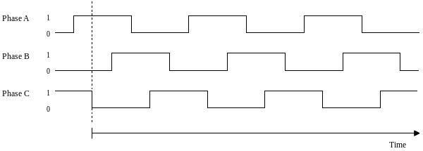
In addition to more stable operation, this approach leads to a duty cycle of each phase of 1/2, rather than 1/3 as in the simpler sequence.
Control
The control system is responsible for giving the required sequential pulses to the power circuitry. It is possible to do this using electro-mechanical means such as commutators or simple analog or digital timing circuits.
Many controllers incorporate programmable logic controllers (PLCs) rather than electromechanical components. A microcontroller can be used to enable precise timing of phase activations. It also enables a soft start function in software form, in order to reduce the amount of hardware required. A feedback loop enhances the control system.[1]
Power circuitry
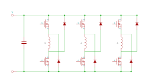
The most common approach to powering a switched reluctance motor is to use an asymmetric bridge converter. The switching frequency can be 10 times lower than for AC motors.[3]
The phases in an asymmetric bridge converter correspond to the phases of the switched reluctance motor. If both of the power switches on either side of the phase are turned on, then that corresponding phase shall be actuated. Once the current has risen above the set value, the switch turns off. The energy now stored within the motor winding maintains the current in the same direction until that energy is depleted.
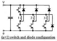
This basic circuitry may be altered so that fewer components are required although the circuit performs the same action. This efficient circuit is known as the (n+1) switch and diode configuration.
A capacitor, in either configuration, is used to suppress electrical and acoustic noise by limiting fluctuations in the supply voltage.
If a phase is disconnected, an SR motor may continue to operate at lower torque, unlike an AC induction motor which turns off.[5][10]
References
- Bartos, Frank (1 February 2003). "Springtime for Switched-Reluctance Motors?". Control Engineering. Archived from the original on 19 May 2020.
Digital signal processors and special algorithms in SR controls are vital to precisely time current pulses fed to the motor windings relative to rotor and stator position . SR technology has not experienced real breakthroughs . reduced interest in SR technology
- Stankovic, A.M. "Dept. of Electr. & Comput. Eng". doi:10.1109/IAS.1996.557001. Cite journal requires
|journal=(help) - Bartos, Frank (1 March 2010). "Resurgence for SR Motors, Drives?". Control Engineering. Archived from the original on 19 May 2020.
SR drives operate at switching frequencies typically 10 times lower than comparable ac drives . Some other sources seem to put both motors in the same category.) Emotron concurs that today’s SR motor is not a stepping motor since current is continuously monitored and controlled relative to rotor angular position
- "Switched Reluctance Generators and Their Control". Archived from the original on 2014-11-29. Retrieved 2016-11-18.CS1 maint: BOT: original-url status unknown (link)
- Bartos, Frank (10 March 2010). "SR motor anatomy: See inside switched reluctance motors". Control Engineering. Archived from the original on 2018-10-27.
- "Variable-speed switched reluctance motors", P.J. Lawrenson, J.M. Stephenson, P.T. Blenkinsop, J. Corda and N.N. Fulton, IEE Proceedings B - Electric Power Applications, Volume 127, Issue 4, 1980. pp. 253-265
- "IEEE Edison Medal Recipients". www.ieee.org. Archived from the original on 19 May 2020.
- Bartos, Frank (1 November 1999). "'Forward to the Past' with SR Technology". Control Engineering. Archived from the original on 19 May 2020.
- Bartos, Frank (30 May 2003). "Switched-Reluctance Motors and Controls Offer an Alternative Solution". Control Engineering. Archived from the original on 19 May 2020.
Because of their relatively smaller production numbers, manufacturing costs for SR technology tend to be higher
- "Fault tolerance in SR systems".
- Bush, Steve (2009). "Dyson vacuums 104,000 rpm brushless DC technology". Electronics Weekly Magazine. Archived from the original on 2012-04-11.
- "Tesla Model 3 Motor — Everything I've Been Able To Learn About It (Welcome To The Machine)". CleanTechnica. March 11, 2018. Retrieved 2018-06-18.
External links
| Wikimedia Commons has media related to Switched reluctance machines. |
- Switched Reluctance Motor Drives
- Real-Time Simulation and Control of Reluctance Motor Drives for High Speed Operation with Reduced Torque Ripple
- Torrey - Switched reluctance generators and their control DOI: 10.1109/41.982243
- Asadi - Development and application of an advanced switched reluctance generator drive
- SR database archive
- Adam Biernat: Electrical Machines in the Power Engineering and Automatics (Warsaw Polytechnic)
- Synchronous Reluctance Motor Intoduction Concepts