Combined cycle
| Thermodynamics | ||||||||||||
|---|---|---|---|---|---|---|---|---|---|---|---|---|
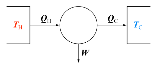 The classical Carnot heat engine | ||||||||||||
|
||||||||||||
| Book:Thermodynamics | ||||||||||||


In electric power generation a combined cycle is an assembly of heat engines that work in tandem from the same source of heat, converting it into mechanical energy, which in turn usually drives electrical generators. The principle is that after completing its cycle (in the first engine), the temperature of the working fluid engine is still high enough that a second subsequent heat engine may extract energy from the waste heat that the first engine produced. By combining these multiple streams of work upon a single mechanical shaft turning an electric generator, the overall net efficiency of the system may be increased by 50–60%. That is, from an overall efficiency of say 34% (in a single cycle) to possibly an overall efficiency of 62.22% (in a mechanical combination of two cycles) in net Carnot thermodynamic efficiency. This can be done because heat engines are only able to use a portion of the energy their fuel generates (usually less than 50%). In an ordinary (non combined cycle) heat engine the remaining heat (i.e., hot exhaust gas) from combustion is generally wasted.
Combining two or more thermodynamic cycles results in improved overall efficiency, reducing fuel costs. In stationary power plants, a widely used combination is a gas turbine (operating by the Brayton cycle) burning natural gas or synthesis gas from coal, whose hot exhaust powers a steam power plant (operating by the Rankine cycle). This is called a Combined Cycle Gas Turbine (CCGT) plant, and can achieve a best-of-class real (HHV - see below) thermal efficiency of around 62% in base-load operation, in contrast to a single cycle steam power plant which is limited to efficiencies of around 35–42%. Many new gas power plants in North America and Europe are of the Combined Cycle Gas Turbine type. Such an arrangement is also used for marine propulsion, and is called a combined gas and steam (COGAS) plant. Multiple stage turbine or steam cycles are also common.
Other historically successful combined cycles have used hot cycles with mercury vapour turbines, magnetohydrodynamic generators or molten carbonate fuel cells, with steam plants for the low temperature "bottoming" cycle. Bottoming cycles operating from a steam condenser's heat exhaust are theoretically possible, but uneconomical because of the very large, expensive equipment needed to extract energy from the small temperature differences between condensing steam and outside air or water. However, it is common in cold climates (such as Finland) to drive community heating systems from a power plant's condenser heat. Such cogeneration systems can yield theoretical efficiencies above 95%.
In automotive and aeronautical engines, turbines have been driven from the exhausts of Otto and Diesel cycles. These are called turbo-compound engines (not to be confused with turbochargers).
Basic combined cycle
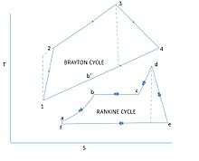
The thermodynamic cycle of the basic combined cycle consists of two power plant cycles. One is the Joule or Brayton cycle which is a gas turbine cycle and the other is Rankine cycle which is a steam turbine cycle.[1] The cycle 1-2-3-4-1 which is the gas turbine power plant cycle is the topping cycle. It depicts the heat and work transfer process taking place in high temperature region.
The cycle a-b-c-d-e-f-a which is the Rankine steam cycle takes place at a low temperature and is known as the bottoming cycle. Transfer of heat energy from high temperature exhaust gas to water and steam takes place by a waste heat recovery boiler in the bottoming cycle. During the constant pressure process 4-1 the exhaust gases in the gas turbine reject heat. The feed water, wet and super heated steam absorb some of this heat in the process a-b, b-c and c-d.
Steam generators

The steam power plant gets its input heat from the high temperature exhaust gases from gas turbine power plant.[1] The steam generated thus can be used to drive steam turbine. The Waste Heat Recovery Boiler (WHRB) has 3 sections: Economiser, evaporator and superheater.
Design principles
The efficiency of a heat engine, the fraction of input heat energy that can be converted to useful work, is limited by the temperature difference between the heat entering the engine and the exhaust heat leaving the engine.
In a thermal power station, water is the working medium. High pressure steam requires strong, bulky components. High temperatures require expensive alloys made from nickel or cobalt, rather than inexpensive steel. These alloys limit practical steam temperatures to 655 °C while the lower temperature of a steam plant is fixed by the temperature of the cooling water. With these limits, a steam plant has a fixed upper efficiency of 35–42%.
An open circuit gas turbine cycle has a compressor, a combustor and a turbine. For gas turbines the amount of metal that must withstand the high temperatures and pressures is small, and lower quantities of expensive materials can be used. In this type of cycle, the input temperature to the turbine (the firing temperature), is relatively high (900 to 1,400 °C). The output temperature of the flue gas is also high (450 to 650 °C). This is therefore high enough to provide heat for a second cycle which uses steam as the working fluid (a Rankine cycle).
In a combined cycle power plant, the heat of the gas turbine's exhaust is used to generate steam by passing it through a heat recovery steam generator (HRSG) with a live steam temperature between 420 and 580 °C. The condenser of the Rankine cycle is usually cooled by water from a lake, river, sea or cooling towers. This temperature can be as low as 15 °C.
Typical size of CCGT plants
Plant size is important in the cost of the plant. The larger plant sizes benefit from economies of scale (lower initial cost per kilowatt) and improved efficiency.
For large-scale power generation, a typical set would be a 270 MW primary gas turbine coupled to a 130 MW secondary steam turbine, giving a total output of 400 MW. A typical power station might consist of between 1 and 6 such sets.
Gas turbines for large-scale power generation are manufactured by at least four separate groups – General Electric, Siemens, Mitsubishi-Hitachi, and Ansaldo Energia. These groups are also developing, testing and/or marketing gas turbine sizes in excess of 300 MW (for 60 Hz applications) and 400 MW (for 50 Hz applications). Combined cycle units are made up of one or more such gas turbines, each with a waste heat steam generator arranged to supply steam to a single or multiple steam turbines, thus forming a combined cycle block or unit. Combined cycle block sizes offered by three major manufacturers (Alstom, General Electric and Siemens) can range anywhere from 50 MW to well over 1300 MW with costs approaching $670/kW.[2]
Unfired boiler
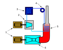
The heat recovery boiler is item 5 in the COGAS figure shown above. Hot gas turbine exhaust enters in super heater and the evaporator and then in to economiser section as it flows out from the boiler. Feed water comes in through the economizer and then exits after having attained saturation temp in the water or steam circuit. Finally it then flows through evaporator and super heater. If the temperature of the gases entering the heat recovery boiler is higher, then the temperature of the exiting gases is also high.[1]
Dual pressure boiler
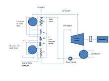
It is often desirable if high heat is recovered from the exiting gases. Hence dual pressure boiler is employed for this purpose.[1] It has two water/steam drums. Low pressure drum is connected to low pressure economizer or evaporator. The low pressure steam is generated in low temperature zone. The low pressure steam is supplied to the low temperature turbine. Super heater can be provided in the low pressure circuit.
Some part of the feed water from the low-pressure zone is transferred to the high-pressure economizer by a booster pump. This economizer heats up the water to its saturation temperature. This saturated water goes through the high-temperature zone of the boiler and is supplied to the high-pressure turbine.

Supplementary firing
Supplementary firing may be used in combined cycles (in the HRSG) raising exhaust temperatures from 600 °C (GT exhaust) to 800 or even 1000 °C. Using supplemental firing will however not raise the combined cycle efficiency for most combined cycles. For single boilers it may raise the efficiency if fired to 700–750 °C; for multiple boilers however, supplemental firing is often used to improve peak power production of the unit, or to enable higher steam production to compensate for failure of a second unit.
Maximum supplementary firing refers to the maximum fuel that can be fired with the oxygen available in the gas turbine exhaust. The steam cycle is conventional with reheat and regeneration. Hot gas turbine exhaust is used as the combustion air. Regenerative air preheater is not required. A fresh air fan which makes it possible to operate the steam plant even when the gas turbine is not in operation, increases the availability of the unit.
The use of large supplementary firing in Combined Cycle Systems with high gas turbine inlet temperatures causes the efficiency to drop. For this reason the Combined Cycle Plants with maximum supplementary firing are only of minimal importance today, in comparison to simple Combined Cycle installations. However, they have two advantages that is a) coal can be burned in the steam generator as the supplementary fuel, b) has very good part load efficiency.
The HRSG can be designed with supplementary firing of fuel after the gas turbine in order to increase the quantity or temperature of the steam generated. Without supplementary firing, the efficiency of the combined cycle power plant is higher, but supplementary firing lets the plant respond to fluctuations of electrical load. Supplementary burners are also called duct burners.
More fuel is sometimes added to the turbine's exhaust. This is possible because the turbine exhaust gas (flue gas) still contains some oxygen. Temperature limits at the gas turbine inlet force the turbine to use excess air, above the optimal stoichiometric ratio to burn the fuel. Often in gas turbine designs part of the compressed air flow bypasses the burner and is used to cool the turbine blades.
Supplementary firing raises the temperature of the exhaust gas from 800 to 900 degree Celsius. Relatively high flue gas temperature raises the condition of steam (84 bar, 525 degree Celsius) thereby improving the efficiency of steam cycle.
Fuel for combined cycle power plants
Combined cycle plants are usually powered by natural gas, although fuel oil, synthesis gas or other fuels can be used. The supplementary fuel may be natural gas, fuel oil, or coal. Biofuels can also be used. Integrated solar combined cycle power stations combine the energy harvested from solar radiation with another fuel to cut fuel costs and environmental impact (look ISCC section). Next generation nuclear power plants are also on the drawing board which will take advantage of the higher temperature range made available by the Brayton top cycle, as well as the increase in thermal efficiency offered by a Rankine bottoming cycle.
The improvement in shale gas extraction has increased natural gas supplies and reserves dramatically.[3] Because of this fact, it is becoming the fuel of choice for an increasing amount of private investors and consumers because it is more versatile than coal or oil and can be used in 90% of energy applications. Chile which once depended on hydro-power for 70% of its electricity supply, is now boosting its gas supplies to reduce reliance on its drought afflicted hydro dams. Similarly China is tapping its gas reserves to reduce reliance on coal, which is currently burned to generate 80% of the country’s electricity supply.
Where the extension of a gas pipeline is impractical or cannot be economically justified, electricity needs in remote areas can be met with small-scale Combined Cycle Plants, using renewable fuels. Instead of natural gas, Combined Cycle Plants can be filled with biogas derived from agricultural and forestry waste, which is often readily available in rural areas.
Low-grade fuel for turbines
Gas turbines burn mainly natural gas and light oil. Crude oil, residual, and some distillates contain corrosive components and as such require fuel treatment equipment. In addition, ash deposits from these fuels result in gas turbine deratings of up to 15%. They may still be economically attractive fuels however, particularly in combined-cycle plants.
Sodium and potassium are removed from residual, crude and heavy distillates by a water washing procedure. A simpler and less expensive purification system will do the same job for light crude and light distillates. A magnesium additive system may also be needed to reduce the corrosive effects if vanadium is present. Fuels requiring such treatment must have a separate fuel-treatment plant and a system of accurate fuel monitoring to assure reliable, low-maintenance operation of gas turbines.
Configuration
A single shaft combined cycle plant comprises a gas turbine and a steam turbine driving a common generator. In a multi-shaft combined cycle plant, each gas turbine and each steam turbine has its own generator. The single shaft design provides slightly less initial cost and slightly better efficiency than if the gas and steam turbines had their own generators. The multi-shaft design enables two or more gas turbines to operate in conjunction with a single steam turbine, which can be more economical than a number of single shaft units.
The primary disadvantage of single shaft combined cycle power plants is that the number of steam turbines, condensers and condensate systems – and perhaps the number of cooling towers and circulating water systems – increases to match the number of gas turbines. For a multi-shaft combined cycle power plant there is only one steam turbine, condenser and the rest of the heat sink for up to three gas turbines; only their size increases. Having only one large steam turbine and heat sink results in low cost because of economies of scale. A larger steam turbine also allows the use of higher pressures and results in a more efficient steam cycle. Thus the overall plant size and the associated number of gas turbines required have a major impact on whether a single shaft combined cycle power plant or a multiple shaft combined cycle power plant is more economical.
The combined-cycle system includes single-shaft and multi-shaft configurations. The single-shaft system consists of one gas turbine, one steam turbine, one generator and one Heat Recovery Steam Generator (HRSG), with the gas turbine and steam turbine coupled to the single generator in a tandem arrangement on a single shaft. Key advantages of the single-shaft arrangement are operating simplicity, smaller footprint, and lower startup cost. Single-shaft arrangements, however, will tend to have less flexibility and equivalent reliability than multi-shaft blocks. Additional operational flexibility is provided with a steam turbine which can be disconnected, using a synchro-self-shifting (SSS) Clutch,[4] for start up or for simple cycle operation of the gas turbine.
Multi-shaft systems have one or more gas turbine-generators and HRSGs that supply steam through a common header to a separate single steam turbine-generator. In terms of overall investment a multi-shaft system is about 5% higher in costs.
Single- and multiple-pressure non-reheat steam cycles are applied to combined-cycle systems equipped with gas turbines having rating point exhaust gas temperatures of approximately 540 °C or less. Selection of a single- or multiple-pressure steam cycle for a specific application is determined by economic evaluation which considers plant installed cost, fuel cost and quality, plant duty cycle, and operating and maintenance cost.
Multiple-pressure reheat steam cycles are applied to combined-cycle systems with gas turbines having rating point exhaust gas temperatures of approximately 600 °C.
The most efficient power generation cycles are those with unfired HRSGs with modular pre-engineered components. These unfired steam cycles are also the lowest in cost. Supplementary-fired combined-cycle systems are provided for specific application.
The primary regions of interest for cogeneration combined-cycle systems are those with unfired and supplementary fired steam cycles. These systems provide a wide range of thermal energy to electric power ratio and represent the range of thermal energy capability and power generation covered by the product line for thermal energy and power systems.
Efficiency of CCGT plants
By combining both gas and steam cycles, high input temperatures and low output temperatures can be achieved. The efficiency of the cycles add, because they are powered by the same fuel source. So, a combined cycle plant has a thermodynamic cycle that operates between the gas-turbine's high firing temperature and the waste heat temperature from the condensers of the steam cycle. This large range means that the Carnot efficiency of the cycle is high. The actual efficiency, while lower than the Carnot efficiency, is still higher than that of either plant on its own.[5][6]
The electric efficiency of a combined cycle power station, if calculated as electric energy produced as a percentage of the lower heating value of the fuel consumed, can be over 60% when operating new, i.e. unaged, and at continuous output which are ideal conditions. As with single cycle thermal units, combined cycle units may also deliver low temperature heat energy for industrial processes, district heating and other uses. This is called cogeneration and such power plants are often referred to as a combined heat and power (CHP) plant.
In general, combined cycle efficiencies in service are over 50% on a lower heating value and Gross Output basis. Most combined cycle units, especially the larger units, have peak, steady-state efficiencies on the LHV basis of 55 to 59%. Research aimed at 1,370 °C (2,500 °F) turbine inlet temperature has led to even more efficient combined cycles and nearly 60% LHV efficiency (54% HHV efficiency) has been reached in the combined cycle unit of Baglan Bay, a GE H-technology gas turbine with a NEM 3 pressure reheat boiler, using steam from the HRSG to cool the turbine blades.
In May 2011 Siemens AG announced they had achieved a 60.75% net efficiency with a 578 megawatts SGT5-8000H gas turbine at the Irsching Power Station.[7] The General Electric 9HA was billed to attain 41.5% simple cycle efficiency and 61.4% in combined cycle mode, with a gas turbine output of 397 MW to 470 MW and a combined output of 592 MW to 701 MW. Its firing temperature is between 2,600 and 2,900 °F (1,430 and 1,590 °C), its overall pressure ratio is 21.8 to 1 and is used by Électricité de France in Bouchain. On April 28, 2016, this plant was certified by Guinness World Records as the worlds most efficient combined cycle power plant at 62.22%.[8] The Chubu Electric’s Nishi-ku, Nagoya power plant 405 MW 7HA is expected to have 62% gross combined cycle efficiency.[9] For 2018, GE offers its 826 MW HA at over 64% efficiency in combined cycle due to advances in additive manufacturing and combustion breakthroughs, up from 63.7% in 2017 orders and on track to achieve 65% by the early 2020s.[10]
As of January 2017, Mitsubishi claims a LHV efficiency of greater than 63% for some members of its J Series turbines.[11]
Difference between HHV and LHV
To avoid confusion, the efficiency of heat engines and power stations should be stated relative to the Higher Heating Value (HHV) or Lower Heating Value (LHV) of the fuel, to include or exclude the heat that can be obtained from condensing the flue gas. It should also be specified whether Gross output at the generator terminals or Net Output at the power station fence is being considered.
The LHV figure is NOT a computation of electricity net energy compared to energy content of fuel input; it is 11% higher than that. The HHV figure is a computation of electricity net energy compared to energy content of fuel input. If the LHV approach were used for some new condensing boilers, the efficiency would calculate to be over 100%. Manufacturers prefer to cite the higher LHV efficiency, e.g. 60%, for a new CCGT, but utilities, when calculated how much electricity the plant will generate, divide this by 1.11 to get the real, e.g. 54%, HHV efficiency of that CCGT. Coal plant efficiencies are computed on a HHV basis (it doesn't make nearly as much difference for coal burn, as for gas).
The difference between HHV and LHV for gas, can be estimated (using USA units) by 1055Btu/Lb * w, where w is the lbs of water after combustion per lb of fuel. To convert the HHV of natural gas, which is 23875 Btu/lb, to an LHV (methane is 25% hydrogen) would be: 23875 – (1055*0.25*18/2) = 21500. Because the efficiency is determined by dividing the energy output by the input, and the input on an LHV basis is smaller than the HHV basis, the overall efficiency on an LHV basis is higher. So, using the ratio: 23875/21500 = 1.11 you can convert the HHV to an LHV.
So a real best-of-class baseload CCGT efficiency of 54%, as experienced by the utility operating the plant, translates to 60% LHV as the manufacturer’s published headline CCGT efficiency.
Boosting efficiency
The efficiency of CCGT and GT can be boosted by pre-cooling combustion air. This is practised in hot climates and also has the effect of increasing power output. This is achieved by evaporative cooling of water using a moist matrix placed in front of the turbine, or by using Ice storage air conditioning. The latter has the advantage of greater improvements due to the lower temperatures available. Furthermore, ice storage can be used as a means of load control or load shifting since ice can be made during periods of low power demand and, potentially in the future the anticipated high availability of other resources such as renewables during certain periods.
Natural gas integrated power and syngas (hydrogen) generation cycle
A natural gas integrated power and syngas (hydrogen) generation cycle uses semi-closed (sometimes called closed) gas turbine cycles [12][13][14] where fuel is combusted with pure oxygen, and the working fluid of the cycle is a mix of combustion products CO2 (carbon dioxide) and H2O (steam).
The integrated cycle implies that, before combustion, methane (primer natural gas component) is mixed with working fluid and converted into syngas (mix of H2 and CO (carbon monoxide)) in a catalytic adiabatic (without an indirect heat supply) reactor by using sensible heat of the hot working fluid leaving, in the simplest case, the gas turbine outlet. The largest part of produced syngas (about 75%) is directed into the combustion chamber of the gas-turbine cycle to generate power, but another part of syngas (about 25%) is withdrawn from the power generation cycle as hydrogen, carbon monoxide, or their blend to produce chemicals, fertilizers, synthetic fuels, and etc.[15][16][17] The thermodynamic benefit owing to this modification is substantiated by exergy analysis. There are numerous technological options to separate syngas from working fluid and withdraw it from the cycle (e.g., condensing vapors and removing liquids, taking out gases and vapors by membrane and pressure swing adsorption separation, amine gas treating, and glycol dehydration).
All the environmental advantages of semi-closed gas turbine cycles as to an absence of NOx and the release of non-diluted CO2 in the flue gas stay the same. An effect of integration becomes apparent with the following clarification. Assigning the efficiency of syngas production in the integrated cycle a value equal to a regular syngas production efficiency through steam-methane reforming (some part of methane is combusted to drive endothermic reforming), the net-power generation efficiency (with accounting for the consumed electricity required to separate air) can reach levels higher than 60% [17] at a maximum temperature in the cycle (at the gas turbine inlet) of about 1300oC.
The natural gas integrated cycle with adiabatic catalytic reactor was firstly proposed at Chemistry Department of Moscow State Lomonosov University (Russia) in Prof. M. Safonov (late) group by M. Safonov,M. Granovskii, and S. Pozharskii in 1993.[15]
Integrated gasification combined cycle (IGCC)
An integrated gasification combined cycle, or IGCC, is a power plant using synthesis gas (syngas). Syngas can be produced from a number of sources, including coal and biomass. The system uses gas and steam turbines, the steam turbine operating off of the heat left over from the gas turbine. This process can raise electricity generation efficiency to around 50%.
Integrated solar combined cycle (ISCC)
An Integrated Solar Combined Cycle (ISCC) is a hybrid technology in which a solar thermal field is integrated within a combined cycle plant. In ISCC plants, solar energy is used as an auxiliary heat supply, supporting the steam cycle, which results in increased generation capacity or a reduction of fossil fuel use.[18]
Thermodynamic benefits are that daily steam turbine startup losses are eliminated.[19]
Major factors limiting the load output of a combined cycle power plant are the allowed pressure and temperature transients of the steam turbine and the heat recovery steam generator waiting times to establish required steam chemistry conditions and warm-up times for the balance of plant and the main piping system. Those limitations also influence the fast start-up capability of the gas turbine by requiring waiting times. And waiting gas turbines consume gas. The solar component, if the plant is started after sunshine, or before, if we have heat storage, allows us to preheat the steam to the required conditions. That is, the plant is started faster and we consume less gas before achieving operating conditions.[20] Economic benefits are that the solar components costs are 25% to 75% those of a Solar Energy Generating Systems plant of the same collector surface.[21]
The first such system to come online was the Archimede combined cycle power plant, Italy in 2010,[22] followed by Martin Next Generation Solar Energy Center in Florida, and in 2011 by the Kuraymat ISCC Power Plant in Egypt, Yazd power plant in Iran,[23][24] Hassi R'mel in Algeria, Ain Beni Mathar in Morocco.
Automotive use
Combined cycles have traditionally only been used in large power plants. BMW, however, has proposed that automobiles use exhaust heat to drive steam turbines.[25] This can even be connected to the car or truck's cooling system to save space and weight, but also to provide a condenser in the same location as the radiator and preheating of the water using heat from the engine block.
It may be possible to use the pistons in a reciprocating engine for both combustion and steam expansion as in the Crower engine.[26]
A turbocharged car is also a combined cycle. Bowman of Southampton offer a commercially proven add-on turbocharger which additionally can generate electric power lowering overall fuel consumption by about 8%.
Aeromotive use
Some versions of the Wright R-3350 were produced as turbo-compound engines. Three turbines driven by exhaust gases, known as power recovery turbines (unofficially "parts recovery turbines" because they ate exhaust valves on a regular basis) provided nearly 600 hp at takeoff. These turbines added power to the engine crankshaft through bevel gears and fluid couplings.[27]
There have been many successful turbo-compound engine designs particularly for aircraft but their mechanical complexity and weight are less economical than multistage turbine engines. Stirling engines are also a good theoretical fit for this application.
See also
References
- 1 2 3 4 Yahya, S.M. Turbines, compressors and fans. Tata Mc Graw Hill. pp. chapter 5.
- ↑ "Combined-cycle, gas-fired unit costs coming in below expectations: Duke | S&P Global Platts". 2015-08-11.
- ↑ "Natural Gas reserves". BP. Archived from the original on 25 April 2012. Retrieved 19 September 2011.
- ↑ "SSS Clutch Operating Principle" (PDF). SSS Gears Limited.
- ↑ "Efficiency by the Numbers" by Lee S. Langston
- ↑ "The difference between LCV and HCV (or Lower and Higher Heating Value, or Net and Gross) is clearly understood by all energy engineers. There is no 'right' or 'wrong' definition". Claverton Energy Research Group.
- ↑ "Siemens pushes world record in efficiency to over 60% while achieving maximum operating flexibility". Siemens AG. 19 May 2011.
- ↑ "Most efficient combined cycle power plant".
- ↑ "Air-cooled 7HA and 9HA designs rated at over 61% CC efficiency". Gas Turbine World. April 2014.
- ↑ "HA technology now available at industry-first 64 percent efficiency" (Press release). GE Power. December 4, 2017.
- ↑ Record-Breaking Efficiency
- ↑ Allam, Rodney; Martin, Scott; Forrest, Brock; Fetvedt, Jeremy; Lu, Xijia; Freed, David; Brown, G. William; Sasaki, Takashi; Itoh, Masao; Manning, James (2017). "Demonstration of the Allam Cycle: An Update on the Development Status of a High Efficiency Supercritical Carbon Dioxide Power Process Employing Full Carbon Capture". Energy Procedia. 114: 5948–5966. doi:10.1016/j.egypro.2017.03.1731.
- ↑ F.Viteri, R.Anderson. (2013). "Semi-closed Brayton cycle gas turbine power systems". United States Patent, No.:US 6,622,470, Sep.23,2003.
- ↑ P.Pak, K.Nakamura, Y.Suzuki. (1993). "Power generation plant and power generation method without emission of carbon dioxide". United States Patent, No.:US 5,175,995, Jan.5,1993.
- 1 2 M.Safonov, M.Granovskii, S.Pozharskii (1993). "Thermodynamic efficiency of co-generation of energy and hydrogen in gas-turbine cycle of methane oxidation". Doklady Akademii Nauk (Rossii), 328(1993) 202-204.
- ↑ M.Granovskii, M.Safonov, S.Pozharskii (2002). "Integrated Scheme of Natural Gas Usage with Minimum Production of Entropy". Canadian Journal of Chemical Engineering, 80(2002)998-1001.
- 1 2 M.Granovskii, M.Safonov (2003). "New Integrated Scheme of the Closed Gas-Turbine Cycle with Synthesis Gas Production". Chemical Engineering Science, 58(2003)3913-3921.
- ↑ Integrated solar combined cycle plants Archived 2013-09-28 at the Wayback Machine.
- ↑ "Fossil Fuels + Solar Energy = The Future of Electricity Generation". POWER magazine. 2009-01-04. p. 1 (paragraph 7). Retrieved 2017-12-25.
- ↑ Operational Flexibility Enhancements of Combined Cycle Power Plants p.3
- ↑ Integrated Solar Combined Cycle Systems Archived 2013-09-25 at the Wayback Machine.
- ↑ "ENEL a Priolo inaugura la centrale "Archimede"". ENEL. 14 July 2010. Archived from the original on 25 May 2015.
- ↑ "Yazd Solar Energy Power Plant 1st in its kind in world". Payvand Iran news. 13 April 2007.
- ↑ "Iran - Yazd integrated solar combined cycle power station". Helios CSP. 21 May 2011. Archived from the original on 12 August 2014.
- ↑ "BMW Turbosteamer gets hot and goes" by John Neff, AutoBlog, December 9, 2005
- ↑ "Inside Bruce Crower’s Six-Stroke Engine" By Pete Lyons, AutoWeek, February 23, 2006
- ↑ "Goleta Air and Space Museum: 2002 Camarillo EAA Fly-in".
Further reading
- Steam & Gas Turbines And Power Plant Engineering ISBN C039000000001, R Yadav., Sanjay., Rajay, Central Publishing House, Allahabad
- Applied Thermodynamics ISBN 9788185444031, R Yadav., Sanjay., Rajay, Central Publishing House, Allahabad.
- Thermodynamic Evaluation of Advanced Combined Cycle Using Latest Gas Turbine http://proceedings.asmedigitalcollection.asme.org/proceeding.aspx?articleid=1570593
- Sanjay, Y; Singh, Onkar; Prasad, BN (December 2007). "Energy and exergy analysis of steam cooled reheat gas-steam combined cycle". Applied Thermal Engineering. 27 (17–18): 2779–2790. doi:10.1016/j.applthermaleng.2007.03.011.
External links
| Wikimedia Commons has media related to Combined cycle power generators. |