T-antenna
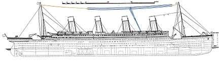
A T-antenna, T-aerial, flat-top antenna, or top-hat antenna is a capacitively loaded monopole wire radio antenna[1] used in the VLF, LF, MF and shortwave bands.[2][3][4] T-antennas are widely used as transmitting antennas for amateur radio stations,[5] long wave and medium wave broadcasting stations. They are also used as receiving antennas for shortwave listening.
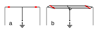
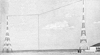
The antenna consists of one or more horizontal wires suspended between two supporting radio masts or buildings and insulated from them at the ends.[1][4] A vertical wire is connected to the center of the horizontal wires and hangs down close to the ground, connected to the transmitter or receiver. Combined, the two sections form a "T" shape, hence the name. The transmitter power is applied, or the receiver is connected, between the bottom of the vertical wire and a ground connection.
The T-antenna functions as a monopole antenna with capacitive top-loading; other antennas in this category include the inverted-L, umbrella, and triatic antennas. It was invented during the first decades of radio, in the wireless telegraphy era, before 1920.
How it works
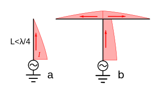
When the length of the wire segments are shorter than a quarter wavelength (λ/4) of the radio waves, as is typical for use below 1 MHz, the antenna functions as a vertical electrically short monopole antenna with capacitive top-loading.[3] Because the two horizontal arms of the "T" have equal but oppositely-directed currents in them, which causes the radio waves from them to cancel far from the antenna, and because of similar cancelling ground currents, the horizontal wire radiates little radio power.[7] Instead it serves to add capacitance to the top of the antenna.[6][7] This increases the currents in the upper portion of the vertical wire (see drawing at right), increasing the radiation resistance and thus its efficiency,[6] allowing it to radiate more power, or in a receiving antenna be more sensitive to incoming radio signals. The top load wire can increase radiated power by 2 to 4 times (3 to 6 dB) for a given base current.[6]
However, the antenna is still typically not as efficient as a full-height λ/4 vertical monopole,[5] and has a higher Q and thus a narrower bandwidth. T-antennas are typically used at low frequencies where it is not practical to build a quarter-wave vertical antenna because of its height,[4][8] and the vertical radiating wire is often very electrically short: only a small fraction of a wavelength long, 0.1 λ or less. An electrically short antenna has a base reactance that is capacitive, and in transmitting antennas this must be tuned-out by an added loading coil to make the antenna resonant so it can be fed power efficiently.
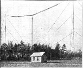
To increase the top-load capacitance, several parallel horizontal wires are often used, connected together at the center where the vertical wire attaches.[5] The capacitance does not increase proportionally with the number of wires, however, because each wire’s electric field is partially shielded from the ground by its adjacent wires.[5]
Radiation pattern
Since the vertical wire is the actual radiating element, the antenna radiates vertically polarized radio waves in an omnidirectional radiation pattern, with equal power in all azimuthal directions.[9] The axis of the horizontal wire makes little difference. The power is maximum in a horizontal direction or at a shallow elevation angle, decreasing to zero at the zenith. This makes it a good antenna at LF or MF frequencies, which propagate as ground waves with vertical polarization, but it also radiates enough power at higher elevation angles to be useful for sky wave ("skip") communication. The effect of poor ground conductivity is generally to tilt the pattern up, with the maximum signal strength at a higher elevation angle.
Transmitting antennas
If it is shorter than λ/4 any monopole antenna has a capacitive reactance; the shorter it is, the higher the reactance. The horizontal top section of a T-antenna reduces the capacitive reactance, substituting for a vertical section whose height would be about 2⁄3 its length[10]; if it is long enough, it completely eliminates reactance. In transmitting antennas, to make the antenna resonant so it can be driven efficiently the capacitance must be canceled out by inserting a loading coil the antenna, if the top-section is not long enough to do so. Usually the loading coil is at the base of the antenna, connected between the antenna and its feedline.
At medium and low frequencies, the high antenna capacitance and the high inductance of the loading coil compared to its low radiation resistance makes the loaded antenna behave like a high Q tuned circuit, with a narrow bandwidth over which it will remain well matched to the transmission line, when compared to a λ/4 monopole.
To operate over a large frequency range the loading coil often must be adjustable, and adjusted when the frequency is changed to keep the SWR low. The high Q also causes a high voltage on the antenna, which is maximum at the current nodes at the ends of the horizontal wire, roughly Q times the driving-point voltage. The insulators at the ends must be designed to withstand these voltages. In high power transmitters the output power is often limited by the onset of corona discharge on the wires.[11]
Radiation resistance is the equivalent resistance of an antenna due to its radiation of radio waves; for a full-length quarter-wave monopole the radiation resistance is around 25 ohms. An antenna short compared to a wavelength has a lower radiation resistance; thus at low frequencies the T-antenna can have very low radiation resistance, often less than 1 ohm,[5][12] so the efficiency is limited by other resistances in the antenna and the ground system. The input power is divided between the radiation resistance and the "ohmic" resistances of the antenna-ground circuit, chiefly the coil and the ground. The resistance in the coil and particularly the ground system must be kept very low to minimize the power dissipated in them.
It can be seen that at low frequencies the design of the loading coil can be challenging:[5] it must have high inductance but very low losses at the transmitting frequency (high Q), must carry high currents, withstand high voltages at its ungrounded end, and be adjustable.[8] It is often made of litz wire.[8]
At low frequencies the antenna requires a good low resistance ground to be efficient. The RF ground is typically constructed of a "star" of many radial copper cables buried about 1 ft. in the earth, extending out from the base of the vertical wire, and connected together at the center. The radials should ideally be long enough to extend beyond the displacement current region near the antenna. At VLF frequencies the resistance of the soil becomes a problem, and the radial ground system is usually raised and mounted a few feet above ground, insulated from it, to form a counterpoise.
Equivalent circuit
The power radiated (or received) by an electrically short vertical antenna like the T-antenna is proportional to the square of the "effective height" of the antenna,[5] so the antenna should be made as high as possible. Without the horizontal wire, the RF current distribution in the vertical wire would decrease linearly to zero at the top (see drawing a above), giving an effective height of half the physical height of the antenna. With an ideal "infinite capacitance" top load wire, the current in the vertical would be constant along its length, giving an effective height equal to the physical height, therefore increasing the power radiated fourfold. So the power radiated (or received) by a T antenna is up to four times that of a vertical monopole of the same height.
The radiation resistance of an ideal T antenna with very large top load capacitance is[6]

so the radiated power is

where h is the height of the antenna, λ is the wavelength, and I0 is the RMS input current in amperes. This formula shows that the radiated power depends on the product of the base current and the effective height, and is used to determine how many 'metre-amps' are required for a given amount of radiated power.
The equivalent circuit of the antenna (including loading coil) is the series combination of the capacitive reactance of the antenna, the inductive reactance of the loading coil, and the radiation resistance and the other resistances of the antenna-ground circuit. So the input impedance is

At resonance the capacitive reactance of the antenna is cancelled by the loading coil so the input impedance at resonance z0 is just the sum of the resistances in the antenna circuit[13]

So the efficiency η of the antenna, the ratio of radiated power to input power from the feedline, is

where
- RC is the ohmic resistance of the antenna conductors (copper losses)
- RD is the equivalent series dielectric losses
- RL is the equivalent series resistance of the loading coil
- RG is the resistance of the ground system
- RR is the radiation resistance
- C is the capacitance of the antenna at the input terminals
- L is the inductance of the loading coil
It can be seen that, since the radiation resistance is usually very low, the major design problem is to keep the other resistances in the antenna-ground system low to obtain the highest efficiency.[13]
Multiple-tuned antenna
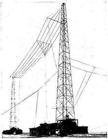
The "multiple-tuned flattop antenna" is a variant of the T antenna used in high power low frequency transmitters to reduce ground power losses.[8] It consists of a long capacitive top-load consisting of multiple parallel wires supported by a line of transmission towers, sometimes several miles long. Several vertical radiator wires hang down from the top-load, each attached to its own ground through a loading coil. The antenna is driven either at one of the radiator wires, or more often at one end of the top-load, by bringing the wires of the top-load diagonally down to the transmitter. Although the vertical wires are separated, the distance between them is small compared to the length of the LF waves, so the currents in them are in phase and they can be considered as one radiator. Since the antenna current flows into the ground through N parallel loading coils and grounds rather than one, the equivalent loading coil and ground resistance, and therefore the power dissipated in the loading coil and ground, is reduced to 1/N that of a simple T antenna.[8] The antenna was used in the powerful radio stations of the wireless telegraphy era but has fallen out of favor due to the expense of multiple loading coils.
See also
References
- 1 2 Graf, Rudolf F. (1999). Modern dictionary of electronics, 7th Ed. USA: Newnes. p. 761. ISBN 0-7506-9866-7.
- ↑ Chatterjee, Rajeswari (2006). Antenna theory and practice, 2nd Ed. New Delhi: New Age International. pp. 243–244. ISBN 81-224-0881-8.
- 1 2 Rudge, Alan W. (1983). The Handbook of Antenna Design, Vol. 2. IET. pp. 578–579. ISBN 0-906048-87-7.
- 1 2 3 Edwards, R.J.Edwards G4FGQ (August 1, 2005). "The Simple Tee Antenna". Antenna design library. S meter website. Retrieved 2012-02-23. External link in
|publisher=(help) - 1 2 3 4 5 6 7 Straw, R. Dean, Ed. (2000). The ARRL Antenna Book, 19th Ed. USA: American Radio Relay League. p. 6.36. ISBN 0-87259-817-9.
- 1 2 3 4 5 Huang, Yi; Kevin Boyle (2008). Antennas: from theory to practice. John Wiley & Sons. pp. 299–301. ISBN 0-470-51028-5.
- 1 2 Rudge, 1983, p.554
- 1 2 3 4 5 Griffith, B. Whitfield (2000). Radio-Electronic Transmission Fundamentals, 2nd Ed. USA: SciTech Publishing. pp. 389–391. ISBN 1-884932-13-4.
- ↑ Barclay, Leslie W. (2000). Propagation of radiowaves. Institution of Electrical Engineers. pp. 379–380. ISBN 0-85296-102-2.
- ↑ Moxon, Les (1994). "12 HF Antennas". In Biddulph, Dick. Radio Communication Handbook (6th ed.). Radio Society of Great Britain.
- ↑ LaPorte, Edmund A. (2010). "Antenna Reactance". Radio Antenna Engineering. Virtual Institute of Applied Science. Retrieved 2012-02-24. External link in
|publisher=(help) - ↑ Balanis, Constantine A. (2011). Modern Antenna Handbook. John Wiley & Sons. pp. 2.8–2.9 (Sec. 2.2.2). ISBN 1-118-20975-3.
- 1 2 LaPorte, Edmund A. (2010). "Radiation Efficiency". Radio Antenna Engineering. Virtual Institute of Applied Science. Retrieved 2012-02-24. External link in
|publisher=(help)