Umbrella antenna
An umbrella antenna is a top-loaded electrically lengthened monopole antenna, consisting in most cases of a mast fed at the ground end, to which a number of radial wires are connected at the top, sloping downwards. They are used as transmitting antennas below 1 MHz, in the LF and particularly the VLF bands, at frequencies sufficiently low that it is impractical or infeasible to build a full size quarter-wave monopole antenna.

The outer end of each radial wire, sloping down from the top of the antenna, is connected by an insulator to a supporting rope or (usually) insulated cable anchored to the ground; the radial wires can also support the mast as guy wires. The radial wires make the antenna look like the frame of a giant umbrella – without the cloth – hence the name.
History
Umbrella antennas were invented during the wireless telegraphy era, about 1900 to 1920, and used with spark-gap transmitters on longwave bands to transmit information by Morse code. Small umbrella antennas were widely used with portable transmitters by military signal corps during World War I, since there was no possibility of setting up full-sized quarter-wave antennas.
Umbrella antennas were used at most OMEGA Navigation System transmitters, operating around 10 kHz, and at LORAN-C stations, operating at 100 kHz with central masts approximately 200 metres tall, before those systems were shut down.
Structure
Either the central mast itself, or a “cage” of vertical wires parallel to the mast, is connected to the transmitter and serves as the radiating element. At the low frequencies used the height of the mast is typically a small fraction of a wavelength, so it makes a very electrically short antenna, and by itself would have very low radiation resistance and would be a very inefficient radiator. The umbrella-wires add capacitance to the top of the antenna, improving the current distribution on the vertical mast radiator and increasing the radiation resistance and hence the radiated power. The umbrella wires serve as the plate of a capacitor, with the ground serving as the other plate, which is charged and discharged by the radio frequency current from the transmitter.
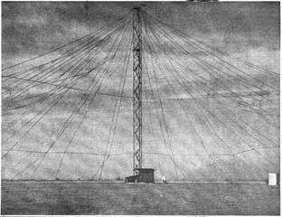 Umbrella antenna for early VLF spark transmitter at Nauen Transmitter Station, Nauen, Germany, 1907.
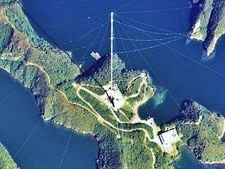 Antenna H of the Omega navigation system, an obsolete radio navigation system, Tsushima, Japan, 389 meters, built 1973. Transmitted on 10 - 14 kHz.
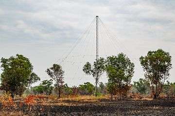 Antenna of Radio Televisyen Malaysia (RTM), Tuaran, Sabah district, Malaysia
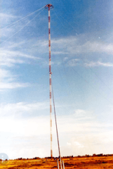 428 meter Chabrier Omega Transmitter (station E ) antenna near Chabrier on Réunion island.
Umbrella antennas radiate vertically polarised ground waves in an omnidirectional radiation pattern. Because they are short compared to a wavelength of the radio waves, they have low radiation resistance and are usually inefficient, radiating only a fraction of the power supplied by the transmitter.
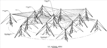
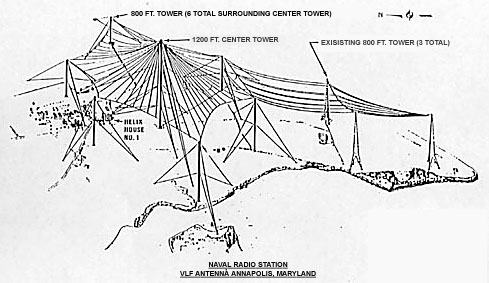
Umbrella antennas can be built as single mast antennas or as multiple mast antennas. In single mast antennas, the radial wires connected to the top of the antenna mast are anchored to the ground, and they and the mast are (usually) insulated from the ground. In multiple mast antennas the radial wires connect between the top of the central mast and the tops of outer masts, arranged in a circle around the central mast; the outer masts are usually smaller than the central mast and are often grounded.
It is also possible to build an umbrella antenna which is fed at the ends of the radial wires. The central mast is grounded. This requires separate feedlines to each umbrella wire.
To tune out the large capacitive reactance of the antenna and make it resonant at the operating frequency so it can be fed power efficiently, a large inductor (loading coil) is placed in series with the feedline at the base of the antenna. The other side of the feedline from the transmitter is connected to a ground under the antenna. Because of the very small radiation resistance of the antenna, in order to avoid losing excessive power to resistive losses the ground system must have extremely low resistance. The ground system consists of a radial network of many cables buried a few feet in the ground radiating from the central mast of the antenna out beyond the umbrella wires. At VLF frequencies a buried ground has unacceptably high losses, and a counterpoise is usually used, consisting of a radial screen of wires suspended a short distance above the ground under the antenna.
Present use
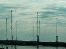
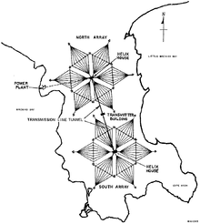
Due to their large capacitive topload, umbrella antennas are some of the most efficient antenna designs at low frequencies, and are used for transmitters in the LF and VLF bands for navigational aids and military communication. The largest umbrella antennas have been built for VLF naval transmitting stations which communicate with submerged submarines. They are also in common use for commercial medium-wave and longwave AM broadcasting stations. Umbrella antennas with heights of 15–460 metres are in service. The tallest umbrella antennas are actually used by Lualualei VLF transmitter, INS Kattabomman and the CHAYKA-transmitters at Inta and Dudinka. Eight umbrella antennas 350 metres high are in use in an array at the German VLF communications facility, operating at about 20 kHz with high radiation efficiency even though they are less than 1⁄40 wavelength high.
With the progressing world-wide adoption of two new amateur radio bands at 630 metres and 2200 metres, amateurs with adequate real estate have resumed use of this design.