Rhombic antenna
A rhombic antenna is a broadband directional wire antenna co-invented by Edmond Bruce[1] and Harald Friis,[2][3] in 1931, mostly commonly used in the high frequency (HF) or shortwave band.
Description
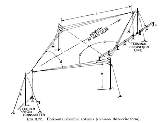
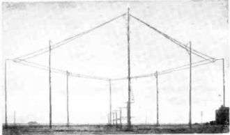
A rhombic antenna consists of one to three parallel wires suspended above the ground in a "rhombic" (diamond) shape, supported by poles or towers at each vertex to which the wires are attached by insulators. Each of the four sides are the same length. The length is not critical, typically from one to two wavelengths (λ). A horizontal rhombic antenna (picture, top right) radiates horizontally polarized radio waves at a low elevation angle off the end of the antenna opposite the feedline. Its principal advantages over other types of antenna are its simplicity, high forward gain and wide bandwidth, the ability to operate over a wide range of frequencies.
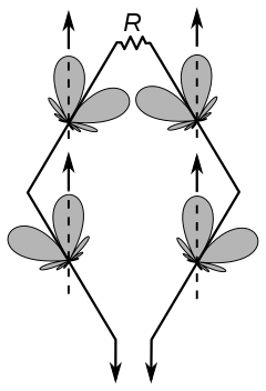
It is typically fed at one of the two acute (sharper angle) vertices through a balanced transmission line, or alternatively a coaxial cable with a balun transformer. The end of the wires meeting at the opposite vertex is either left open (unconnected), or terminated with a non-inductive resistor. When resistor-terminated, the radiation pattern is unidirectional, with the main lobe off the terminated end, so this end of the antenna is oriented toward the target country or geographical region. When unterminated the rhombic is bidirectional, with two opposite lobes off the two acute ends, but is not perfectly bi-directional. This is because of energy losses caused by radiation, conductor resistance, and coupling to the lossy soil below the antenna.
The rhombic antenna can radiate at elevation angles close to the horizon or at higher angles depending on its height above ground relative to the operating frequency and its physical construction. Likewise, its beamwidth can be narrow or broad, depending primarily on its length. The shallow radiation angle makes it useful for skywave ("skip") propagation, the dominant mode at shortwave frequencies, in which radio waves directed at an angle into the sky reflect from layers in the ionosphere and return to Earth beyond the horizon.
A rhombic requires a large area of land — especially if several antennas are installed to serve a variety of geographic regions at different distances or directions or to cover widely different frequencies. The rhombic suffers from efficiency problems due to earth losses below the antenna, significant power-wasting spurious lobes, termination losses, and the inability to maintain constant current along the length of the conductors. Typical radiation efficiency is in the order of 40-50%. The low efficiency significantly reduces gain for a given main lobe beamwidth when compared to other arrays of the same beamwidth.[4]
It is possible to improve the low efficiency and gain of unidirectional rhombics by replacing the termination resistor by a low-loss balanced resonant stub transmission line. This reflects the power that would have been wasted in the termination resistor back into the antenna with the correct phase to reinforce the excitation from the transmitter. This circuit can increase the radiation efficiency of transmitting antennas to the 70-80% range, at the cost of increased complexity.
Prior to World War II, the rhombic was one of the most popular point-to-point high frequency antenna arrays. After World War II the rhombic largely fell out of favor for shortwave broadcast and point-to-point communications work, being replaced by log periodic antennas and curtain arrays. Larger log periodics provide wider frequency coverage with comparable gain to rhombics. Distributed feed curtains or HRS curtain arrays provided a cleaner pattern, ability to steer the pattern in elevation and azimuth, much higher efficiency, and significantly higher gain in less space. However, rhombic antennas are used in cases where the combination of high forward gain (despite the losses described above) and large operating bandwidth cannot be achieved by other means.
The rhombic remains one of the least complex medium-gain options for sustained long distance communications over point-to-point circuits. Rhombics also handle considerable transmitter power, since they have essentially uniform voltage and current distribution. The rhombic's low cost, simplicity, reliability, and ease of construction sometimes outweighs performance advantages offered by other more complex arrays.[5][6][7]
Advantages of rhombic antennas
- Its input impedance & radiation pattern are relatively constant over a 2:1 range of frequencies. Its impedance can be made relatively constant over a frequency range 4:1 or more, with the forward gain increasing at 6 dB per octave.
- Multiple rhombic antennas can be connected in an end-to-end fashion to form MUSA (Multiple Unit Steerable Antenna). MUSA arrays can receive long distance, short wave, horizontally polarized downcoming waves.
- In addition to its use as a simple and effective transmitting antenna (as described above), the rhombic can also be used as an HF receiving antenna with good gain and directivity. For example, BBC Monitoring's Crowsley Park receiving station has three rhombic antennas aligned for reception at azimuths of 37, 57 and 77 degrees.
Patents
References
- ↑ US Patent No. 2285565A, Edmond Bruce, Directive antenna, filed February 3, 1931; granted June 9, 1942
- ↑ US Patent No. 2041600A, Harald T. Friis, Radio system, filed April 5, 1934; granted May 19, 1936
- ↑ Harald T. Friis at IEEE GHN.org http://www.ieeeghn.org/wiki/index.php/Harald_T._Friis
- ↑ Antennas and Transmission Lines, J. Kuecken
- ↑ Electromagnetic Waves and Radiating Systems, Jordon-Balmain,Prentice-Hall EE Series,2nd edition
- ↑ Antennas,J. Kraus, McGraw-Hill EE series, pgs 408-412
- ↑ Radio Antenna Engineering, E.A, Laport, McGraw-Hill, 1952, pp. 315-334
External links
| Wikimedia Commons has media related to Rhombic antennas. |