Halo antenna
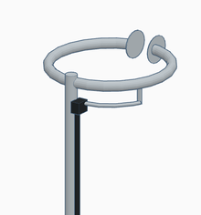

A halo antenna, or halo, is a horizontally polarized, omnidirectional 1⁄2 wavelength dipole antenna, which has been bent into a loop with a small break on the side of the loop directly opposite the feed point. The dipole ends are close but do not meet, and may have an air capacitor between them as needed to establish resonance. Early halo antennas[1] used two or more parallel loops, modeled after a 1943 patent[2] which was a folded dipole[3] bent into a circle.
The two loop design broadens the SWR bandwidth and helps with impedance matching. More recent halo antennas have tended to use a single conductor fed with a gamma match. The newer approach uses less material and reduces wind load, but may be less mechanically robust, more narrow-banded, and requires a balun to prevent feed-line radiation. The gamma match is not an essential feature, however: There are other, uncommon methods of feeding halos.
Halo antennas vs. other loop antennas
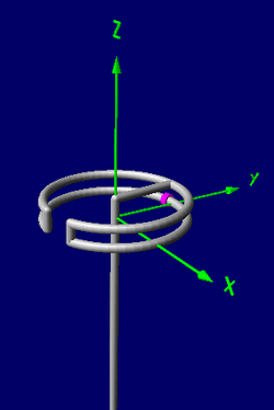
A halo antenna is distinct from a full-wave loop, which is double its size or larger, whose element is a complete loop, with no breaks. Further, full-wave loops radiate predominantly perpendicular to the plane of the loop at their lowest frequency, whereas halos radiate mostly in the loop plane, with some radiation in the perpendicular direction (Z-axis, in the diagram).
A halo antenna is distinct from the small-loop antenna in size,[lower-alpha 1] radiation pattern, and radiation resistance, or efficiency. Halos are customarily operated with the plane of the loop oriented horizontally, parallel to the ground, whereas small-loop antennas often are oriented vertically. A small-loop antenna designed for transmitting is usually is about 1⁄4 wave – half the size of a halo built for the same frequency – or a bit smaller. A small-loop can be at most a little less than 1⁄3 wave in circumference, or 2⁄3 of the size of a halo, and becomes increasingly difficult to tune as it approaches that maximum.
The current profile of a small loop is uniform or very nearly so, whereas the current on the halo antenna is sinusoidal. Almost all of the current in a halo antenna is on the side opposite the break in the loop, which is usually also the loop's feed-point. The part of the halo near the split has high voltages, but carries essentially no current and produces no radiation. The part opposite that gap is the part that radiates, and tends to radiate slightly more towards the split in the loop. Because a 1⁄4 wave small loop has the essentially the same current flowing in the entire loop it radiates in the plane of the loop uniformly, with no preferred direction in that plane.
Unlike full-wave loops, halo antennas do not produce much radiation perpendicular to the plane of the loop but do produce some; their greatest radiation is in the plane of the loop. Full wave loops produce their highest radiation perpendicular to the loop and none in the plane of the loop. Small loops are the opposite: They produce their greatest radiation in the plane of the loop, and none in the perpendicular direction. Halo antennas’ radiation pattern, like their size, falls inbetween large and small loops, although somewhat closer to small-loops.
Size is relative
Since antenna size is measured in multiples of wavelengths, a halo antenna with sufficient capacitance to operate at half its design frequency will function as a small-loop antenna; likewise, a small-loop fed with a signal at approximately double its maximum design frequency will function as a halo antenna, if its capacitance can be lowered enough to resonate.
In that sense – even though built to deal with different practical constraints – the two types of loop antenna are nearly identical. The only two issues are
- how well the loop + impedance matching system + radio can accommodate the reactance at a frequency the antenna was not designed for
- whether the capacitance across the halo’s gap (there is always some) is enough to allow a near-continuous current around the loop at below-design frequencies.
Advantages of a halo antenna
- When constructed correctly, the antenna will present a good match to 50 Ohm coaxial cable with a low SWR.[4]
- Towards the horizon, the pattern is omnidirectional to within 3 dB or less. Making the loop smaller and adding more capacity between the element tips evens out the gain while reducing upward radiation.
- The radiating element of the halo is grounded, which tends to reduce static buildup, an advantage shared by many antennas fed with a gamma match.
- On the VHF bands and above, the physical diameter of a halo is small enough to be effectively used as a mobile antenna.
- Halos may be stacked for additional gain. This reduces the high angle radiation, but has little or no effect on the shape of the radiation pattern in the plane of the antenna. High angle radiation is not useful for VHF work except for space communications.
- Halos pick up less ignition noise from vehicles when mounted atop vehicle roofs than whip antennas.[5]
- Halo antennas have lower voltages across their gaps than small-loop antennas fed with the same power, reducing problems with arcing and electric shock, and radiate more efficiently than small loops.
Disadvantages of a halo antenna
- Radiation from horizontal halos has almost no vertical component. One can expect 3–20 dB of signal loss when working with stations using vertical polarization.[5]
- For mobile use, the halo is rather conspicuous compared to the much more common vertical whip antenna, and may attract unwanted attention.
- The halo is a rigid structure and may suffer damage from tree branches or other obstacles in mobile operation.
- A halo antenna can function as designed – as a resonant half-wave antenna – only at one frequency, limiting its use to a single band, or only a part of one band. A small transmitting loop can be re-tuned to a range of frequencies typically wider than 2:1, approaching 3:1, which can cover two or three different amateur bands.
- A halo antenna is not as efficient for distance contacts via skywave as a horizontal small loop, other things being equal, since more of its signal is sent upward instead of outward, wasting signal power “warming the clouds”.
Notes
- ↑ Note carefully that for pattern and performance measurement, antenna size is measured as a fraction (or multiple) of the length of waves passing through it, for all antenna types; hence any one antenna’s effective “size” changes depending on the frequency the attached radio is operating on.
References
- ↑ Stites, Francis H. (October 1947). "A Halo for Six Meters". QST Magazine, p. 24.
- ↑ US patent 2324462, Leeds, L.M. & Scheldorf, M.W., "High frequency antenna system", issued 1943-07-13, assigned to General Electric Company
- ↑ "Folded Dipole". Antenna Theory.
- ↑ Danzer, Paul (Sep 2004). QST Magazine, p. 37
- 1 2 Tildon, Edward P. (Dec 1956). "Polarization Effects in V.H.F. Mobile". QST Magazine, p. 11–13.
External links
- "Construct a halo antenna for two meters". kr1st.com.
- "Another two meter VHF loop design". fedler.com.