Transmitter
In electronics and telecommunications, a transmitter or radio transmitter is an electronic device which produces radio waves with an antenna. The transmitter itself generates a radio frequency alternating current, which is applied to the antenna. When excited by this alternating current, the antenna radiates radio waves.
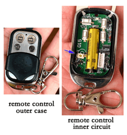
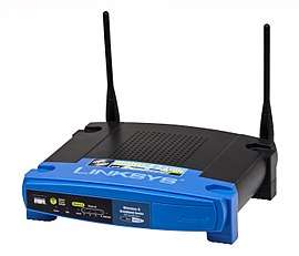
Transmitters are necessary component parts of all electronic devices that communicate by radio, such as radio and television broadcasting stations, cell phones, walkie-talkies, wireless computer networks, Bluetooth enabled devices, garage door openers, two-way radios in aircraft, ships, spacecraft, radar sets and navigational beacons. The term transmitter is usually limited to equipment that generates radio waves for communication purposes; or radiolocation, such as radar and navigational transmitters. Generators of radio waves for heating or industrial purposes, such as microwave ovens or diathermy equipment, are not usually called transmitters, even though they often have similar circuits.
The term is popularly used more specifically to refer to a broadcast transmitter, a transmitter used in broadcasting, as in FM radio transmitter or television transmitter. This usage typically includes both the transmitter proper, the antenna, and often the building it is housed in.
Description
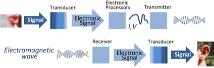
A transmitter can be a separate piece of electronic equipment, or an electrical circuit within another electronic device. A transmitter and a receiver combined in one unit is called a transceiver. The term transmitter is often abbreviated "XMTR" or "TX" in technical documents. The purpose of most transmitters is radio communication of information over a distance. The information is provided to the transmitter in the form of an electronic signal, such as an audio (sound) signal from a microphone, a video (TV) signal from a video camera, or in wireless networking devices, a digital signal from a computer. The transmitter combines the information signal to be carried with the radio frequency signal which generates the radio waves, which is called the carrier signal. This process is called modulation. The information can be added to the carrier in several different ways, in different types of transmitters. In an amplitude modulation (AM) transmitter, the information is added to the radio signal by varying its amplitude. In a frequency modulation (FM) transmitter, it is added by varying the radio signal's frequency slightly. Many other types of modulation are also used.
The radio signal from the transmitter is applied to the antenna, which radiates the energy as radio waves. The antenna may be enclosed inside the case or attached to the outside of the transmitter, as in portable devices such as cell phones, walkie-talkies, and garage door openers. In more powerful transmitters, the antenna may be located on top of a building or on a separate tower, and connected to the transmitter by a feed line, that is a transmission line.
History
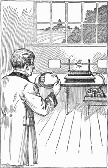
The first primitive radio transmitters (called Hertzian oscillators) were built by German physicist Heinrich Hertz in 1887 during his pioneering investigations of radio waves. These generated radio waves by a high voltage spark between two conductors. Beginning in 1895, Guglielmo Marconi developed the first practical radio communication systems using these transmitters. Spark transmitters couldn't transmit audio (sound) and instead transmitted information by telegraphy, the operator tapped on a telegraph key which turned the transmitter on and off to produce pulses of radio waves spelling out text messages in Morse code. These spark-gap transmitters were used during the first three decades of radio (1887-1917), called the wireless telegraphy or "spark" era. Because they generated damped waves, spark transmitters were electrically "noisy". Their energy was spread over a broad band of frequencies, creating radio noise which interfered with other transmitters. Two short-lived competing transmitter technologies came into use after the turn of the century, which were the first continuous wave transmitters: the Alexanderson alternator and Poulsen arc transmitters, which were used into the 1920s.
All these early technologies were replaced by vacuum tube transmitters in the 1920s, which used the feedback oscillator invented by Edwin Armstrong and Alexander Meissner around 1912, based on the Audion (triode) vacuum tube invented by Lee De Forest in 1906. Vacuum tube transmitters were inexpensive and produced continuous waves, and could be easily modulated to transmit audio (sound) using amplitude modulation (AM). This made AM radio broadcasting possible, which began in about 1920. Practical frequency modulation (FM) transmission was invented by Edwin Armstrong in 1933, who showed that it was less vulnerable to noise and static than AM. The first FM radio station was licensed in 1937. Experimental television transmission had been conducted by radio stations since the late 1920s, but practical television broadcasting didn't begin until the late 1930s. The development of radar during World War II motivated the evolution of high frequency transmitters in the UHF and microwave ranges, using new active devices such as the magnetron, klystron, and traveling wave tube.
The invention of the transistor allowed the development in the 1960s of small portable transmitters such as wireless microphones, garage door openers and walkie-talkies. The development of the integrated circuit (IC) in the 1970s made possible the current proliferation of wireless devices, such as cell phones and laptops, in which integrated digital transmitters and receivers in wireless modems operate automatically, in the background, to exchange data with wireless networks. In recent years, the need to conserve crowded radio spectrum bandwidth has driven the development of new types of transmitters such as spread spectrum and cognitive radio.
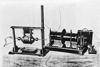 Guglielmo Marconi's spark gap transmitter, with which he performed the first experiments in practical radio communication in 1895-1897
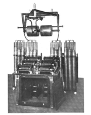 High power spark gap transmitter in Australia around 1910.
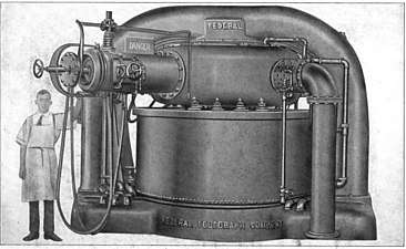 1 MW US Navy Poulsen arc transmitter which generated continuous waves using an electric arc in a magnetic field, a technology used from 1903 until the 1920s.
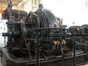 An Alexanderson alternator, a huge rotating machine used as a radio transmitter for a short period from about 1910 until vacuum tube transmitters took over in the 1920s
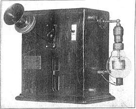 One of the first vacuum tube AM radio transmitters, built by Lee De Forest in 1914. The early Audion (triode) tube is visible at right.
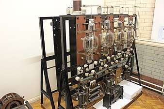 One of the BBC's first broadcast transmitters, early 1920s, London. The 4 triode tubes, connected in parallel to form an oscillator, each produced around 4 kilowatts with 12 thousand volts on their anodes.
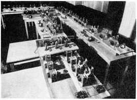 Armstrong's first experimental FM broadcast transmitter W2XDG, in the Empire State Building, New York City, used for secret tests 1934-1935. It transmitted on 41 MHz at a power of 2 kW.
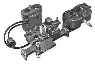 Transmitter assembly of a 20 kW, 9.375 GHz air traffic control radar, 1947. The magnetron tube mounted between two magnets (right) produces microwaves which pass from the aperture (left) into a waveguide which conducts them to the dish antenna.
Operation
Electromagnetic waves are radiated by electric charges undergoing acceleration.[1][2] Radio waves, electromagnetic waves of radio frequency, are generated by time-varying electric currents, consisting of electrons flowing through a conductor which are changing their velocity or direction and thus accelerating.[2] An alternating current flowing back and forth in a metal conductor (an antenna) will create an oscillating magnetic field around the conductor. The alternating voltage will also charge the ends of the conductor alternately positive and negative, creating an oscillating electric field around the conductor. If the frequency of the oscillations is high enough, in the radio frequency range above about 20 kHz, the oscillating coupled electric and magnetic fields will radiate away from the antenna into space as an electromagnetic wave, a radio wave.
A radio transmitter is an electronic circuit which transforms electric power from a power source into a radio frequency alternating current to apply to the antenna, and the antenna radiates the energy from this current as radio waves. The transmitter also impresses information such as an audio or video signal onto the radio frequency current to be carried by the radio waves. When they strike the antenna of a radio receiver, the waves excite similar (but less powerful) radio frequency currents in it. The radio receiver extracts the information from the received waves.
Components
A practical radio transmitter usually consists of these parts:
- A power supply circuit to transform the input electrical power to the higher voltages needed to produce the required power output.
- An electronic oscillator circuit to generate the radio frequency signal. This usually generates a sine wave of constant amplitude called the carrier wave, because it serves to "carry" the information through space. In most modern transmitters, this is a crystal oscillator in which the frequency is precisely controlled by the vibrations of a quartz crystal.
- A modulator circuit to add the information to be transmitted to the carrier wave produced by the oscillator. This is done by varying some aspect of the carrier wave. The information is provided to the transmitter either in the form of an audio signal, which represents sound, a video signal which represents moving images, or for data in the form of a binary digital signal. Different types of transmitters use different modulation methods to transmit information:
- In an AM (amplitude modulation) transmitter the amplitude (strength) of the carrier wave is varied in proportion to the modulation signal.
- In an FM (frequency modulation) transmitter the frequency of the carrier is varied by the modulation signal.
- In an FSK (frequency-shift keying) transmitter, which transmits digital data, the frequency of the carrier is shifted between two frequencies which represent the two binary digits, 0 and 1.
- Many other types of modulation are also used. In large transmitters the oscillator and modulator together are often referred to as the exciter.
- A radio frequency (RF) amplifier to increase the power of the signal, to increase the range of the radio waves.
- An impedance matching (antenna tuner) circuit to match the impedance of the transmitter to the impedance of the antenna (or the transmission line to the antenna), to transfer power efficiently to the antenna. If these impedances are not equal, it causes a condition called standing waves, in which the power is reflected back from the antenna toward the transmitter, wasting power and sometimes overheating the transmitter.
In higher frequency transmitters, in the UHF and microwave range, free running oscillators are unstable at the output frequency. Older designs used an oscillator at a lower frequency, which was multiplied by frequency multipliers to get a signal at the desired frequency. Modern designs more commonly use an oscillator at the operating frequency which is stabilized by phase locking to a very stable lower frequency reference, usually a crystal oscillator.
Legal restrictions
In most parts of the world, use of transmitters is strictly controlled by law because of the potential for dangerous interference with other radio transmissions (for example to emergency communications). Transmitters must be licensed by governments, under a variety of license classes depending on use such as broadcast, marine radio, Airband, Amateur and are restricted to certain frequencies and power levels. A body called the International Telecommunications Union (ITU) allocates the frequency bands in the radio spectrum to various classes of users. In some classes, each transmitter is given a unique call sign consisting of a string of letters and numbers which must be used as an identifier in transmissions. The operator of the transmitter usually must hold a government license, such as a general radiotelephone operator license, which is obtained by passing a test demonstrating adequate technical and legal knowledge of safe radio operation.
An exception is made allowing the unlicensed use of low-power short-range transmitters in devices such as cell phones, cordless telephones, wireless microphones, walkie-talkies, Wifi and Bluetooth devices, garage door openers, and baby monitors. In the US, these fall under Part 15 of the Federal Communications Commission (FCC) regulations. Although they can be operated without a license, these devices still generally must be type-approved before sale.
See also
References
- ↑ Serway, Raymond; Faughn, Jerry; Vuille, Chris (2008). College Physics, 8th Ed. Cengage Learning. p. 714. ISBN 0495386936.
- 1 2 Ellingson, Steven W. (2016). Radio Systems Engineering. Cambridge University Press. pp. 16–17. ISBN 1316785165.
External links
| Look up transmitter in Wiktionary, the free dictionary. |
- International Telecommunication Union
- Jim Hawkins' Radio and Broadcast Technology Page
- WCOV-TV's Transmitter Technical Website
- Major UK television transmitters including change of group information, see Transmitter Planning section.
- Details of UK digital television transmitters