Incremental encoder
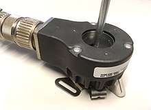
An incremental encoder is a linear or rotary electromechanical device that has two output signals, A and B, which issue pulses when the device is moved.[1] Many incremental encoders have an additional output signal, typically designated index[2] or Z,[3] which indicates the encoder is located at a particular reference position. Also, some encoders provide a status output (typically designated "alarm"[4]) that indicates internal fault conditions such as a bearing failure or sensor malfunction.
An incremental encoder does not indicate absolute position; it only reports incremental changes in position.[3] Consequently, to determine absolute position at any particular moment, it is necessary to send the encoder signals to an incremental encoder interface, which in turn will "track" and report the encoder's absolute position.
Incremental encoders report position changes without being prompted to do so, and they convey this information at data rates which are orders of magnitude faster than those of most types of absolute encoders. The resulting, very low data latency of an incremental encoder allows it to be used to monitor the position of a high speed mechanism in real time -- a capability lacking in most types of absolute encoders. Because of this, incremental encoders are commonly used in applications that require precise measurement of position and velocity.
Quadrature outputs
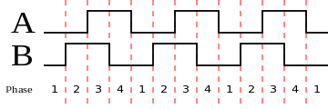
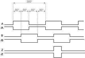
The pulses emitted from an incremental encoder's A and B outputs are quadrature-encoded, meaning that when the encoder is moving at a constant velocity, the duty cycle of each pulse is 50% (i.e., the waveform is a square wave) and there is a 90 degree phase difference between A and B.[2] At any particular time, the phase difference will be positive or negative depending on the encoder's direction of movement. In the case of a rotary encoder, the phase difference is +90° for clockwise rotation and -90° for counter-clockwise rotation, or vice versa, depending on the device design.
The frequency of the pulses on the A or B output is directly proportional to the encoder's velocity (rate of position change); higher frequencies indicate rapid movement, whereas lower frequencies indicate slower speeds.[1] Static, unchanging signals are output on A and B when the encoder is motionless. In the case of a rotary encoder, the frequency indicates the speed of the encoder's shaft rotation, and in linear encoders the frequency indicates the speed of linear traversal.
- Conceptual drawings of sensing mechanisms
 Rotary encoder, with corresponding A/B signal states shown on the right
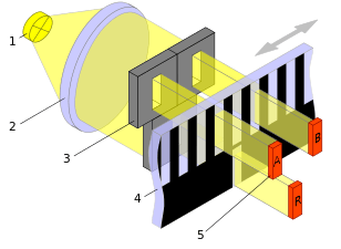 Linear encoder; the R signal indicates the encoder is located at its reference position
Resolution
The resolution of an incremental encoder is a measure of the precision of the position information it produces. Encoder resolution is typically specified in terms of output pulses per unit displacement. In the case of rotary encoders, resolution is specified as the number of pulses per revolution (PPR) or cycles per revolution (CPR)[3], whereas linear encoder resolution is typically specified as the number of pulses issued for a particular linear traversal distance (e.g., 1000 pulses per millimeter).
This is in contrast to the measurement resolution of the encoder, which is the smallest position change that the encoder can detect. For example, a 1000 pulse-per-millimeter linear encoder has a measurement resolution of one micrometer.
Signal types
Incremental encoders employ various types of electronic circuits to drive (transmit) their output signals, and manufacturers often have the ability to build a particular encoder model with any of several driver types. Commonly available driver types include open collector, mechanical, push-pull and differential RS-422.
Open collector
Open collector drivers operate over a wide range of signal voltages and often can sink significant output current, making them useful for directly driving current loops, opto-isolators and fiber optic transmitters.
An open-collector output must be connected to a positive DC voltage through a pull-up resistor. Some encoders provide an internal resistor for this purpose; others do not and thus require an external pull-up resistor. In the latter case, the resistor typically is located near the encoder interface to improve noise immunity.
The encoder's high-level logic signal voltage is determined by the voltage applied to the pull-up resistor, whereas the low-level output current is determined by both the signal voltage and load resistance (including pull-up resistor). The load resistance and circuit capacitance act together to form a low-pass filter, which stretches (increases) the signal's rise time and thus limits its maximum frequency. For this reason, open collector drivers typically are not used when the encoder will output high frequencies.
Mechanical
Mechanical (or contact[5]) incremental encoders use sliding electrical contacts to directly generate the A and B output signals.[2] Typically, the contacts are electrically connected to signal ground so that the outputs will be "driven" low when the contacts are closed, effectively making them mechanical equivalents of open collector drivers and therefore subject to the same signal conditioning requirements (i.e. external pull-up resistor).
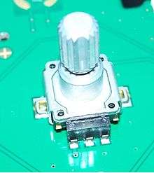
The maximum output frequency is limited by the same factors that affect open-collector outputs, and further limited by contact bounce -- which must be filtered by the encoder interface -- and by the operating speed of the mechanical contacts, thus making these devices impractical for high frequency operation. Furthermore, the contacts experience mechanical wear under normal operation, which limits the rotational life of these devices. On the other hand, mechanical encoders are relatively inexpensive because they have no internal, active electronics. Taken together, these attributes make mechanical encoders a good fit for low duty, low frequency applications. For example, PCB- and panel-mounted rotary mechanical incremental encoders are commonly used as hand-operated controls in electronic equipment.
Push-pull
Push-pull outputs (e.g., TTL) typically are used for direct interface to logic circuitry. These are well-suited to applications in which the encoder and interface are located near each other (e.g., interconnected via printed circuit conductors or short, shielded cable runs) and powered from a common power supply, thus avoiding exposure to electric fields, ground loops and transmission line effects that might corrupt the signals and thereby disrupt position tracking, or worse, damage the encoder interface.
Differential
Differential RS-422 signaling is typically preferred when the encoder will output high frequencies or be located far away from the encoder interface,[5][6] or when the encoder signals may be subjected to electric fields or common-mode voltages,[5] or when the interface must detect connectivity problems between encoder and interface. Examples of this include CMMs and CNC machinery, industrial robotics, factory automation, and motion platforms used in aircraft and spacecraft simulators.
When RS-422 outputs are employed, the encoder provides a differential conductor pair for every logic output; for example, "A" and "/A" are commonly-used designations for the active-high and active-low differential pair comprising the encoder's "A" logic output. Consequently, the encoder interface must provide RS-422 line receivers to convert the incoming RS-422 pairs to single-ended logic.[5]
Principal applications
Position tracking

Unlike absolute encoders, an incremental encoder does not keep track of, nor do its outputs indicate the current encoder position; it only reports incremental changes in position.[3] Consequently, to determine the encoder's position at any particular moment, it is necessary to provide external electronics which will "track" the position. This external circuitry, which is known as an incremental encoder interface, tracks position by counting the pulse edges emitted from the encoder's A and B outputs.
As it receives each edge, an encoder interface takes into account the phase relationship between A and B and, depending on the sign of the phase angle, may either count up or down. The counter's current, accumulated "counts" value indicates the distance traveled since tracking began. This method ensures accurate position tracking in bidirectional applications and, in unidirectional applications, prevents false counts that would otherwise result from vibration or mechanical dithering near an AB code transition.
Often the encoder counts must be expressed in units such as meters, miles or revolutions. In such cases, the software will multiply the counts by an appropriate constant to convert it to the desired units. For example, in the case of a linear incremental encoder that produces 8000 counts per millimeter of travel, the software would multiply the counts by 1/8000 to convert it to millimeters.
Homing
In order for an encoder interface to track and report absolute position, the encoder counts must be correlated to a reference position in the mechanical system to which the encoder is attached. This is commonly done by "homing" the system, which consists of moving the mechanical system (and encoder) until it aligns with a reference position, and then jamming the associated absolute position counts into the encoder interface's counter. Another common method is jam a reference value into the counter upon receiving a pulse from the encoder's "index" output, if available.
Speed measurement

Incremental encoders are commonly used to measure the speed of mechanical systems. This may be done for monitoring purposes or to provide feedback for motion control, or both.[5] Widespread applications of this include speed control of radar antenna rotation and material conveyors, and motion control in robotics, CMM and CNC machines.
Incremental encoder interfaces are primarily concerned with tracking mechanical displacement and usually do not directly measure speed. Consequently, speed must be indirectly measured, either by timing the A or B pulse width (or cycle time) or by counting pulses.[2] In the latter case, the pulses are typically counted by an encoder interface and speed is derived from the resulting position information.
In many cases, this derivation is performed by software which is executing on a computer. Under the direction of the software, the computer — which has access to the encoder interface — will read the position counts from the interface (i.e., "sample" the counts) and then, at some later time, sample the counts again. Each sample is effectively an ordered pair (C,T) in which C is the position counts and T is the time when the sample was acquired. Using the two acquired samples, (C0,T0) and (C1,T1), the average speed is then calculated: speed = (C1 - C0) / (T1 - T0).
The resulting "raw" speed value is expressed as counts per unit time (e.g., counts per second). In practice, however, it is often necessary to express the speed in standardized units (e.g., meters/second, revolutions/minute, miles/hour). In such cases, the software will take into account the relationship between counts and desired distance units, as well as the ratio of the sampling period to desired time units, and translate the raw speed accordingly. For example, in the case of a rotary incremental encoder that produces 4096 counts per revolution, which is being sampled once per second, the software would multiply the raw speed by 60/4096 to convert it to revolutions/minute.
When measuring speed in this way, the measurement resolution is proportional to both the encoder resolution and the sampling period (the elapsed time between the two samples); measurement resolution will become higher as the sampling period increases.[2]
Incremental encoder interface
An incremental encoder interface is an electronic circuit that receives signals from an incremental encoder, processes the signals to produce absolute position and other information, and makes the resulting information available to external circuitry.
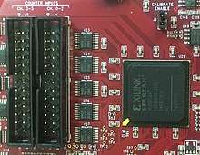
Incremental encoder interfaces are implemented in a variety of ways, including as ASICs, as IP blocks within FPGAs, as dedicated peripheral interfaces in microcontrollers and, when high count rates are not required, as software managed bit-bang interfaces.
Regardless of the implementation, the interface must sample the encoder's A and B output signals frequently enough to detect every AB state change before the next state change occurs. Upon detecting a state change, it will increment or decrement the position counts based on whether A leads or trails B. This is typically done by storing a copy of the previous AB state and, upon state change, using the current and previous AB states to determine movement direction.
Line receivers
Single-ended
Incremental encoder interfaces typically employ Schmitt trigger inputs to receive signals from encoders that have single-ended (e.g., push-pull, open collector) outputs. This type of line receiver inherently rejects low-level noise (by means of its input hysteresis) and protects downstream circuitry from invalid (and possibly destructive) logic signal levels.
Differential
In mission-critical systems, an encoder interface may be required to detect loss of input signals due to encoder power loss or signal driver failure, cable fault or cable disconnect. This is usually accomplished by using an encoder that has RS-422 outputs, and by employing enhanced RS-422 line receivers in the encoder interface which sense the absence of driven input signals and report this condition via an "open-circuit" status output. In normal operation, glitches (brief pulses) may appear on the status outputs during input state transitions. Typically, the encoder interface will filter the status signals to prevent these glitches from being erroneously interpreted as faults. Depending on the interface, subsequent processing may include generating an interrupt request upon loss of receiver signal, and forwarding fault signals to the application for error logging or failure analysis.
Input filter
In many cases an encoder interface must filter the incoming encoder signals before further processing them. This may be required to reject low-level noise and brief, large-amplitude noise spikes commonly found in motor applications[7] and, in the case of mechanical-type encoders, to debounce A and B to avoid count errors due to mechanical contact bounce.
Hardware-based interfaces often provide programmable filters for the encoder signals, which provide a wide range of filter settings and thus allow them to debounce contacts or suppress transients resulting from noise or slowly slewing signals, as needed. In bit-bang interfaces, A and B typically are connected to GPIOs that are sampled (via polling or edge interrupts) and debounced by software.
Quadrature decoder
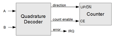
Incremental encoder interfaces commonly use a quadrature decoder to convert the A and B signals into the direction and count enable (clock enable) signals needed for controlling a synchronous, bidirectional (up- and down-counting) binary counter.
Typically, a quadrature decoder is implemented as a finite-state machine (FSM) which simultaneously samples the A and B signals and thus produces amalgamate "AB" samples. As each new AB sample is acquired, the FSM will store the previous AB sample for later analysis. The FSM evaluates the differences between the new and previous AB states and generates direction and count enable signals as appropriate for the detected AB state sequence.[7]
| Description | AB state | Outputs | |||||
|---|---|---|---|---|---|---|---|
| Previous | Current | CE | DIR | ERR | |||
| x1 | x2 | x4 | |||||
| Moved one increment in "forward" direction (A leads B) | 00 | 10 | 1 | 1 | 1 | 1 | 0 |
| 10 | 11 | 0 | 0 | ||||
| 11 | 01 | 1 | |||||
| 01 | 00 | 0 | |||||
| Moved one increment in "reverse" direction (B leads A) | 00 | 01 | 0 | 0 | |||
| 01 | 11 | 1 | |||||
| 11 | 10 | 0 | |||||
| 10 | 00 | 1 | 1 | ||||
| No detected movement | 00 | 00 | 0 | X | |||
| 01 | 01 | ||||||
| 10 | 10 | ||||||
| 11 | 11 | ||||||
| Moved an indeterminate number of increments | 00 | 11 | 1 | ||||
| 01 | 10 | ||||||
| 10 | 01 | ||||||
| 11 | 00 | ||||||
In any two consecutive AB samples, the logic state of A or B may change or both states may remain unchanged, but in normal operation the A and B states will never both change. When neither A nor B changes, the quadrature decoder assumes the encoder has not moved and so it negates its count enable output, thereby causing the counts to remain unchanged. When just A or B changes state, the quadrature decoder assumes the encoder has moved one increment of its measurement resolution and, accordingly, it may assert its count enable output to allow the counts to change, and assert or negate its direction output to cause the counts to increment or decrement (or vice versa).
Errors
If both the A and B logic states change in consecutive AB samples, the clock decoder has no way of determining how many increments, or in what direction the encoder has moved. This can happen if the encoder speed is too fast for the quadrature decoder to process (i.e., the rate of AB state changes exceeds the quadrature decoder's sampling rate; see Nyquist rate) or if the A or B signal is noisy.
In most encoder applications this is a catastrophic event because the counter no longer provides an accurate indication of encoder position. Consequently, many quadrature decoders output an additional error signal which is asserted when the A and B states change simultaneously. Due to the severity and time-sensitive nature of this condition, the error signal is often connected to an interrupt request.
Clock multiplier
A quadrature decoder does not necessarily allow the counts to change for every incremental position change. When a decoder detects an incremental position change (due to a transition of A or B, but not both), it may allow the counts to change or it may inhibit counting, depending on the AB state transition and the decoder's clock multiplier.
The clock multiplier of a quadrature decoder is so named because it results in a count rate which is a multiple of the A or B pulse frequency. Depending on the decoder's design, the clock multiplier may be hardwired into the design or it may be run-time configurable via input signals.
The clock multiplier value may be one, two or four (typically designated "x1", "x2" and "x4", or "1x", "2x" and "4x"[8]). In the case of a x4 multiplier, the counts will change for every AB state change, thereby resulting in a count rate equal to four times the A or B frequency. The x2 and x1 multipliers allow the counts to change on some, but not all AB state changes, as shown in the quadrature decoder state table above (note: this table shows one of several possible implementations for x2 and x1 multipliers; other implementations may enable counting at different AB transitions).
Position reporting
From an application's perspective, the fundamental purpose of an incremental encoder interface is to report position information on demand. Depending on the application, this may be as simple as allowing the computer to read the position counter at any time. To facilitate this, an encoder interface will typically employ a sample register. When the computer demands position information, the interface will sample the position counter (i.e., copy the current position counts to the sample register) and then the computer will read the counts from the sample register. This mechanism results in atomic operation and thus ensures the integrity of the sample data, which might otherwise be at risk (e.g., if the sample size exceeds the computer's word size).[1]
Triggered sampling
At higher encoder speeds and resolutions, the computer may not be able to programatically (via programmed I/O) acquire position information with adequate timing precision. To overcome this limitation, it is common for an incremental encoder interface to implement hardware-triggered sampling, which enables it to sample the position counter at precisely-controlled times as dictated by a trigger input signal.[1] This is important when the position must be sampled at particular times or in response to physical events, and essential in applications such as multi-axis motion control and CMM, in which the position counters of multiple encoder interfaces (one per axis) must be simultaneously sampled.
Hardware-triggered sampling is usually asynchronous with respect to software execution. Consequently, when the position counter is sampled in response to a trigger signal, the computer must be notified (typically via interrupt) that a sample is available. Often, the computer also must know when the sample was acquired and, if the interface has multiple trigger inputs, which signal triggered the sample acquisition. To satisfy these requirements, the interface typically will include a timestamp and trigger information in every sample.
Consecutive sampling triggers may occur faster than the computer can process the resulting samples. When this happens, the information in the sample register will be overwritten before it can be read by the computer, resulting in data loss. To avoid this problem, some incremental encoder interfaces provide a FIFO buffer for samples.[1] As each sample is acquired, it is stored in the FIFO. When the computer demands a sample, it is allowed to read the oldest sample in the FIFO.
References
| Wikimedia Commons has media related to Incremental encoders. |
- 1 2 3 4 5 Sensoray. "Introduction to Incremental Encoders". Retrieved 18 July 2018.
- 1 2 3 4 5 Craig, K. "Optical Encoders" (PDF). Retrieved 25 July 2018.
- 1 2 3 4 "The Basics of How an Encoder Works" (PDF). Encoder Products Company. Retrieved 23 July 2018.
- ↑ "Encoder Basics" (PDF). ICS A/S.
- 1 2 3 4 5 "Encoder Primer" (PDF). NASA Infrared Telescope Facility (IRTF). Institute for Astronomy, University of Hawaii. Retrieved 17 August 2018.
- ↑ "3 Steps to Specifying the Correct Encoder Output Type". Encoder Products. Retrieved 20 August 2018.
- 1 2 "Quadrature Decoder/Counter Interface ICs" (PDF). Agilent Technologies. Retrieved 20 August 2018.
- ↑ "Addressing encoder error". Machine Design. Retrieved 20 August 2018.