Pull-up resistor
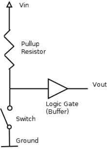
In electronic logic circuits, a pull-up resistor is a resistor used to ensure a known state for a signal. It is typically used in combination with components such as switches and transistors, which physically interrupt the connection of subsequent components to ground. The pull-up resistor then ensures a well-defined voltage (i.e. VCC) across the latter during interruption.
An open switch is not equivalent to a component with infinite impedance, since in the former case, the stationary voltage in any loop in which it is involved can no longer be determined by Kirchhoff's laws. Consequently, the voltages across those critical components (such as the logic gate in the example on the right) which are only in loops involving the open switch are undefined, too.
A pull-up resistor effectively establishes an additional loop over the critical components, ensuring that the voltage is well-defined even when the switch is open.
For a pull-up resistor to only serve this one purpose and not interfere with the circuit otherwise, it is assumed that the critical components have infinite or sufficiently high impedance, which is guaranteed for example for logic gates made from FETs. In this case, when the switch is open, the voltage across a pull-up resistor with sufficiently low impedance vanishes to the effect that it looks like a wire to VCC. On the other hand, when the switch is closed, the pull-up resistor must have sufficiently high impedance in comparison to the closed switch to not affect the connection to ground. Together, these two conditions can be used to derive an appropriate value for the impedance of the pull-up resistor but usually, only a lower bound is derived assuming that the critical components do indeed have infinite impedance.
A pull-down resistor works in the same way but is connected to ground. It holds the logic signal at a low logic level when no other active device is connected.
Applications
A pull-up resistor may be used when interfacing logic gates to inputs. For example, an input signal may be pulled by a resistor, then a switch or jumper strap can be used to connect that input to ground. This can be used for configuration information, to select options or for troubleshooting of a device.
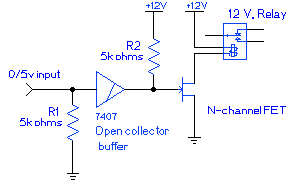
Pull-up resistors may be used at logic outputs where the logic device cannot source current such as open-collector TTL logic devices. Such outputs are used for driving external devices, for a wired-OR function in combinational logic, or for a simple way of driving a logic bus with multiple devices connected to it. For example, the circuit shown on the right uses 0 V logic level inputs to actuate a relay. If the input is left unconnected, pull-down resistor R1 ensures that the input is pulled down to a logic low. The 7407 TTL device, an open collector buffer, simply outputs whatever it receives as input, but as an open collector device, the output is left effectively unconnected when outputting a "1". Pull-up resistor R2 thus pulls the output all the way up to 12 V when the buffer outputs a "1", providing enough voltage to turn the power MOSFET all the way on and actuate the relay.
Pull-up resistors may be discrete devices mounted on the same circuit board as the logic devices. Many microcontrollers intended for embedded control applications have internal, programmable pull-up resistors for logic inputs so that minimal external components are needed.
Some disadvantages of pull-up resistors are the extra power consumed when current is drawn through the resistor and the reduced speed of a pull-up compared to an active current source. Certain logic families are susceptible to power supply transients introduced into logic inputs through pull-up resistors, which may force the use of a separate filtered power source for the pull-ups.
Pull-down resistors can be safely used with CMOS logic gates because the inputs are voltage-controlled. TTL logic inputs that are left un-connected inherently float high, and require a much lower valued pull-down resistor to force the input low. A standard TTL input at logic "1" is normally operated assuming a source current of 40 µA, and a voltage level above 2.4 V, allowing a pull-up resistor of no more than 50 kohms; whereas the TTL input at logic "0" will be expected to sink 1.6 mA at a voltage below 0.8 V, requiring a pull-down resistor less than 500 ohms.[1] Holding unused TTL inputs low consumes more current. For that reason, pull-up resistors are preferred in TTL circuits.
In bipolar logic families operating at 5 VDC, a typical pull-up resistor value will be 1000–5000 Ω, based on the requirement to provide the required logic level current over the full operating range of temperature and supply voltage. For CMOS and MOS logic, much higher values of resistor can be used, several thousand to a million ohms, since the required leakage current at a logic input is small.
References
- Paul Horowitz and Winfield Hill, The Art of Electronics, 2nd edition, Cambridge University Press, Cambridge, England, 1989, ISBN 0-521-37095-7
- ↑ "Quadruple 2-input positive-NAND gates" (PDF). Texas Instruments. October 2003. Retrieved 11 August 2015.