Inductance

In electromagnetism and electronics, inductance is the property of an electrical conductor by which a change in electric current through it induces an electromotive force (voltage) in the conductor. It is more accurately called self-inductance. The same property causes a current in one conductor to induce an electromotive force in nearby conductors; this is called mutual inductance.[1]
Inductance is an effect caused by the magnetic field of a current-carrying conductor acting back on the conductor. An electric current through any conductor creates a magnetic field around the conductor. A changing current creates a changing magnetic field. From Faraday's law of induction any change in magnetic flux through a circuit induces an electromotive force (voltage) across the circuit. Inductance is the ratio between this induced voltage and the rate of change of the current in the circuit


From Lenz's law, this induced voltage, or "back EMF", will be in a direction so as to oppose the change in current which created it. Thus inductance is a property of a conductor which opposes any change in current through the conductor. An inductor is an electrical component which adds inductance to a circuit. It typically consists of a coil or helix of wire.
The term inductance was coined by Oliver Heaviside in 1886.[2] It is customary to use the symbol for inductance, in honour of the physicist Heinrich Lenz.[3][4] In the SI system, the unit of inductance is the henry (H), which is the amount of inductance which causes a voltage of 1 volt when the current is changing at a rate of one ampere per second. It is named for Joseph Henry, who discovered inductance independently of Faraday.[5]
Electric circuits which are located close together, so the magnetic field created by the current in one passes through the other, are said to be inductively coupled. So a change in current in one circuit will cause the magnetic flux through the other circuit to vary, which will induce a voltage in the other circuit, by Faraday's law. The ratio of the voltage induced in the second circuit to the rate of change of current in the first circuit is called the mutual inductance between the circuits. It is also measured in henries.

History
The history of electromagnetic induction, a facet of electromagnetism, began with observations of the ancients: electric charge or static electricity (rubbing silk on amber), electric current (lightning), and magnetic attraction (lodestone). Understanding the unity of these forces of nature, and the scientific theory of electromagnetism began in the late 18th century.
Electromagnetic induction was first described by Michael Faraday in 1831.[6][7] In Faraday's experiment, he wrapped two wires around opposite sides of an iron ring. He expected that, when current started to flow in one wire, a sort of wave would travel through the ring and cause some electrical effect on the opposite side. Using a galvanometer, he observed a transient current flow in the second coil of wire each time that a battery was connected or disconnected from the first coil.[8] This current was induced by the change in magnetic flux that occurred when the battery was connected and disconnected.[9] Faraday found several other manifestations of electromagnetic induction. For example, he saw transient currents when he quickly slid a bar magnet in and out of a coil of wires, and he generated a steady (DC) current by rotating a copper disk near the bar magnet with a sliding electrical lead ("Faraday's disk").[10]
It is customary to use the symbol L for inductance, in honour of the physicist Heinrich Lenz.[11][12] In the SI system, the measurement unit for inductance is the henry, with the unit symbol H, named in honor of Joseph Henry, who discovered inductance independently of, but not before, Faraday.[13]
Source of inductance
A current flowing through a conductor generates a magnetic field around the conductor, which is described by Ampere's circuital law. The total magnetic flux through a circuit is equal to the product of the magnetic field and the area of the surface spanning the current path. If the current varies, the magnetic flux through the circuit changes. By Faraday's law of induction, any change in flux through a circuit induces an electromotive force (EMF) or voltage in the circuit, proportional to the rate of change of flux


The negative sign in the equation indicates that the induced voltage is in a direction which opposes the change in current that created it; this is called Lenz's law. The potential is therefore called a back EMF. If the current is increasing, the voltage is positive at the end of the conductor through which the current enters and negative at the end through which it leaves, tending to reduce the current. If the current is decreasing, the voltage is positive at the end through which the current leaves the conductor, tending to maintain the current. Self-inductance, usually just called inductance, is the ratio between the induced voltage and the rate of change of the current

Thus, inductance is a property of a conductor or circuit, due to its magnetic field, which tends to oppose changes in current through the circuit. The unit of inductance in the SI system is the henry (H), named after American scientist Joseph Henry, which is the amount of inductance which generates a voltage of one volt when the current is changing at a rate of one ampere per second.
All conductors have some inductance, which may have either desirable or detrimental effects in practical electrical devices. The inductance of a circuit depends on the geometry of the current path, and on the magnetic permeability of nearby materials; ferromagnetic materials with a higher permeability like iron near a conductor tend to increase the magnetic field and inductance. Any alteration to a circuit which increases the flux (total magnetic field) through the circuit produced by a given current increases the inductance, because inductance is also equal to the ratio of magnetic flux to current[14][15][16][17]

An inductor is an electrical component consisting of a conductor shaped to increase the magnetic flux, to add inductance to a circuit. Typically it consists of a wire wound into a coil or helix. A coiled wire has a higher inductance than a straight wire of the same length, because the magnetic field lines pass through the circuit multiple times, it has multiple flux linkages. The inductance is proportional to the square of the number of turns in the coil.
The inductance of a coil can be increased by placing a magnetic core of ferromagnetic material in the hole in the center. The magnetic field of the coil magnetizes the material of the core, aligning its magnetic domains, and the magnetic field of the core adds to that of the coil, increasing the flux through the coil. This is called a ferromagnetic core inductor. A magnetic core can increase the inductance of a coil by thousands of times.
If multiple electric circuits are located close to each other, the magnetic field of one can pass through the other; in this case the circuits are said to be inductively coupled. Due to Faraday's law of induction, a change in current in one circuit can cause a change in magnetic flux in another circuit and thus induce a voltage in another circuit. The concept of inductance can be generalized in this case by defining the mutual inductance of circuit and circuit as the ratio of voltage induced in circuit to the rate of change of current in circuit . This is the principle behind a transformer.


The sections below will describe self-inductance, the effect of inductance in a single conductor or circuit. Mutual inductance, inductance between circuits, is described in the section at the end.
Self-inductance and magnetic energy
If the current through a conductor with inductance is increasing, a voltage will be induced across the conductor with a polarity which opposes the current, as described above (this is in addition to any voltage drop caused by the conductor's resistance). The charges flowing through the circuit lose potential energy moving from the higher voltage to the lower voltage end. The energy from the external circuit required to overcome this "potential hill" is being stored in the increased magnetic field around the conductor. Therefore, any inductance with a current through it stores energy in its magnetic field. At any given time the power flowing into the magnetic field, which is equal to the rate of change of the stored energy , is the product of the current and voltage across the conductor[18][19][20]


From (1) above


When there is no current, there is no magnetic field and the stored energy is zero. Neglecting resistive losses, the energy (measured in joules, in SI) stored by an inductance with a current through it is equal to the amount of work required to establish the current through the inductance from zero, and therefore the magnetic field. This is given by:


If the inductance is constant over the current range, the stored energy is[18][19][20]


So therefore inductance is also proportional to how much energy is stored in the magnetic field for a given current. This energy is stored as long as the current remains constant. If the current decreases, the magnetic field will decrease, inducing a voltage in the conductor in the opposite direction, negative at the end through which current enters and positive at the end through which it leaves. This will return stored magnetic energy to the external circuit.
If ferromagnetic materials are located near the conductor, such as in an inductor with a magnetic core, the above equation is only valid for linear regions of the magnetic flux, at currents below the level at which the ferromagnetic material saturates, where the inductance is approximately constant. If the magnetic field in the inductor approaches the level at which the core saturates, the inductance will begin to change with current, and the integral equation must be used.
Inductive reactance
When a sinusoidal alternating current (AC) is passing through a linear inductance, the induced back-EMF will also be sinusoidal. If the current through the inductance is , from (1) above the voltage across it will be

![{\displaystyle v(t)=L{di \over dt}=L{d \over dt}[I_{p}\sin(2\pi ft)]=2\pi fLI_{p}\cos(2\pi ft)=2\pi fLI_{p}\sin(2\pi ft+{\pi \over 2})}](../I/m/6439b8b718a48d4e5f4a5b239cbbf18daf74a839.svg)
where
is the amplitude (peak value) of the sinusoidal current in amperes,
is the frequency of the alternating current in hertz, and
is the inductance.
Thus the amplitude (peak value) of the voltage across the inductance will be


Inductive reactance is the opposition of an inductor to an alternating current.[21] It is defined analogously to electrical resistance in a resistor, as the ratio of the amplitude (peak value) of the alternating voltage to current in the component

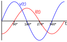
Reactance has units of ohms. It can be seen that inductive reactance of an inductor increases proportionally with frequency , so an inductor conducts less current for a given applied AC voltage as the frequency increases. Because the induced voltage is greatest when the current is increasing, the voltage and current waveforms are out of phase; the voltage peaks occur earlier in each cycle than the current peaks. The phase difference between the current and the induced voltage is radians or 90 degrees, showing that in an ideal inductor the current lags the voltage by 90°.

Calculating inductance
In the most general case, inductance can be calculated from Maxwell's equations. Many important cases can be solved using simplifications. Where high frequency currents are considered, with skin effect, the surface current densities and magnetic field may be obtained by solving the Laplace equation. Where the conductors are thin wires, self-inductance still depends on the wire radius and the distribution of the current in the wire. This current distribution is approximately constant (on the surface or in the volume of the wire) for a wire radius much smaller than other length scales.
Inductance of a straight single wire
A straight single wire has some inductance, which in our ordinary experience is intangible because it is negligibly small so it can't readily be measured at low frequencies, and its effect is not detectable. A long straight wire like an electric transmission line has substantial inductance that reduces its capacity, and there is no problem at all measuring it. As a practical matter, longer wires have more inductance, and thicker wires have less, analogous to their electrical resistance, though the relationships aren't linear nor are they the same relationships as those quantities bear to resistance. As an essential component of coils and circuits, understanding what the inductance of a wire is, is essential. Yet, there is no simple answer.
There is no unambiguous definition of the inductance of a straight wire. If we consider the wire in isolation we ignore the question of how the current gets to the wire. That current will affect the flux which is developed in the vicinity of the wire. But this flux is a part of the definition. A consequence of Maxwell's equations is that we cannot define the inductance of only a portion of a circuit, we can only define the inductance of a whole circuit, which includes how the current gets to the wire and how it returns to the source. The magnetic flux incident to the whole circuit determines the inductance of the circuit and of any part of it. The magnetic flux is an indivisible entity, yet we wish to consider only a part of it, the part incident to the wire, between whatever we define to be the "ends" of the wire.
The total low frequency inductance (internal plus external) of a straight wire is:
![{\displaystyle L_{dc}=2l\cdot \left[\ln(2l/r)-0.75\right]}](../I/m/124144886f793c9b1afe53349a2916d0848f977a.svg)
where
- is the "low-frequency" or DC inductance in nanohenries (nH or 10−9H),
- is the length of the wire in cm
- is the radius of the wire in cm.


This result is based on the assumption that the radius is much less than the length , which is commonly true.
For sufficiently high frequencies skin effects cause the internal inductance to go to zero and the inductance becomes:
![{\displaystyle L_{ac}=2l\cdot \left[\ln(2l/r)-1.00\right]}](../I/m/fd822329e74f8d8ee1c402d95a37349627b743be.svg)
See.[22]
These inductances are often referred to as "partial inductances" to indicate that they must be used with care.
In an everyday notion, one conductor of a 100m 18gauge lamp cord, stretched out straight, would have inductance of about 0.24mH.
Mutual inductance of two parallel straight wires
There are two cases to consider: current travels in the same direction in each wire, and current travels in opposing directions in the wires. Currents in the wires need not be equal, though they often are, as in the case of a complete circuit, where one wire is the source and the other the return.
Mutual inductance of two wire loops
This is the generalized case of the paradigmatic 2-loop cylindrical coil carrying a uniform low frequency current; the loops are independent closed circuits that can have different lengths, any orientation in space, and carry different currents. None-the-less, the error terms, which are not included in the integral will only be small if the geometries of the loops are mostly smooth and convex: they do not have too many kinks, sharp corners, coils, crossovers, parallel segments, concave cavities or other topological "close" deformations. A necessary predicate for the reduction of the 3-dimensional manifold integration formula to a double curve integral is that the current paths be filamentary circuits, i.e. thin wires where the radius of the wire is negligible compared to its length.
The mutual inductance by a filamentary circuit on a filamentary circuit is given by the double integral Neumann formula[23]


where
- Cm and Cn are the curves spanned by the wires.
- is the permeability of free space (4π × 10−7 H/m)
- is a small increment of the wire in circuit Cm
- is the position of in space
- is a small increment of the wire in circuit Cn
- is the position of in space


Derivation

where
- is the magnetic flux through the ith surface by the electrical circuit outlined by Cj
- is the current through the jth wire, this current creates the magnetic flux through the ith surface.
- [24]


where
- Ci is the enclosing curve of Si; and Si is undefined
- B is the magnetic field vector.
- A is the vector potential.
Stokes' theorem has been used.
Self-inductance of a wire loop
Formally, the self-inductance of a wire loop would be given by the above equation with = . However, here becomes infinite, leading to a logarithmically divergent integral.[25] This necessitates taking the finite wire radius and the distribution of the current in the wire into account. There remain the contribution from the integral over all points and a correction term,[26]


- for >
![{\displaystyle L={\frac {\mu _{0}}{4\pi }}\left[\oint _{C}\oint _{C'}{\frac {d\mathbf {x} \cdot d\mathbf {x} '}{|\mathbf {x} -\mathbf {x} '|}}\right]+{\frac {\mu _{0}}{4\pi }}lY+O}](../I/m/b7d0a2c40c908df85497f827116855b0c1ab0e51.svg)


where
- and are distances along the curves and respectively
- is the radius of the wire
- is the length of the wire
- is a constant that depends on the distribution of the current in the wire: when the current flows on the surface of the wire (total skin effect), when the current is homogeneous over the cross-section of the wire.
- is an error term when the loop has sharp corners, and when it is a smooth curve. These are small when the wire is long compared to its radius.


Inductance of a solenoid
A solenoid is a long, thin coil; i.e., a coil whose length is much greater than its diameter. Under these conditions, and without any magnetic material used, the magnetic flux density within the coil is practically constant and is given by


where is the magnetic constant, the number of turns, the current and the length of the coil. Ignoring end effects, the total magnetic flux through the coil is obtained by multiplying the flux density by the cross-section area :


When this is combined with the definition of inductance , it follows that the inductance of a solenoid is given by:


Therefore, for air-core coils, inductance is a function of coil geometry and number of turns, and is independent of current.
Inductance of a coaxial cable
Let the inner conductor have radius and permeability , let the dielectric between the inner and outer conductor have permeability , and let the outer conductor have inner radius , outer radius , and permeability . However, for a typical coaxial line application, we are interested in passing (non-DC) signals at frequencies for which the resistive skin effect cannot be neglected. In most cases, the inner and outer conductor terms are negligible, in which case one may approximate


Inductance of multilayer coils
Most practical air-core inductors are multilayer cylindrical coils with square cross-sections to minimize average distance between turns (circular cross -sections would be better but harder to form).
Magnetic cores
Many inductors include a magnetic core at the center of or partly surrounding the winding. Over a large enough range these exhibit a nonlinear permeability with effects such as magnetic saturation. Saturation makes the resulting inductance a function of the applied current.
The secant or large-signal inductance is used in flux calculations. It is defined as:

The differential or small-signal inductance, on the other hand, is used in calculating voltage. It is defined as:

The circuit voltage for a nonlinear inductor is obtained via the differential inductance as shown by Faraday's Law and the chain rule of calculus.

Similar definitions may be derived for nonlinear mutual inductance.
Mutual inductance
Derivation of mutual inductance
The inductance equations above are a consequence of Maxwell's equations. For the important case of electrical circuits consisting of thin wires, the derivation is straightforward.
In a system of K wire loops, each with one or several wire turns, the flux linkage of loop m, λm, is given by

Here Nm denotes the number of turns in loop m; Φm, the magnetic flux through loop m; and Lm,n are some constants. This equation follows from Ampere's law – magnetic fields and fluxes are linear functions of the currents. By Faraday's law of induction, we have

where vm denotes the voltage induced in circuit m. This agrees with the definition of inductance above if the coefficients Lm,n are identified with the coefficients of inductance. Because the total currents Nnin contribute to Φm it also follows that Lm,n is proportional to the product of turns NmNn.
Mutual inductance and magnetic field energy
Multiplying the equation for vm above with imdt and summing over m gives the energy transferred to the system in the time interval dt,

This must agree with the change of the magnetic field energy, W, caused by the currents.[27] The integrability condition

requires Lm,n = Ln,m. The inductance matrix, Lm,n, thus is symmetric. The integral of the energy transfer is the magnetic field energy as a function of the currents,

This equation also is a direct consequence of the linearity of Maxwell's equations. It is helpful to associate changing electric currents with a build-up or decrease of magnetic field energy. The corresponding energy transfer requires or generates a voltage. A mechanical analogy in the K = 1 case with magnetic field energy (1/2)Li2 is a body with mass M, velocity u and kinetic energy (1/2)Mu2. The rate of change of velocity (current) multiplied with mass (inductance) requires or generates a force (an electrical voltage).
Mutual inductance occurs when the change in current in one inductor induces a voltage in another nearby inductor. It is important as the mechanism by which transformers work, but it can also cause unwanted coupling between conductors in a circuit.
The mutual inductance, M, is also a measure of the coupling between two inductors. The mutual inductance by circuit i on circuit j is given by the double integral Neumann formula, see calculation techniques
The mutual inductance also has the relationship:

where
- is the mutual inductance, and the subscript specifies the relationship of the voltage induced in coil 2 due to the current in coil 1.
- N1 is the number of turns in coil 1,
- N2 is the number of turns in coil 2,
- P21 is the permeance of the space occupied by the flux.

Once the mutual inductance, M, is determined, it can be used to predict the behavior of a circuit:

where
- v1 is the voltage across the inductor of interest,
- L1 is the inductance of the inductor of interest,
- di1/dt is the derivative, with respect to time, of the current through the inductor of interest,
- di2/dt is the derivative, with respect to time, of the current through the inductor that is coupled to the first inductor, and
- M is the mutual inductance.
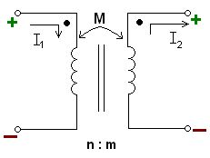
The minus sign arises because of the sense the current i2 has been defined in the diagram. With both currents defined going into the dots the sign of M will be positive (the equation would read with a plus sign instead).[28]
Coupling coefficient
The coupling coefficient is the ratio of the open-circuit actual voltage ratio to the ratio that would obtain if all the flux coupled from one circuit to the other. The coupling coefficient is related to mutual inductance and self inductances in the following way. From the two simultaneous equations expressed in the 2-port matrix the open-circuit voltage ratio is found to be:

while the ratio if all the flux is coupled is the ratio of the turns, hence the ratio of the square root of the inductances

thus,

where
- k is the coupling coefficient,
- L1 is the inductance of the first coil, and
- L2 is the inductance of the second coil.
The coupling coefficient is a convenient way to specify the relationship between a certain orientation of inductors with arbitrary inductance. Most authors define the range as 0 ≤ k < 1, but some[29] define it as −1 < k < 1. Allowing negative values of k captures phase inversions of the coil connections and the direction of the windings.[30]
Matrix representation
Mutually coupled inductors can be described by any of the two-port network parameter matrix representations. The most direct are the z parameters, which are given by
![[\mathbf {z} ]=s{\begin{bmatrix}L_{1}\ M\\M\ L_{2}\end{bmatrix}}](../I/m/a52fa6c8463d2d333ae13bfa9d566fc7f936d38d.svg)
where s is the complex frequency variable, L1 and L2 are the inductances of the primary and secondary coil, respectively, and M is the mutual inductance between the coils.
Equivalent circuits
T-circuit
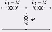
Mutually coupled inductors can equivalently be represented by a T-circuit of inductors as shown. If the coupling is strong and the inductors are of unequal values then the series inductor on the step-down side may take on a negative value.
This can be analyzed as a two port network. With the output terminated with some arbitrary impedance, Z, the voltage gain, Av, is given by,

where k is the coupling constant and s is the complex frequency variable, as above. For tightly coupled inductors where k = 1 this reduces to

which is independent of the load impedance. If the inductors are wound on the same core and with the same geometry, then this expression is equal to the turns ratio of the two inductors because inductance is proportional to the square of turns ratio.
The input impedance of the network is given by,

For k = 1 this reduces to

Thus, the current gain, Ai is not independent of load unless the further condition

is met, in which case,

and

π-circuit
Alternatively, coupled inductors can be modelled using a π equivalent circuit as shown for two inductors.
Resonant transformer
When a capacitor is connected across one winding of a transformer, making the winding a tuned circuit (resonant circuit) it is called a single-tuned transformer. When a capacitor is connected across each winding, it is called a double tuned transformer. These resonant transformers can store oscillating electrical energy similar to a resonant circuit and thus function as a bandpass filter, allowing frequencies near their resonant frequency to pass from the primary to secondary winding, but blocking other frequencies. The amount of mutual inductance between the two windings, together with the Q factor of the circuit, determine the shape of the frequency response curve. The advantage of the double tuned transformer is that it can have a narrower bandwidth than a simple tuned circuit. The coupling of double-tuned circuits is described as loose-, critical-, or over-coupled depending on the value of the coupling coefficient k. When two tuned circuits are loosely coupled through mutual inductance, the bandwidth will be narrow. As the amount of mutual inductance increases, the bandwidth continues to grow. When the mutual inductance is increased beyond the critical coupling, the peak in the frequency response curve splits into two peaks, and as the coupling is increased the two peaks move further apart. This is known as overcoupling.
Ideal transformers
When k = 1, the inductor is referred to as being closely coupled. If in addition, the self-inductances go to infinity, the inductor becomes an ideal transformer. In this case the voltages, currents, and number of turns can be related in the following way:

where
- Vs is the voltage across the secondary inductor,
- Vp is the voltage across the primary inductor (the one connected to a power source),
- Ns is the number of turns in the secondary inductor, and
- Np is the number of turns in the primary inductor.
Conversely the current:

where
- Is is the current through the secondary inductor,
- Ip is the current through the primary inductor (the one connected to a power source),
- Ns is the number of turns in the secondary inductor, and
- Np is the number of turns in the primary inductor.
The power through one inductor is the same as the power through the other. These equations neglect any forcing by current sources or voltage sources.
Self-inductance of thin wire shapes
The table below lists formulas for the self-inductance of various simple shapes made of thin cylindrical conductors (wires). In general these are only accurate if the wire radius is much smaller than the dimensions of the shape, and if no ferromagnetic materials are nearby (no magnetic core).

| Type | Inductance | Comment |
|---|---|---|
| Single layer solenoid |
The well-known Wheeler's approximation formula for current-sheet model air-core coil:[31][32] (English) (cgs) This formula gives an error no more than 1% when or . |
|
| Coaxial cable (HF) |
Outer radius Inner radius Length | |
| Circular loop[33] |
Loop radius Wire radius | |
| Rectangle made of round wire[34] |
|
Border length Wire radius |
| Pair of parallel wires |
Wire radius Distance, Length of pair | |
| Pair of parallel wires (HF) |
Wire radius Distance, : Length of pair |


![{\displaystyle \mu _{0}r\left[\ln \left({\frac {8r}{a}}\right)-2+{\frac {Y}{4}}+O\left({\frac {a^{2}}{r^{2}}}\right)\right]}](../I/m/db19cd62229c8f61cafbe3ba85e4cf9663b154c4.svg)


![{\displaystyle \qquad -\left(2-{\frac {Y}{4}}\right)\left(b+d\right)\ {\biggr ]}}](../I/m/479154b1e083be1f3b0cd6b1d3858ba30ea821b5.svg)


![{\displaystyle {\frac {\mu _{0}l}{\pi }}\left[\ln \left({\frac {d}{a}}\right)+{\frac {Y}{4}}\right]}](../I/m/6060e543d1c8407170d4750b56e55cf363aef866.svg)


- The symbol μ0 denotes the magnetic constant (4π×10−7 H/m) in SI units.
- is a constant between 0 and 1 that depends on the distribution of the current in the wire: when the current flows on the surface of the wire (total skin effect), when the current is homogeneous over the cross-section of the wire (direct current).

- is represents small term(s) that have been dropped from the formula, to make it simpler. Read the symbol “ ” as “plus small corrections on the order of” .


See also
References
- ↑ Sears and Zemansky 1964:743
- ↑ Heaviside, Oliver (1894). Electrical Papers. Macmillan and Company. p. 271.
- ↑ Glenn Elert. "The Physics Hypertextbook: Inductance". Retrieved 2016-07-30.
- ↑ Michael W. Davidson (1995–2008). "Molecular Expressions: Electricity and Magnetism Introduction: Inductance".
- ↑ "A Brief History of Electromagnetism" (PDF).
- ↑ Ulaby, Fawwaz (2007). Fundamentals of applied electromagnetics (5th ed.). Pearson:Prentice Hall. p. 255. ISBN 0-13-241326-4.
- ↑ "Joseph Henry". Distinguished Members Gallery, National Academy of Sciences. Archived from the original on 2013-12-13. Retrieved 2006-11-30.
- ↑ Michael Faraday, by L. Pearce Williams, p. 182-3
- ↑ Giancoli, Douglas C. (1998). Physics: Principles with Applications (Fifth ed.). pp. 623–624.
- ↑ Michael Faraday, by L. Pearce Williams, p. 191–5
- ↑ Glenn Elert. "The Physics Hypertextbook: Inductance". Retrieved 2016-07-30.
- ↑ Michael W. Davidson (1995–2008). "Molecular Expressions: Electricity and Magnetism Introduction: Inductance".
- ↑ "A Brief History of Electromagnetism" (PDF).
- ↑ Singh, Yaduvir (2011). Electro Magnetic Field Theory. Pearson Education India. p. 65. ISBN 8131760618.
- ↑ Wadhwa, C. L. (2005). Electrical Power Systems. New Age International. p. 18. ISBN 8122417221.
- ↑ Pelcovits, Robert A.; Josh Farkas (2007). Barron's AP Physics C. Barron's Educational Series. p. 646. ISBN 0764137107.
- ↑ Purcell, Edward M.; David J. Morin (2013). Electricity and Magnetism. Cambridge Univ. Press. p. 364. ISBN 1107014026.
- 1 2 Serway, Raymond A.; Jewett, John W. (2012). Principles of Physics: A Calculus-Based Text, 5th Ed. Cengage Learning. pp. 801–802. ISBN 1133104266.
- 1 2 Ida, Nathan (2007). Engineering Electromagnetics, 2nd Ed. Springer Science and Business Media. p. 572. ISBN 0387201564.
- 1 2 Purcell, Edward (2011). Electricity and Magnetism, 2nd Ed. Cambridge University Press. p. 285. ISBN 1139503553.
- ↑ Gates, Earl D. (2001). Introduction to Electronics. Cengage Learning. p. 153. ISBN 0766816982.
- ↑ E.B. Rosa, "The Self and Mutual Inductances of Linear Conductors", Bulletin of the Bureau of Standards, Vol.4, No.2, 1908, Page 301ff.
- ↑ Neumann, F. E. (1847). "Allgemeine Gesetze der inducirten elektrischen Ströme". Abhandlungen der Königlichen Akademie der Wissenschaften zu Berlin, aus dem Jahre 1845. 143: 1–87. Bibcode:1846AnP...143...31N. doi:10.1002/andp.18461430103.
- ↑ Jackson, J. D. (1975). Classical Electrodynamics. Wiley. pp. 176, 263.
- ↑ since for
- ↑ Dengler, R. (2016). "Self inductance of a wire loop as a curve integral". Advanced Electromagnetics. 5 (1): 1–8. Bibcode:2016AdEl....5....1D. doi:10.7716/aem.v5i1.331.
- ↑ The kinetic energy of the drifting electrons is many orders of magnitude smaller than W, except for nanowires.
- ↑ Mahmood Nahvi; Joseph Edminister (2002). Schaum's outline of theory and problems of electric circuits. McGraw-Hill Professional. p. 338. ISBN 0-07-139307-2.
- ↑ e.g. Stephen C. Thierauf, High-speed Circuit Board Signal Integrity, p. 56, Artech House, 2004 ISBN 1580538460.
- ↑ Kim, Seok; Kim, Shin-Ae; Jung, Goeun; Kwon, Kee-Won; Chun, Jung-Hoon, "Design of a reliable broadband I/O employing T-coil", Journal of Semiconductor Technology and Science, vol. 9, iss. 4, pp. 198–204
- ↑ Harold A. Wheeler, "Formulas for the Skin Effect," Proceedings of the I.R.E., September 1942, pp. 412–424
- ↑ Harold A. Wheeler, "Simple Inductance Formulas for Radio Coils," Proceedings of the I.R.E., October 1928, pp. 1398–1400.
- ↑ Elliott, R. S. (1993). Electromagnetics. New York: IEEE Press. Note: The constant −3⁄2 in the result for a uniform current distribution is wrong.
- ↑ Frederick W. Grover, Inductance Calculations: Working Formulas and Tables, Dover Publications, Inc., New York, 1946


General references
- Frederick W. Grover (1952). Inductance Calculations. Dover Publications, New York.
- Griffiths, David J. (1998). Introduction to Electrodynamics (3rd ed.). Prentice Hall. ISBN 0-13-805326-X.
- Wangsness, Roald K. (1986). Electromagnetic Fields (2nd ed.). Wiley. ISBN 0-471-81186-6.
- Hughes, Edward. (2002). Electrical & Electronic Technology (8th ed.). Prentice Hall. ISBN 0-582-40519-X.
- Küpfmüller K., Einführung in die theoretische Elektrotechnik, Springer-Verlag, 1959.
- Heaviside O., Electrical Papers. Vol.1. – L.; N.Y.: Macmillan, 1892, p. 429-560.
- Fritz Langford-Smith, editor (1953). Radiotron Designer's Handbook, 4th Edition, Amalgamated Wireless Valve Company Pty., Ltd. Chapter 10, "Calculation of Inductance" (pp. 429–448), includes a wealth of formulas and nomographs for coils, solenoids, and mutual inductance.
- F. W. Sears and M. W. Zemansky 1964 University Physics: Third Edition (Complete Volume), Addison-Wesley Publishing Company, Inc. Reading MA, LCCC 63-15265 (no ISBN).