Combined Charging System
The Combined Charging System is a standardized charging environment based on numerous standards which describe the necessary components for standardized, safe and reliable charging of electric vehicles. This charging environment encompasses charging couplers, charging communication, charging stations, the electric vehicle and various functions for the charging process as e.g. load balancing and charge authorization.
The Combined Charging System allows AC charging using the Type 1 and Type 2 connector depending on the geographical region. Further, based on this connector, the Combo 1 and Combo 2 connector have been introduced, which are based on the Type 1 and 2 connectors and are equipped with two additional DC contacts which allow High Power DC charging for shorter charging times.
Electric vehicles or electric vehicle supply equipment are CCS-capable if they support either AC or DC charging according to the standards listed by the CCS.
Automobile manufactures that support CCS include: Jaguar, Volkswagen, General Motors, BMW, Daimler, Ford, FCA, Tesla and Hyundai.[1][2]
In the United States, BMW and VW claim that the East Coast and West Coast corridors have complete CCS networks.[3]
Competing charging systems for high power DC charging include CHAdeMO (Japanese), GB/T (Chinese) and Tesla Supercharger (Tesla proprietary).
History
The revival of interest in electric cars spurred deployment of charging stations. Initially, these accessed the abundant AC mains electricity using a variety of plugs around the world. The standardization in the IEC 62196 for higher current charging connectors brought about various systems; Type 1 was used primarily in North America and Japan, while Type 2 variants elsewhere. For DC charging, the SAE and European Automobile Manufacturers Association (ACEA) made a plan to add common DC wires to the existing AC connector types such that there is only one "global envelope" that fits all DC charging stations.[4]
The proposal for a "Combined Charging System" (CCS) was published at the 15th International VDI-Congress of the Association of German Engineers on 12 October 2011 in Baden-Baden. CCS defines a single connector pattern on the vehicle side that offers enough space for a Type 1 or Type 2 connector along with space for a two-pin DC connector allowing up to 200 A. Seven car makers (Audi, BMW, Daimler, Ford, General Motors, Porsche and Volkswagen) agreed to introduce CCS in mid-2012.[5][6] The prototype implementations for up to 100 kW were shown on the EVS26 in Los Angeles in May 2012.[7] DC charging specifications in the IEC 62196-3 draft give a range up to 125 A with up to 850 V.[8]
The seven auto makers also agreed to use HomePlug GreenPHY as the communication protocol.[9] The prototype for the matching plug was developed by Phoenix Contact with the goal to withstand 10,000 connect cycles.[10] The standardization proposal was sent to the IEC in January 2011.[11] The request to use a PLC protocol for the Vehicle2Grid communication was flagged back in September 2009 in a joint presentation of BMW, Daimler and VW on California Air Resource Board ZEV Technology Symposium.[12] This competes with the CAN Bus proposal from Japan (including CHAdeMO) and China (a separate DC connector proposal), and none of their car manufacturers has signed up to CCS. However, China had been involved in early stages of the development of the extra DC pins.[10]
Volkswagen built the first public CCS quick charge station with 50 kW DC in Wolfsburg in June 2013 to test drive the upcoming VW E-Up that is to be delivered with a DC rapid charger connector for the CCS.[13] Two weeks later, BMW opened its first CCS rapid charge station to support the upcoming BMW i3.[14] Since at least the second EV World Summit in June 2013, the CHAdeMO association, Volkswagen and Nissan all advocate multi-standard DC chargers, as the additional cost of a dual-protocol station is only 5%.[15]
In Germany, the Charging Interface Initiative e. V. (CharIN) was founded by car makers and suppliers (Audi, BMW, Daimler, Mennekes, Opel, Phoenix Contact, Porsche, TÜV SÜD and Volkswagen) to promote the adoption of CCS. They noted in a press release that most cars cannot charge with more than 50 kW, so that was the first common power output of CCS stations to be built during 2015. The next step was the standardization of stations with 150 kW output that they showed in October 2015, looking to a future system with 350 kW output.[16] Volvo joined CharIN in 2016;[17] Tesla in March 2016;[18] Lucid Motors (previously Atieva) June 2016;[19] Faraday Future June 2016; Toyota March 2017.[20]
The Chevrolet Bolt/Opel Ampera-e uses this CCS standard for 50 kW quick charging.
As part of the settlement of the Volkswagen emissions scandal, VW is to spend $2 billion in the U.S. over the next 10 years on CCS and other charging infrastructure through subsidiary company Electrify America.[21] In this effort charging stations will be set up with up to 150 kW at community-based locations and with up to 350 kW at highway locations. Besides CCS also CHAdeMO charging stations will be constructed.[22]
In November 2016, Ford, Mercedes, Audi, Porsche and BMW announced building a 350 kW (up to 500 A and 920 V) charge network with 400 stations in Europe,[23] and priced at €200,000 ($210,000) each.[24]Following this announcement the joint venture IONITY was founded which started to set up its first charging park in December 2017.
Versions of CCS and System Specifications[25]
The Combined Charging System is meant to develop with the needs of customer. In its current version CCS 1.0 it covers the currently common features of AC and DC charging. As future version CCS 2.0 covers the needs which will be necessary in the near to midterm future. The specifications and underlying standards for CCS 1.0 and CCS 2.0 are described for DC charging in Table 1 and for AC charging in Table 2.
| Feature | CCS 1.0 | CCS 2.0 |
|---|---|---|
| Power | < 80 kW | < 350 kW |
| Voltage | < 400 V | 200 - 1000 V |
| Current | < 200 A | < 500 A |
| Vehicle Connector | Combo 1 or 2 (IEC 62196-3) | Combo 1 or 2 (IEC 62196-3) |
| Vehicle Inlet | Combo 1 or 2 (IEC 62196-3) | Combo 1 or 2 (IEC 62196-3) |
| Charging
Communication |
High Level Communication:
|
High Level Communication:
|
| Load Balancing | Reactive | Reactive and Scheduled |
| Charge
Authorization Mode |
External Payment | External Payment and/or Plug and
Charge (mandatory from 2020 on) |
| Charging Station | IEC 61851-23 | IEC 61851-23 |
| Feature | CCS 1.0 | CCS 2.0 |
|---|---|---|
| Vehicle Connector | Type 1 or 2 (IEC 62196-2) | Type 1 or 2 (IEC 62196-2) |
| Vehicle Inlet | Type 1 or 2 (IEC 62196-2)
Combo 1 or 2 (IEC 62196-3) |
Type 1 or 2 (IEC 62196-2)
Combo 1 or 2 (IEC 62196-3) |
| Charging
Communication |
Basic Signaling:
High Level Communication:
|
Basic Signaling:
High Level Communication:
|
| Load Balancing | With Basic Signaling only:
With High Level Communication:
|
With Basic Signaling only:
With High Level Communication:
|
| Charge
Authorization Mode |
With Basic Signaling only:
With High Level Communication:
|
With Basic Signaling only:
With High Level Communication:
|
| Charging Station | IEC 61851-1 | IEC 61851-1 |
The automotive manufacturers supporting CCS have committed themselves to migrate to CCS 2.0 in 2018. Thus it is recommended for EVSE manufacturers to also support CCS 2.0 from 2018 on.
The specifications of CCS 3.0 are not precisely defined yet. All features of previous versions shall still be given to ensure backwards compatibility. An overview of potential additional features is given:
- Reverse Power Transfer
- Inductive Charging
- Wireless charging communication
- Bus charging with "pantograph" current collector
Charging communication
Unlike the connector and inlet, which depend on the geographical location, the charging communication is the same around the globe. Generally two types of communication can be differentiated.
- Basic signaling (BS) is done using a PWM signal which is transferred over the control pilot contact (CP) according to IEC 61851-1. This communication is used for safety related functionality, indicating for example if the connector is plugged in, before contacts are made live (or energized), and if both charging station and electric vehicle are ready for charging. AC charging is possible using the PWM signal only. In this case the charging station informs the onboard charger using the duty cycle of the PWM what the maximum available current of the charging station is.
- High level communication (HLC) is done modulating a high frequency signal over the CP contact (also known as Power Line Communication or PLC) to transfer more complex information, which may be used e.g. for DC charging or as well for other services like Plug and Charge or load balancing. High level communication is based on the standard DIN SPEC 70121 and the ISO/IEC 15118-series. For DC charging DIN SPEC 70121 supports only charging powers up to 80 kW. For higher powers communication according to ISO/IEC 15118 is mandatory.
Load balancing
CCS differentiated between two methods of Load Balancing.
- Reactive load balancing allows changing the energy flow from EVSE to EV instantaneously to a specific limit.
- Scheduled load balancing supports reactive load balancing and additionally a planning of the energy flow from EVSE to EV with e.g. different power limits and cost indicators over time. It may for example be used to optimize the energy distribution in a smart grid.
Charging authorization modes
For charge authorization generally two approaches are foreseen.
- With “Plug and Charge” the user plugs in his vehicle and an automated authentication and authorization process is started without any further user interaction. Payment is performed automatically.
- With “External Payment” the user has to identify either with an RFID card at the terminal or conduct a payment with a payment card before he can proceed with charging.
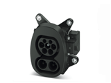
Vehicle coupler
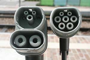
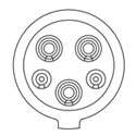
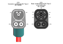
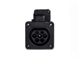
The vehicle coupler is composed of the vehicle connector, which is mounted at the end of a flexible cable, and the vehicle inlet, the counterpart of the connector, which is located within the vehicle. The CCS-couplers are originally based on the Type 1 coupler, the North American Standard, and Type 2 coupler, the European standard, as described in (IEC 62196-2). One of the challenges of the Combined Charging System was to develop a vehicle inlet which is compatible with both the existing AC vehicle connectors and additional DC contacts. For both Type 1 and Type 2 this has been accomplished by extending the inlet by two additional DC contacts below the existing AC and communication contacts. The resulting new configurations are commonly known as Combo 1 and Combo 2. For the DC vehicle connector the implementation varies slightly between Combo 1 and Combo 2. In case of Combo 1 the connector is extended by two DC contacts, while the Type 1 portion of the connector remains the same with the AC contacts (L1 & N) being unused. In case of Combo 2 the AC contacts (here L1, L2, L3 & N) are completely removed from the connector. Consequently the Type 2 portion of the connector has only three contacts remaining, of which two are communication contacts and one is protective earth. In both cases communication and protective earth functions are covered by the original Type 1 or 2 portion of the connector. The Type 1 and Type 2 connector are described in IEC 62196-2, while the Combo 1 and Combo 2 connectors are described in IEC 62196-3 as Configurations EE and FF.
| Inlet\Connector | TYPE 1
 |
COMBO 1
 |
|---|---|---|
 |
||
 |
| Inlet\Connector | TYPE 2
|
COMBO 2
|
|---|---|---|
 |
Single Phase or Three Phase |
|
 |
Single Phase or Three Phase |


High Power Charging
As vehicle couplers for DC charging according to IEC 62196-3:2014 Ed.1 allow DC charging only with currents up to 200 A they do not sufficiently cover the needs of the future charging infrastructure. Consequently the next edition of the standard will support currents of up to 400 A. Such high currents, however, result in numerous problems. High currents either require large cable cross sections, leading to heavy and stiff cables, or require cooling, if thinner cable cross sections are desired. As well the contact resistance leads to more heat dissipation. To cope with these technical issues, the IEC TS 62196-3-1 is currently under development, which describes the requirements for high power DC couplers including thermal sensing, cooling and silver plating of contacts.
Global acceptance
The Combined Charging System is primarily driven by European and North American car manufacturers. Type 1 and Combo 1 charges are primarily found in North and Central America, Korea and Taiwan, while Type 2 and Combo2 can be found in South America, Europe, South Africa, Arabia, India, Oceania and Australia. For DC charging the competing standard GB/T is used in China, while Japan uses CHAdeMO. In many remaining countries no standard is preferred yet, however, a recommendation by CharIN is given to use Type 2 and Combo 2. In the European Union according to the Directive 2014/94/EU[26] all high power DC charging points set up after November 18, 2017 shall be equipped for interoperability purposes at least with Combo 2 connectors. However, this does not prohibit the set-up of other charging points using e.g. CHAdeMO or Tesla Superchargers.
References
- ↑ "Tesla Model 3 could set the charging standard for electric vehicles". Electrek. Retrieved 18 July 2017.
- ↑ "IONIQ Electric - Complete Hyundai Walkthrough Videos On Its 110 Mile EV".
- ↑ "DC fast-charging in east, west coast corridors done, say VW, BMW".
- ↑ "ACEA position and recommendations for the standardization of the charging of electrically chargeable vehicles" (PDF). ACEA – European Automobile Manufacturers Association. 2011-03-02. Archived from the original (PDF) on 2012-12-02.
- ↑ "Universal charging for electric cars". Auto123.com. 2011-11-15.
- ↑ "Seven Auto Manufacturers Collaborate on Harmonized Electric Vehicle Fast Charging Solution". Ford. Retrieved 2012-04-09. |
- ↑ "Weltweit tätige Automobilhersteller zeigen Schnellladen an Elektrofahrzeugen auf der EVS26". Volkswagen AG. 2012-05-03. Retrieved 2012-05-08.
- ↑ "Solutions for E-Mobility" (PDF). Phoenix Contact. 2013. Retrieved 2015-10-08.
- ↑ "Seven Automakers Agree On Combined EV Charging System". 2011-10-12. Retrieved 2012-04-09.
- 1 2 "E-Mobility "Two In One"". EuE24. April 2012. Interview with Phoenix Contact. Retrieved 2012-04-09.
- ↑ "Combined Charging: das universelle Ladesystem für Elektrofahrzeuge wird erstmals an Fahrzeugen deutscher Hersteller gezeigt". BMW Group. 2011-10-11. Retrieved 2012-04-09.
- ↑ "BMW, Daimler and VW Propose Global e-mobility Standardization on Vehicle2Grid Communication, Harmonization of Chargers". 2009-09-26. Retrieved 2012-04-09.
- ↑ "Erste öffentliche 50 KW DC Schnellladesäule auf der e-Mobility-Station in Wolfsburg eingeweiht". Landesinitiative Elektromobilität Niedersachsen. 2013-06-20. Retrieved 2013-07-09.
- ↑ "Schnellladestation an der BMW Welt eröffnet". BMW Group. 2013-07-04. press release. Retrieved 2013-07-09.
- ↑ "2013 World EV Summint in Norway – Chademo, Nissan and Volkswagen align on promoting multi-standard fast chargs to accelerate infrastructure deployment and EV adoption" (PDF). Chademo Association Europe. 2013-06-11. Retrieved 2013-07-09.
- ↑ "CharIN e. V. demonstrates the next level of electric vehicle fast charging" (PDF). 2015-10-14. Retrieved 2015-12-14.
- ↑ "Volvo Cars ger en känga åt Tesla".
- ↑ "CharIN e. V. welcomes member Tesla Motors". 2016-11-09.
- ↑ "CharIN e. V. welcomes Atieva Inc". 2016-11-09.
- ↑ "Toyota Motor Europe joins CharIN e.V." CharIN. Retrieved 31 March 2017.
- ↑ "Volkswagen Dieselgate Settlement Includes $2 Billion Investment Towards Electric Cars".
- ↑ "Our Plan". electrify america. Retrieved 16 July 2018.
- ↑ "5 major automakers join forces to deploy 400 ultra-fast (350 kW) charging stations for electric vehicles in Europe". Electrek. 2016-11-29. Retrieved 2016-11-29.
- ↑ "Carmakers plan 400 Europe car charging stations by 2020". Reuters. 2017-03-11. Retrieved 2018-05-04.
- ↑ "CCS Specification". www.charinev.org. 2017-09-26. Retrieved 2017-11-17.
- ↑ "Directive 2014/94/EU of the European Parliament and of the Council of 22 October 2014 on the deployment of alternative fuels infrastructure Text with EEA relevance, CELEX1". publications.europa.eu. Council of the European Union, European Parliament. 2014-10-22. Retrieved 2018-07-16.
External links
- Charging Interface Initiative (CharIN)