Precipitation hardening
Precipitation hardening, also called age hardening or particle hardening, is a heat treatment technique used to increase the yield strength of malleable materials, including most structural alloys of aluminium, magnesium, nickel, titanium, and some steels and stainless steels. In superalloys, it is known to cause yield strength anomaly providing excellent high-temperature strength. Precipitation hardening relies on changes in solid solubility with temperature to produce fine particles of an impurity phase, which impede the movement of dislocations, or defects in a crystal's lattice. Since dislocations are often the dominant carriers of plasticity, this serves to harden the material. The impurities play the same role as the particle substances in particle-reinforced composite materials. Just as the formation of ice in air can produce sleet, snow, or hail, depending upon the thermal history of a given portion of the atmosphere, precipitation in solids can produce many different sizes of particles, which have radically different properties. Unlike ordinary tempering, alloys must be kept at elevated temperature for hours to allow precipitation to take place. This time delay is called "aging". Solution treatment and aging is sometimes abbreviated "STA" in metals specs and certs.
Note that two different heat treatments involving precipitates can alter the strength of a material: solution heat treating and precipitation heat treating. Solid solution strengthening involves formation of a single-phase solid solution via quenching. Precipitation heat treating involves the addition of impurity particles to increase a material's strength.[1] Precipitation hardening via precipitation heat treatment is the main topic of discussion in this article.
Kinetics versus thermodynamics
This technique exploits the phenomenon of supersaturation, and involves careful balancing of the driving force for precipitation and the thermal activation energy available for both desirable and undesirable processes.
Nucleation occurs at a relatively high temperature (often just below the solubility limit) so that the kinetic barrier of surface energy can be more easily overcome and the maximum number of precipitate particles can form. These particles are then allowed to grow at lower temperature in a process called ageing. This is carried out under conditions of low solubility so that thermodynamics drive a greater total volume of precipitate formation.
Diffusion's exponential dependence upon temperature makes precipitation strengthening, like all heat treatments, a fairly delicate process. Too little diffusion (under ageing), and the particles will be too small to impede dislocations effectively; too much (over ageing), and they will be too large and dispersed to interact with the majority of dislocations.
Alloy design
Precipitation strengthening is possible if the line of solid solubility slopes strongly toward the centre of a phase diagram. While a large volume of precipitate particles is desirable, a small enough amount of the alloying element should be added that it remains easily soluble at some reasonable annealing temperature.
Elements used for precipitation strengthening in typical aluminium and titanium alloys make up about 10% of their composition. While binary alloys are more easily understood as an academic exercise, commercial alloys often use three components for precipitation strengthening, in compositions such as Al(Mg, Cu) and Ti(Al, V). A large number of other constituents may be unintentional, but benign, or may be added for other purposes such as grain refinement or corrosion resistance. In some cases, such as many aluminium alloys, an increase in strength is achieved at the expense of corrosion resistance.
The addition of large amounts of nickel and chromium needed for corrosion resistance in stainless steels means that traditional hardening and tempering methods are not effective. However, precipitates of chromium, copper, or other elements can strengthen the steel by similar amounts in comparison to hardening and tempering. The strength can be tailored by adjusting the annealing process, with lower initial temperatures resulting in higher strengths. The lower initial temperatures increase the driving force of nucleation. More driving force means more nucleation sites, and more sites means more places for dislocations to be disrupted while the finished part is in use.
Many alloy systems allow the ageing temperature to be adjusted. For instance, some aluminium alloys used to make rivets for aircraft construction are kept in dry ice from their initial heat treatment until they are installed in the structure. After this type of rivet is deformed into its final shape, ageing occurs at room temperature and increases its strength, locking the structure together. Higher ageing temperatures would risk over-ageing other parts of the structure, and require expensive post-assembly heat treatment because a high ageing temperature promotes the precipitate to grow too readily.
Types of hardening
There are several ways by which a matrix can be hardened by precipitates, which could also be different for deforming precipitates and non-deforming precipitates.[2]
Deforming particles:
Coherency hardening occurs when the interface between the particles and the matrix is coherent, depending on parameters like particle size, the way that particles are introduced by. Small particles precipitated from supersaturated solid solution usually have coherent interfaces with the matrix. Coherency hardening originates from atomic volume difference between precipitate and the matrix, which results in a coherency strain. The associated stress field interacts with dislocations leading to an increase in yield strength, similar to the size effect in solid solution strengthening.
Modulus hardening results from different shear modulus of the precipitate and the matrix, which leads to an energy change of dislocation line tension when the dislocation line cuts the precipitate. Besides, the dislocation line could bend when entering the precipitate, increasing the affected length of the dislocation line.
Chemical strengthening is associated with the surface energy of newly introduced precipitate-matrix interface when the particle is sheared by dislocations. Similar as modulus hardening, the analysis of interfacial area can be complicated by dislocation line distortion.
Order strengthening occurs when the precipitate is ordered structure such that bond energy before and after shearing is different. For example, in an ordered cubic crystal with composition AB, bond energy of A-A and B-B after shearing is higher than that of A-B bond before. The associated energy increase per unit area is anti-phase boundary energy and accumulates gradually as the dislocation passes through the particle. However, a second dislocation could remove the anti-phase domain left by the first dislocation when traverses the particle. The attraction of the particle and the repulsion of the first dislocation maintains a balanced distance between two dislocations, which makes order strengthening more complicated.
Non-deforming particles:
In non-deforming particles, where the spacing is small enough or the precipitate-matrix interface is disordered, dislocation bows instead of shears. The strengthening is related to the effective spacing between particles considering finite particle size, but not particle strength, because once the particle is strong enough for the dislocations to bow rather than cut, further increase of the dislocation penetration resistance won't affect strengthening.
Theory
The primary species of precipitation strengthening are second phase particles. These particles impede the movement of dislocations throughout the lattice. You can determine whether or not second phase particles will precipitate into solution from the solidus line on the phase diagram for the particles. Physically, this strengthening effect can be attributed both to size and modulus effects, and to interfacial or surface energy.[2][3]
The presence of second phase particles often causes lattice distortions. These lattice distortions result when the precipitate particles differ in size and crystallographic structure from the host atoms. Smaller precipitate particles in a host lattice leads to a tensile stress, whereas larger precipitate particles leads to a compressive stress. Dislocation defects also create a stress field. Above the dislocation there is a compressive stress and below there is a tensile stress. Consequently, there is a negative interaction energy between a dislocation and a precipitate that each respectively cause a compressive and a tensile stress or vice versa. In other words, the dislocation will be attracted to the precipitate. In addition, there is a positive interaction energy between a dislocation and a precipitate that have the same type of stress field. This means that the dislocation will be repulsed by the precipitate.
Precipitate particles also serve by locally changing the stiffness of a material. Dislocations are repulsed by regions of higher stiffness. Conversely, if the precipitate causes the material to be locally more compliant, then the dislocation will be attracted to that region. In addition, there are three types of interphase boundaries (IPBs).
The first type is a coherent or ordered IPB, the atoms match up one by one along the boundary. Due to difference in lattice parameters of the two phases, a coherency strain energy is associated with this type of boundary. The second type is a fully disordered IPB and there are no coherency strains, but the particle tends to be non-deforming to dislocations. The last one is a partially ordered IPB, so coherency strains are partially relieved by the periodic introduction of dislocations along the boundary.
In coherent precipitates in a matrix, if the precipitate has a lattice parameter less than that of the matrix, then the atomic match across the IPB leads to an internal stress field that interacts with moving dislocations.
There are two deformation paths, one is the coherency hardening, the lattice mismatch is


Where is the shear modulus, is the coherent lattice mismatch, is the particle radius, is the particle volume fraction, is the burgers vector, equals the concentration.


The other one is modulus hardening. The energy of the dislocation energy is , when it cuts through the precipitate, its energy is , the change in line segment energy is


.

The maximum dislocation length affected is the particle diameter, the line tension change takes place gradually over a distance equal to . The interaction force between the dislocation and the precipitate is
and .


Furthermore, a dislocation may cut through a precipitate particle, and introduce more precipitate-matrix interface, which is chemical strengthening. When the dislocation is entering the particle and is within the particle, the upper part of the particle shears b with respect to the lower part accompanies the dislocation entry. A similar process occurs when the dislocation exits the particle. The complete transit is accompanied by creation of matrix-precipitate surface area of approximate magnitude , where r is the radius of the particle and b is the magnitude of the burgers vector. The resulting increase in surface energy is , where is the surface energy. The maximum force between the dislocation and particle is , the corresponding flow stress should be .


When a particle is sheared by a dislocation, a threshold shear stress is needed to deform the particle. The expression for the required shear stress is as follows:

When the precipitate size is small, the required shear stress is proportional to the precipitate size , However, for a fixed particle volume fraction, this stress may decrease at larger values of r owing to an increase in particle spacing. The overall level of the curve is raised by increases in either inherent particle strength or particle volume fraction.


The dislocation can also bow around a precipitate particle through so-called Orowan mechanism.
Since the particle is non-deforming, the dislocation bows around the particles ( ), the stress required to effect the bypassing is inversely proportional to the interparticle spacing , that is, , where is the particle radius. Dislocation loops encircle the particles after the bypass operation, a subsequent dislocation would have to be extruded between the loops. Thus, the effective particle spacing for the second dislocation is reduced to with , and the bypassing stress for this dislocation should be , which is greater than for the first one. However, as the radius of particle increases, will increase so as to maintain the same volume fraction of precipitates, will increase and will decrease. As a result, the material will become weaker as the precipitate size increases.


For a fixed particle volume fraction, decreases with increasing r as this is accompanied by an increase in particle spacing.
On the other hand, increasing increases the level of the stress as a result of a finer particle spacing. The level of is unaffected by particle strength. That is, once a particle is strong enough to resist cutting, any further increase in its resistance to dislocation penetration has no effect on , which depends only on matrix properties and effective particle spacing.
If particles of A of volume fraction are dispersed in a matrix, particles are sheared for and are bypassed for , maximum strength is obtained at , where the cutting and bowing stresses are equal. If inherently harder particles of B of the same volume fraction are present, the level of the curve is increased but that of the one is not. Maximum hardening, greater than that for A particles, is found at . Increasing the volume fraction of A raises the level of both and and increases the maximum strength obtained. The latter is found at , which may be either less than or greater than depending on the shape of the curve.


Governing equations
There are two main types of equations to describe the two mechanisms for precipitation hardening:
Dislocation cutting through particles: For most strengthening at the early stage, it increases with , where is a dimensionless mismatch parameter (for example, in coherency hardening, is the fractional change of precipitate and matrix lattice parameter), is the volume fraction of precipitate, is the precipitate radius, and is the magnitude of the Burgers vector. According to this relationship, materials strength increases with increasing mismatch, volume fraction, and particle size, so that dislocation is easier to cut through particles with smaller radius.


For different types of hardening through cutting, governing equations are as following. For coherency hardening, , , where is increased shear stress, is the shear modulus of the matrix, and are the lattice parameter of the precipitate or the matrix.


For modulus hardening, , , where and are the shear modulus of the precipitate or the matrix.


For chemical strengthening, , , where is the particle-matrix interphase surface energy.


For order strengthening, (low , early stage precipitation), where the dislocations are widely separated; (high , early stage precipitation), where the dislocations are not widely separated; , where is anti-phase boundary energy.


Dislocations bowing around particles: When the precipitate is strong enough to resist dislocation penetration, dislocation bows and the maximum stress is given by Orowan equation. Dislocation bowing, also called Orowan strengthening,[4] is more likely to occur when the particle density in the material is lower.

where is the material strength, is the shear modulus, is the magnitude of the Burgers vector, is the distance between pinning points, and is the second phase particle radius. This governing equation shows that for dislocation bowing the strength is inversely proportional to the second phase particle radius , because when the volume fraction of the precipitate is fixed, the spacing between particles increases concurrently with the particle radius , therefore increases with .

These governing equations show that the precipitation hardening mechanism depends on the size of the precipitate particles. At small , cutting will dominate, while at large , bowing will dominate.
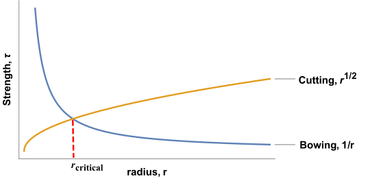
Looking at the plot of both equations, it is clear that there is a critical radius at which max strengthening occurs. This critical radius is typically 5-30 nm.
Examples of precipitation hardening materials
- 2000-series aluminium alloys (important examples: 2024 and 2019, also Y alloy and Hiduminium)
- 6000-series aluminium alloys (important example: 6061 for bicycle frames and aeronautical structures)
- 7000-series aluminium alloys (important examples: 7075 and 7475)
- 17-4 stainless steel (UNS S17400)
- Maraging steel
- Inconel 718
- Alloy X-750
- René 41
- Waspaloy
- Copper Precipitation-Hardened Steels
- Mulberry (uranium alloy)
See also
References
- ↑ W.D. Callister. Fundamentals of Materials Science and Engineering, 2nd ed. Wiley & Sons. pp. 252.
- 1 2 Thosmas H. Courtney. Mechanical Behavior of Materials, 2nd ed. Waveland Press, Inc.. pp. 198-205.
- ↑ T. Gladman, Precipitatipn hardening in metals.
- ↑ Orowan Bowing Archived 2011-09-28 at the Wayback Machine.
Further reading
- ASM metals handbook vol 4 heat treating
External links
| Iron production (Ironworks) |
|  | |||||||
|---|---|---|---|---|---|---|---|---|---|
| Steelmaking (Steel mill) |
| ||||||||
| Production by country | |||||||||
| Heat treatment methods |
| ||||||||