USB
Universal Serial Bus (USB) is an industry standard that establishes specifications for cables and connectors and protocols for connection, communication and power supply (interfacing) between computers, peripherals and other computers.[3] Released in 1996, the USB standard is currently maintained by the USB Implementers Forum (USB-IF). There have been four generations of USB specifications: USB 1.x, USB 2.0, USB 3.x and USB4.[4]
 The certified USB logo | |||
| Type | Bus | ||
|---|---|---|---|
| Production history | |||
| Designer | Compaq, DEC, IBM, Intel, Microsoft, NEC, and Nortel | ||
| Designed | January 1996 | ||
| Produced | Since May 1996[1] | ||
| Superseded | Serial port, parallel port, game port, Apple Desktop Bus, PS/2 port, and FireWire (IEEE 1394) | ||
| General specifications | |||
| Length | 2–5 m (6 ft 7 in–16 ft 5 in) (by category) | ||
| Width |
| ||
| Height |
| ||
| Hot pluggable | Yes | ||
| External | Yes | ||
| Cable |
| ||
| Pins |
| ||
| Connector | Unique | ||
| Electrical | |||
| Signal | 5 V DC | ||
| Max. voltage |
| ||
| Max. current |
| ||
| Data | |||
| Data signal | Packet data, defined by specifications | ||
| Width | 1 bit | ||
| Bitrate | 1.5; 12; 480; 5,000; 10,000; 20,000 Mbit/s (depending on mode) | ||
| Max. devices | 127 | ||
| Protocol | Serial | ||
| Pin out | |||
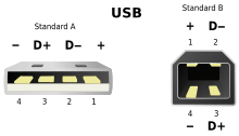 | |||
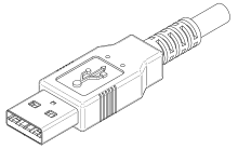
| The USB-A plug (left) and USB-B plug (right) | |||
| Pin 1 | VBUS (+5 V) | ||
| Pin 2 | Data− | ||
| Pin 3 | Data+ | ||
| Pin 4 | Ground | ||
Overview
USB was designed to standardize the connection of peripherals to personal computers, both to communicate with and to supply electric power. It has largely replaced interfaces such as serial ports and parallel ports, and has become commonplace on a wide range of devices. Examples of peripherals that are connected via USB include computer keyboards and mice, video cameras, printers, portable media players, disk drives and network adapters.
USB connectors have been increasingly replacing other types as charging cables of portable devices.
Receptacle (socket) identification
This section is intended to allow fast identification of USB receptacles (sockets) on equipment. Further diagrams and discussion of plugs and receptacles can be found in the main article above.
| Connectors | USB 1.0 1996 |
USB 2.0 2001 |
USB 2.0 Revised |
USB 3.0 2011 |
USB 3.1 2014 |
USB 3.2 2017 |
USB4 2019 | |
|---|---|---|---|---|---|---|---|---|
| Data rate | 1.5 Mbit/s (Low Speed) |
1.5 Mbit/s
(Low Speed) 12 Mbit/s (Full Speed) 480 Mbit/s |
5 Gbit/s (SuperSpeed) |
10 Gbit/s (SuperSpeed+) |
20 Gbit/s (SuperSpeed+) |
40 Gbit/s (SuperSpeed+ and Thunderbolt 3) | ||
| 12 Mbit/s (Full Speed) | ||||||||
| Standard | A | Type A |
Type A |
Deprecated | ||||
| B | Type B |
Type B |
Deprecated | |||||
| C | N/A | Type C (enlarged) | ||||||
| Mini | A | N/A | Mini A |
Deprecated | ||||
| B | Mini B | |||||||
| AB | N/A | Mini AB | ||||||
| Micro | A | N/A | ||||||
| B | N/A | Micro B |
Micro B |
Deprecated | ||||
| AB | Micro AB |
Deprecated | ||||||
| Connectors | USB 1.0 1996 |
USB 2.0 2001 |
USB 2.0 Revised |
USB 3.0 2011 |
USB 3.1 2014 |
USB 3.2 2017 |
USB4 2019 | |
Objectives
The Universal Serial Bus was developed to simplify and improve the interface between personal computers and peripheral devices, when compared with previously existing standard or ad-hoc proprietary interfaces.[5]
From the computer user's perspective, the USB interface improves ease of use in several ways:
- The USB interface is self-configuring, eliminating the need for the user to adjust the device's settings for speed or data format, or configure interrupts, input/output addresses, or direct memory access channels.[6]
- USB connectors are standardized at the host, so any peripheral can use most available receptacles.
- USB takes full advantage of the additional processing power that can be economically put into peripheral devices so that they can manage themselves. As such, USB devices often do not have user-adjustable interface settings.
- The USB interface is hot-swappable (devices can be exchanged without rebooting the host computer).
- Small devices can be powered directly from the USB interface, eliminating the need for additional power supply cables.
- Because use of the USB logo is only permitted after compliance testing, the user can have confidence that a USB device will work as expected without extensive interaction with settings and configuration.
- The USB interface defines protocols for recovery from common errors, improving reliability over previous interfaces.[5]
- Installing a device that relies on the USB standard requires minimal operator action. When a user plugs a device into a port on a running computer, it either entirely automatically configures using existing device drivers, or the system prompts the user to locate a driver, which it then installs and configures automatically.
The USB standard also provides multiple benefits for hardware manufacturers and software developers, specifically in the relative ease of implementation:
- The USB standard eliminates the requirement to develop proprietary interfaces to new peripherals.
- The wide range of transfer speeds available from a USB interface suits devices ranging from keyboards and mice up to streaming video interfaces.
- A USB interface can be designed to provide the best available latency for time-critical functions, or can be set up to do background transfers of bulk data with little impact on system resources.
- The USB interface is generalized with no signal lines dedicated to only one function of one device.[5]
Limitations
As with all standards, USB possesses multiple limitations to its design:
- USB cables are limited in length, as the standard was intended for peripherals on the same table-top, not between rooms or buildings. However, a USB port can be connected to a gateway that accesses distant devices.
- USB has a strict tree network topology and master/slave protocol for addressing peripheral devices; those devices cannot interact with one another except via the host, and two hosts cannot communicate over their USB ports directly. Some extension to this limitation is possible through USB On-The-Go.
- A host cannot broadcast signals to all peripherals at once—each must be addressed individually. Some very high speed peripheral devices require sustained speeds not available in the USB standard.[5]
- While converters exist between certain legacy interfaces and USB, they may not provide full implementation of the legacy hardware. For example, a USB-to-parallel-port converter may work well with a printer, but not with a scanner that requires bi-directional use of the data pins.
For a product developer, using USB requires implementation of a complex protocol and implies an "intelligent" controller in the peripheral device. Developers of USB devices intended for public sale generally must obtain a USB ID, which requires that they pay a fee to the USB Implementers Forum. Developers of products that use the USB specification must sign an agreement with the Implementers Forum. Use of the USB logos on the product require annual fees and membership in the organization.[5]
History
A group of seven companies began the development of USB in 1994: Compaq, DEC, IBM, Intel, Microsoft, NEC, and Nortel.[8] The goal was to make it fundamentally easier to connect external devices to PCs by replacing the multitude of connectors at the back of PCs, addressing the usability issues of existing interfaces, and simplifying software configuration of all devices connected to USB, as well as permitting greater data rates for external devices. Ajay Bhatt and his team worked on the standard at Intel;[9][10] the first integrated circuits supporting USB were produced by Intel in 1995.[11]
The original USB 1.0 specification, which was introduced in January 1996, defined data transfer rates of 1.5 Mbit/s Low Speed and 12 Mbit/s Full Speed.[11] Draft designs had called for a single-speed 5 Mbit/s bus, but the low speed was added to support low-cost peripherals with unshielded cables,[12] resulting in a split design with a 12 Mbit/s data rate was intended for higher-speed devices such as printers and floppy disk drives, and the lower 1.5 Mbit/s rate for low data rate devices such as keyboards, mice and joysticks.[13] Microsoft Windows 95, OSR 2.1 provided OEM support for the devices in August 1997. The first widely used version of USB was 1.1, which was released in September 1998. Apple Inc.'s iMac was the first mainstream product with USB and the iMac's success popularized USB itself.[14] Following Apple's design decision to remove all legacy ports from the iMac, many PC manufacturers began building legacy-free PCs, which led to the broader PC market using USB as a standard.[15][16][17]
The USB 2.0 specification was released in April 2000 and was ratified by the USB Implementers Forum (USB-IF) at the end of 2001. Hewlett-Packard, Intel, Lucent Technologies (now Nokia), NEC, and Philips jointly led the initiative to develop a higher data transfer rate, with the resulting specification achieving 480 Mbit/s, 40 times as fast as the original USB 1.1 specification.
The USB 3.0 specification was published on 12 November 2008. Its main goals were to increase the data transfer rate (up to 5 Gbit/s), decrease power consumption, increase power output, and be backward compatible with USB 2.0.[18](3–1) USB 3.0 includes a new, higher speed bus called SuperSpeed in parallel with the USB 2.0 bus.[18](1–3) For this reason, the new version is also called SuperSpeed.[19] The first USB 3.0 equipped devices were presented in January 2010.[19][20]
As of 2008, approximately 6 billion USB ports and interfaces were in the global marketplace, and about 2 billion were being sold each year.[21]
The USB 3.1 specification was published in July 2013.
In December 2014, USB-IF submitted USB 3.1, USB Power Delivery 2.0 and USB-C specifications to the IEC (TC 100 – Audio, video and multimedia systems and equipment) for inclusion in the international standard IEC 62680 (Universal Serial Bus interfaces for data and power), which is currently based on USB 2.0.[22]
The USB 3.2 specification was published in September 2017.
USB 1.x
Released in January 1996, USB 1.0 specified data rates of 1.5 Mbit/s (Low Bandwidth or Low Speed) and 12 Mbit/s (Full Speed).[23] It did not allow for extension cables or pass-through monitors, due to timing and power limitations. Few USB devices made it to the market until USB 1.1 was released in August 1998. USB 1.1 was the earliest revision that was widely adopted and led to what Microsoft designated the "Legacy-free PC".[14][16][17]
Neither USB 1.0 nor 1.1 specified a design for any connector smaller than the standard type A or type B. Though many designs for a miniaturised type B connector appeared on many peripherals, conformity to the USB 1.x standard was hampered by treating peripherals that had miniature connectors as though they had a tethered connection (that is: no plug or receptacle at the peripheral end). There was no known miniature type A connector until USB 2.0 (revision 1.01) introduced one.
USB 2.0

USB 2.0 was released in April 2000, adding a higher maximum signaling rate of 480 Mbit/s (60 MB/s) named High Speed or High Bandwidth, in addition to the USB 1.x Full Speed signaling rate of 12 Mbit/s.
Modifications to the USB specification have been made via Engineering Change Notices (ECN). The most important of these ECNs are included into the USB 2.0 specification package available from USB.org:[24]
- Mini-A and Mini-B Connector
- Micro-USB Cables and Connectors Specification 1.01
- InterChip USB Supplement
- On-The-Go Supplement 1.3 USB On-The-Go makes it possible for two USB devices to communicate with each other without requiring a separate USB host
- Battery Charging Specification 1.1 Added support for dedicated chargers, host chargers behavior for devices with dead batteries
- Battery Charging Specification 1.2:[25] with increased current of 1.5 A on charging ports for unconfigured devices, allowing High Speed communication while having a current up to 1.5 A and allowing a maximum current of 5 A
- Link Power Management Addendum ECN, which adds a sleep power state
USB 3.x

The USB 3.0 specification was released on 12 November 2008, with its management transferring from USB 3.0 Promoter Group to the USB Implementers Forum (USB-IF), and announced on 17 November 2008 at the SuperSpeed USB Developers Conference.[26]
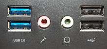
USB 3.0 adds a SuperSpeed transfer mode, with associated backward compatible plugs, receptacles, and cables. SuperSpeed plugs and receptacles are identified with a distinct logo and blue inserts in standard format receptacles.
The SuperSpeed bus provides for a transfer mode at a nominal rate of 5.0 Gbit/s, in addition to the three existing transfer modes. Its efficiency is dependent on a number of factors including physical symbol encoding and link level overhead. At a 5 Gbit/s signaling rate with 8b/10b encoding, each byte needs 10 bits to transmit, so the raw throughput is 500 MB/s. When flow control, packet framing and protocol overhead are considered, it is realistic for 400 MB/s (3.2 Gbit/s) or more to transmit to an application.[18](4–19) Communication is full-duplex in SuperSpeed transfer mode; earlier modes are half-duplex, arbitrated by the host.[27]
Low-power and high-power devices remain operational with this standard, but devices using SuperSpeed can take advantage of increased available current of between 150 mA and 900 mA, respectively.[18](9–9)
USB 3.1, released in July 2013 has two variants. The first one preserves USB 3.0's SuperSpeed transfer mode and is labeled USB 3.1 Gen 1,[28][29] and the second version introduces a new SuperSpeed+ transfer mode under the label of USB 3.1 Gen 2. SuperSpeed+ doubles the maximum data signaling rate to 10 Gbit/s, while reducing line encoding overhead to just 3% by changing the encoding scheme to 128b/132b.[28][30]
USB 3.2, released in September 2017,[31] preserves existing USB 3.1 SuperSpeed and SuperSpeed+ data modes but introduces two new SuperSpeed+ transfer modes over the USB-C connector with data rates of 10 and 20 Gbit/s (1.25 and 2.5 GB/s). The increase in bandwidth is a result of multi-lane operation over existing wires that were intended for flip-flop capabilities of the USB-C connector.[32]
USB 3.0 also introduced the UASP protocol, which provides generally faster transfer speeds than the BOT (Bulk-Only-Transfer) protocol.
Current naming scheme
Starting with the USB 3.2 standard, USB-IF introduced a new naming scheme.[33]. To help companies with branding of the different transfer modes, USB-IF recommended branding the 5, 10, and 20 Gbit/s transfer modes as SuperSpeed USB 5Gbps, SuperSpeed USB 10Gbps, and SuperSpeed USB 20Gbps, respectively:[34]
| Name | Old name | Original name | USB-IF branding | Transfer speed |
|---|---|---|---|---|
| USB 3.2 Gen 1 | USB 3.1 Gen 1 | USB 3.0 | SuperSpeed USB 5Gbps | 5 Gbit/s |
| USB 3.2 Gen 2 | USB 3.1 Gen 2 | USB 3.1 | SuperSpeed USB 10Gbps | 10 Gbit/s |
| USB 3.2 Gen 2 x 2 | USB 3.2 | SuperSpeed USB 20Gbps | 20 Gbit/s |
USB4
The USB4 specification was released on 29 August 2019 by USB Implementers Forum.[35]
USB4 is based on the Thunderbolt 3 protocol specification.[36] It supports 40 Gbit/s throughput, is compatible with Thunderbolt 3, and backwards compatible with USB 3.2 and USB 2.0.[37][38] The architecture defines a method to share a single high-speed link with multiple end device types dynamically that best serves the transfer of data by type and application.
The USB4 specification states that the following technologies shall be supported by USB4:[39]
| Connection | Mandatory for | Remarks | ||
|---|---|---|---|---|
| host | hub | device | ||
| USB 2.0 (480 Mbit/s) | Yes | Yes | Yes | Contrary to other functions—which use the multiplexing of high-speed links—USB 2.0 over USB-C utilises its own differential pair of wires. |
| USB Gen 2x2 (20 Gbit/s) | Yes | Yes | Yes | A USB 3.0-labelled device still operates via a USB4 host or hub as a USB 3.0 device. The device requirement of Gen 2x2 applies only to the newcoming USB4-labelled devices. |
| USB Gen 3x2 (40 Gbit/s) | No | Yes | No | |
| DisplayPort | Yes | Yes | No | The specification requires that hosts and hubs support the DisplayPort Alternate Mode. |
| Host-to-Host communications | Yes | Yes | N/A | A LAN-like connection between two peers. |
| PCI Express | No | Yes | No | The PCI Express function of USB4 replicates the functionality of previous versions of the Thunderbolt specification. |
| Thunderbolt 3 | No | Yes | No | Thunderbolt 3 uses USB-C cables; the USB4 specification allows hosts and devices and requires hubs to support interoperability with the standard using the Thunderbolt 3 Alternate Mode. |
| Other Alternate Modes | No | No | No | USB4 products may optionally offer interoperability with the HDMI, MHL, and VirtualLink Alternate Modes. |
During CES 2020, USB-IF and Intel stated their intention to allow USB4 products that support all the optional functionality as Thunderbolt 4 products. The first products compatible with USB4 are expected to be Intel's Tiger Lake series and AMD's Zen 3 series of CPUs, due for release in late 2020.
Version history
Release versions
| Name | Release date | Maximum transfer rate | Note |
|---|---|---|---|
| USB 0.7 | 11 November 1994 | ? | Pre-release |
| USB 0.8 | December 1994 | ? | Pre-release |
| USB 0.9 | 13 April 1995 | Full Speed (12 Mbit/s) | Pre-release |
| USB 0.99 | August 1995 | ? | Pre-release |
| USB 1.0-RC | November 1995 | ? | Release Candidate |
| USB 1.0 | 15 January 1996 | Full Speed (12 Mbit/s),
Low Speed (1.5 Mbit/s) |
|
| USB 1.1 | August 1998 | ||
| USB 2.0 | April 2000 | High Speed (480 Mbit/s) | |
| USB 3.0 | November 2008 | Superspeed USB (5 Gbit/s) | Also referred to as USB 3.1 Gen 1[28] and USB 3.2 Gen 1 × 1 |
| USB 3.1 | July 2013 | Superspeed+ USB (10 Gbit/s) | Includes new USB 3.1 Gen 2,[28] also named USB 3.2 Gen 2 × 1 in later specifications |
| USB 3.2 | August 2017 | Superspeed+ USB dual-lane (20 Gbit/s) | Includes new Gen 1 × 2 and Gen 2 × 2 multi-link modes[40] |
| USB4 | August 2019 | 40 Gbit/s (2-lane) | Includes new Gen 3 × 1 and Gen 3 × 2 modes and introduces USB4 routing for tunnelling of USB3.x, DisplayPort 1.4a and PCI Express traffic and host-to-host transfers, based on the Thunderbolt 3 protocol |
Power-related specifications
| Release name | Release date | Max. power | Note |
|---|---|---|---|
| USB Battery Charging 1.0 | 2007-03-08 | 5 V, ? A | |
| USB Battery Charging 1.1 | 2009-04-15 | 5 V, 1.8 A | [41] |
| USB Battery Charging 1.2 | 2010-12-07 | 5 V, 5 A | [42] |
| USB Power Delivery revision 1.0 (version 1.0) | 2012-07-05 | 20 V, 5 A | Using FSK protocol over bus power (VBUS) |
| USB Power Delivery revision 1.0 (version 1.3) | 2014-03-11 | 20 V, 5 A | |
| USB Type-C rev1.0 | 2014-08-11 | 5 V, 3 A | New connector and cable specification |
| USB Power Delivery revision 2.0 (version 1.0) | 2014-08-11 | 20 V, 5 A | Using BMC protocol over communication channel (CC) on USB-C cables. |
| USB Type-C rev1.1 | 2015-04-03 | 5 V, 3 A | |
| USB Power Delivery revision 2.0 (version 1.1) | 2015-05-07 | 20 V, 5 A | |
| USB Type-C rev1.2 | 2016-03-25 | 5 V, 3 A | |
| USB Power Delivery revision 2.0 (version 1.2) | 2016-03-25 | 20 V, 5 A | |
| USB Power Delivery revision 2.0 (version 1.3) | 2017-01-12 | 20 V, 5 A | |
| USB Power Delivery revision 3.0 (version 1.1) | 2017-01-12 | 20 V, 5 A | |
| USB Type-C rev1.3 | 2017-07-14 | 5 V, 3 A | |
| USB Power Delivery revision 3.0 (version 1.2) | 2018-06-21 | 20 V, 5 A | |
| USB Type-C rev1.4 | 2019-03-29 | 5 V, 3 A | |
| USB Type-C rev2.0 | 2019-08-29 | 5 V, 3 A | Enabling USB4 over USB Type-C connectors and cables. |
| USB Power Delivery revision 3.0 (version 2.0) | 2019-08-29 | 20 V, 5 A | [43] |
System design
A USB system consists of a host with one or more downstream ports, and multiple peripherals, forming a tiered-star topology. Additional USB hubs may be included, allowing up to five tiers. A USB host may have multiple controllers, each with one or more ports. Up to 127 devices may be connected to a single host controller.[44][18](8–29) USB devices are linked in series through hubs. The hub built into the host controller is called the root hub.
A USB device may consist of several logical sub-devices that are referred to as device functions. A composite device may provide several functions, for example, a webcam (video device function) with a built-in microphone (audio device function). An alternative to this is a compound device, in which the host assigns each logical device a distinct address and all logical devices connect to a built-in hub that connects to the physical USB cable.
.svg.png)
USB device communication is based on pipes (logical channels). A pipe is a connection from the host controller to a logical entity within a device, called an endpoint. Because pipes correspond to endpoints, the terms are sometimes used interchangeably. Each USB device can have up to 32 endpoints (16 in and 16 out), though it is rare to have so many. Endpoints are defined and numbered by the device during initialization (the period after physical connection called "enumeration") and so are relatively permanent, whereas pipes may be opened and closed.
There are two types of pipe: stream and message.
- A message pipe is bi-directional and is used for control transfers. Message pipes are typically used for short, simple commands to the device, and for status responses from the device, used, for example, by the bus control pipe number 0.
- A stream pipe is a uni-directional pipe connected to a uni-directional endpoint that transfers data using an isochronous,[45] interrupt, or bulk transfer:
- Isochronous transfers
- At some guaranteed data rate (for fixed-bandwidth streaming data) but with possible data loss (e.g., realtime audio or video)
- Interrupt transfers
- Devices that need guaranteed quick responses (bounded latency) such as pointing devices, mice, and keyboards
- Bulk transfers
- Large sporadic transfers using all remaining available bandwidth, but with no guarantees on bandwidth or latency (e.g., file transfers)
When a host starts a data transfer, it sends a TOKEN packet containing an endpoint specified with a tuple of (device_address, endpoint_number). If the transfer is from the host to the endpoint, the host sends an OUT packet (a specialization of a TOKEN packet) with the desired device address and endpoint number. If the data transfer is from the device to the host, the host sends an IN packet instead. If the destination endpoint is a uni-directional endpoint whose manufacturer's designated direction does not match the TOKEN packet (e.g. the manufacturer's designated direction is IN while the TOKEN packet is an OUT packet), the TOKEN packet is ignored. Otherwise, it is accepted and the data transaction can start. A bi-directional endpoint, on the other hand, accepts both IN and OUT packets.
Endpoints are grouped into interfaces and each interface is associated with a single device function. An exception to this is endpoint zero, which is used for device configuration and is not associated with any interface. A single device function composed of independently controlled interfaces is called a composite device. A composite device only has a single device address because the host only assigns a device address to a function.
When a USB device is first connected to a USB host, the USB device enumeration process is started. The enumeration starts by sending a reset signal to the USB device. The data rate of the USB device is determined during the reset signaling. After reset, the USB device's information is read by the host and the device is assigned a unique 7-bit address. If the device is supported by the host, the device drivers needed for communicating with the device are loaded and the device is set to a configured state. If the USB host is restarted, the enumeration process is repeated for all connected devices.
The host controller directs traffic flow to devices, so no USB device can transfer any data on the bus without an explicit request from the host controller. In USB 2.0, the host controller polls the bus for traffic, usually in a round-robin fashion. The throughput of each USB port is determined by the slower speed of either the USB port or the USB device connected to the port.
High-speed USB 2.0 hubs contain devices called transaction translators that convert between high-speed USB 2.0 buses and full and low speed buses. There may be one translator per hub or per port.
Because there are two separate controllers in each USB 3.0 host, USB 3.0 devices transmit and receive at USB 3.0 data rates regardless of USB 2.0 or earlier devices connected to that host. Operating data rates for earlier devices are set in the legacy manner.
Device classes
The functionality of a USB device is defined by a class code sent to a USB host. This allows the host to load software modules for the device and to support new devices from different manufacturers.
Device classes include:[46]
| Class | Usage | Description | Examples, or exception |
|---|---|---|---|
| 00h | Device | Unspecified[47] | Device class is unspecified, interface descriptors are used to determine needed drivers |
| 01h | Interface | Audio | Speaker, microphone, sound card, MIDI |
| 02h | Both | Communications and CDC Control | Modem, Ethernet adapter, Wi-Fi adapter, RS-232 serial adapter. Used together with class 0Ah (CDC-Data, below) |
| 03h | Interface | Human interface device (HID) | Keyboard, mouse, joystick |
| 05h | Interface | Physical Interface Device (PID) | Force feedback joystick |
| 06h | Interface | Image (PTP/MTP) | Webcam, scanner |
| 07h | Interface | Printer | Laser printer, inkjet printer, CNC machine |
| 08h | Interface | Mass storage (MSC or UMS) | USB flash drive, memory card reader, digital audio player, digital camera, external drive |
| 09h | Device | USB hub | Full bandwidth hub |
| 0Ah | Interface | CDC-Data | Used together with class 02h (Communications and CDC Control, above) |
| 0Bh | Interface | Smart Card | USB smart card reader |
| 0Dh | Interface | Content security | Fingerprint reader |
| 0Eh | Interface | Video | Webcam |
| 0Fh | Interface | Personal healthcare device class (PHDC) | Pulse monitor (watch) |
| 10h | Interface | Audio/Video (AV) | Webcam, TV |
| 11h | Device | Billboard | Describes USB-C alternate modes supported by device |
| DCh | Both | Diagnostic Device | USB compliance testing device |
| E0h | Interface | Wireless Controller | Bluetooth adapter, Microsoft RNDIS |
| EFh | Both | Miscellaneous | ActiveSync device |
| FEh | Interface | Application-specific | IrDA Bridge, Test & Measurement Class (USBTMC),[48] USB DFU (Device Firmware Upgrade)[49] |
| FFh | Both | Vendor-specific | Indicates that a device needs vendor-specific drivers |
USB mass storage / USB drive
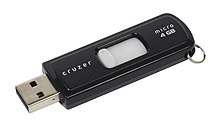
USB mass storage device class (MSC or UMS) standardizes connections to storage devices. At first intended for magnetic and optical drives, it has been extended to support flash drives. It has also been extended to support a wide variety of novel devices as many systems can be controlled with the familiar metaphor of file manipulation within directories. The process of making a novel device look like a familiar device is also known as extension. The ability to boot a write-locked SD card with a USB adapter is particularly advantageous for maintaining the integrity and non-corruptible, pristine state of the booting medium.
Though most personal computers since early 2005 can boot from USB mass storage devices, USB is not intended as a primary bus for a computer's internal storage. However, USB has the advantage of allowing hot-swapping, making it useful for mobile peripherals, including drives of various kinds.
Several manufacturers offer external portable USB hard disk drives, or empty enclosures for disk drives. These offer performance comparable to internal drives, limited by the current number and types of attached USB devices, and by the upper limit of the USB interface. Other competing standards for external drive connectivity include eSATA, ExpressCard, FireWire (IEEE 1394), and most recently Thunderbolt.
Another use for USB mass storage devices is the portable execution of software applications (such as web browsers and VoIP clients) with no need to install them on the host computer.[50][51]
Media Transfer Protocol
Media Transfer Protocol (MTP) was designed by Microsoft to give higher-level access to a device's filesystem than USB mass storage, at the level of files rather than disk blocks. It also has optional DRM features. MTP was designed for use with portable media players, but it has since been adopted as the primary storage access protocol of the Android operating system from the version 4.1 Jelly Bean as well as Windows Phone 8 (Windows Phone 7 devices had used the Zune protocol – an evolution of MTP). The primary reason for this is that MTP does not require exclusive access to the storage device the way UMS does, alleviating potential problems should an Android program request the storage while it is attached to a computer. The main drawback is that MTP is not as well supported outside of Windows operating systems.
Human interface devices
Joysticks, keypads, tablets and other human-interface devices (HIDs) are also progressively migrating from MIDI, and PC game port connectors to USB.
USB mice and keyboards can usually be used with older computers that have PS/2 connectors with the aid of a small USB-to-PS/2 adapter. For mice and keyboards with dual-protocol support, an adaptor that contains no logic circuitry may be used: the USB hardware in the keyboard or mouse is designed to detect whether it is connected to a USB or PS/2 port, and communicate using the appropriate protocol. Converters also exist that connect PS/2 keyboards and mice (usually one of each) to a USB port.[52] These devices present two HID endpoints to the system and use a microcontroller to perform bidirectional data translation between the two standards.
Device Firmware Upgrade
Device Firmware Upgrade (DFU) is a vendor- and device-independent mechanism for upgrading the firmware of USB devices with improved versions provided by their manufacturers, offering (for example) a way to deploy firmware bug fixes. During the firmware upgrade operation, USB devices change their operating mode effectively becoming a PROM programmer. Any class of USB device can implement this capability by following the official DFU specifications.[49][53][54]
DFU can also give the user the freedom to flash USB Devices with alternative firmware. One consequence of this is that USB devices after being re-flashed may act as various unexpected device types. For example, a USB Device that the seller intends to be just a Flash drive can "spoof" an input device like a keyboard. See BadUSB.[55]
Audio streaming
The USB Device Working Group has laid out specifications for audio streaming, and specific standards have been developed and implemented for audio class uses, such as microphones, speakers, headsets, telephones, musical instruments, etc. The DWG has published three versions of audio device specifications:[56][57] Audio 1.0, 2.0, and 3.0, referred to as "UAC"[58] or "ADC".[59]
UAC 2.0 introduced support for High Speed USB (in addition to Full Speed), allowing greater bandwidth for multi-channel interfaces, higher sample rates,[60] lower inherent latency,[61][58] and 8× improvement in timing resolution in synchronous and adaptive modes.[58] UAC2 also introduces the concept of clock domains, which provides information to the host about which input and output terminals derive their clocks from the same source, as well as improved support for audio encodings like DSD, audio effects, channel clustering, user controls, and device descriptions.[58][62]
UAC 3.0 primarily introduces improvements for portable devices, such as reduced power usage by bursting the data and staying in low power mode more often, and power domains for different components of the device, allowing them to be shut down when not in use.[63]
UAC 1.0 devices are still common, however, due to their cross-platform driverless compatibility,[60] and also partly due to Microsoft's failure to implement UAC 2.0 for over a decade after its publication, having finally added support to Windows 10 through the Creators Update on 20 March 2017.[64][65][62] UAC 2.0 is also supported by MacOS, iOS, and Linux,[58] however Android also only implements a subset of UAC 1.0.[66]
USB provides three isochronous (fixed-bandwidth) synchronization types,[67] all of which are used by audio devices:[68]
- Asynchronous – The ADC or DAC are not synced to the host computer's clock at all, operating off a free-running clock local to the device.
- Synchronous – The device's clock is synced to the USB start-of-frame (SOF) or Bus Interval signals. For instance, this can require syncing an 11.2896 MHz clock to a 1 kHz SOF signal, a large frequency multiplication.[69][70]
- Adaptive – The device's clock is synced to the amount of data sent per frame by the host[71]
While the USB spec originally described asynchronous mode being used in "low cost speakers" and adaptive mode in "high-end digital speakers",[72] the opposite perception exists in the hi-fi world, where asynchronous mode is advertised as a feature, and adaptive/synchronous modes have a bad reputation.[73][74][66] In reality, all the types can be high-quality or low-quality, depending on the quality of their engineering and the application.[70][58][75] Asynchronous has the benefit of being untied from the computer's clock, but the disadvantage of requiring sample rate conversion when combining multiple sources.
Connectors
The connectors the USB committee specifies support a number of USB's underlying goals, and reflect lessons learned from the many connectors the computer industry has used. The female connector mounted on the host or device is called the receptacle, and the male connector attached to the cable is called the plug.[18](2–5 – 2–6) The official USB specification documents also periodically define the term male to represent the plug, and female to represent the receptacle.[76]
By design, it is difficult to insert a USB plug into its receptacle incorrectly. The USB specification requires that the cable plug and receptacle be marked so the user can recognize the proper orientation.[18] The USB-C plug however is reversible. USB cables and small USB devices are held in place by the gripping force from the receptacle, with no screws, clips, or thumb-turns as some connectors use.
The different A and B plugs prevent accidentally connecting two power sources. However, some of this directed topology is lost with the advent of multi-purpose USB connections (such as USB On-The-Go in smartphones, and USB-powered Wi-Fi routers), which require A-to-A, B-to-B, and sometimes Y/splitter cables.
USB connector types multiplied as the specification progressed. The original USB specification detailed standard-A and standard-B plugs and receptacles. The connectors were different so that users could not connect one computer receptacle to another. The data pins in the standard plugs are recessed compared to the power pins, so that the device can power up before establishing a data connection. Some devices operate in different modes depending on whether the data connection is made. Charging docks supply power and do not include a host device or data pins, allowing any capable USB device to charge or operate from a standard USB cable. Charging cables provide power connections, but not data. In a charge-only cable, the data wires are shorted at the device end, otherwise the device may reject the charger as unsuitable.
Cabling

The USB 1.1 standard specifies that a standard cable can have a maximum length of 5 meters (16 ft 5 in) with devices operating at full speed (12 Mbit/s), and a maximum length of 3 meters (9 ft 10 in) with devices operating at low speed (1.5 Mbit/s).[77][78][79]
USB 2.0 provides for a maximum cable length of 5 meters (16 ft 5 in) for devices running at high speed (480 Mbit/s).[79]
The USB 3.0 standard does not directly specify a maximum cable length, requiring only that all cables meet an electrical specification: for copper cabling with AWG 26 wires the maximum practical length is 3 meters (9 ft 10 in).[80]
Power
USB supplies power at 5 V ± 5% to power USB downstream devices.
Low-power and high-power devices
Low-power devices may draw at most 1 unit load (1 unit load is 100 mA for USB devices up to USB 2.0, while USB 3.0 defines a unit load as 150 mA), and all devices must act as low-power devices when starting out as unconfigured.
High-power devices (such as a typical 2.5-inch USB hard disc drive) draw at least 1 unit load and at most 5 unit loads (5x100mA = 500 mA) for devices up to USB 2.0 or 6 unit loads (6x150mA= 900 mA) for SuperSpeed (USB 3.0 and up) devices.
| Specification | Current | Voltage | Power (max.) |
|---|---|---|---|
| Low-power device | 100 mA | 5 V[lower-alpha 1] | 0.50 W |
| Low-power SuperSpeed (USB 3.0) device | 150 mA | 5 V[lower-alpha 1] | 0.75 W |
| High-power device | 500 mA[lower-alpha 2] | 5 V | 2.5 W |
| High-power SuperSpeed (USB 3.0) device | 900 mA[lower-alpha 3] | 5 V | 4.5 W |
| Multi-lane SuperSpeed (USB 3.2 Gen 2) device | 1.5 A[lower-alpha 4] | 5 V | 7.5 W |
| Battery Charging (BC) 1.1 | 1.5 A | 5 V | 7.5 W |
| Battery Charging (BC) 1.2 | 5 A | 5 V | 25 W |
| USB-C | 1.5 A | 5 V | 7.5 W |
| 3 A | 5 V | 15 W | |
| Power Delivery 1.0 Micro-USB | 3 A | 20 V | 60 W |
| Power Delivery 1.0 Type-A/B | 5 A | 20 V | 100 W |
| Power Delivery 2.0/3.0 Type-C[lower-alpha 5] | 5 A | 20 V | 100 W |
| |||
To recognize battery charging mode, a dedicated charging port places a resistance not exceeding 200 Ω across the D+ and D− terminals.[81]
In addition to standard USB, there is a proprietary high-powered system known as PoweredUSB, developed in the 1990s, and mainly used in point-of-sale terminals such as cash registers.
Signaling
Electrical specification
USB signals are transmitted using differential signaling on a twisted-pair data cable with 90 Ω ± 15% characteristic impedance.[82]
- Low-speed (LS) and Full-speed (FS) modes use a single data pair, labelled D+ and D−, in half-duplex. Transmitted signal levels are 0.0–0.3 V for logical low, and 2.8–3.6 V for logical high level. The signal lines are not terminated.
- High-speed (HS) mode uses the same wire pair, but with different electrical conventions. Lower signal voltages of −10 to 10 mV for low and 360 to 440 mV for logical high level, and termination of 45 Ω to ground or 90 Ω differential to match the data cable impedance.
- SuperSpeed (SS) adds two additional pairs of shielded twisted wire (and new, mostly compatible expanded connectors). These are dedicated to full-duplex SuperSpeed operation. The SuperSpeed link operates independently from USB 2.0 channel, and takes a precedence on connection. Link configuration is performed using LFPS (Low Frequency Periodic Signalling, approximately at 20 MHz frequency), and electrical features include voltage de-emphasis at transmitter side, and adaptive linear equalization on receiver side to combat electrical losses in transmission lines, and thus the link introduces the concept of link training.
- SuperSpeed+ (SS+) uses increased data rate (Gen 2×1 mode) and/or the additional lane in the USB-C connector (Gen 1×2 and Gen 2×2 mode).
A USB connection is always between a host or hub at the A connector end, and a device or hub's "upstream" port at the other end.
Protocol layer
During USB communication, data is transmitted as packets. Initially, all packets are sent from the host via the root hub, and possibly more hubs, to devices. Some of those packets direct a device to send some packets in reply.
Transactions
The basic transactions of USB are:
- OUT transaction
- IN transaction
- SETUP transaction
- Control transfer exchange
Related standards
The USB Implementers Forum is working on a wireless networking standard based on the USB protocol. Wireless USB is a cable-replacement technology, and uses ultra-wideband wireless technology for data rates of up to 480 Mbit/s.
InterChip USB is a chip-to-chip variant that eliminates the conventional transceivers found in normal USB. The HSIC physical layer uses about 50% less power and 75% less board area compared to USB 2.0.[83]
Comparisons with other connection methods
FireWire
At first, USB was considered a complement to IEEE 1394 (FireWire) technology, which was designed as a high-bandwidth serial bus that efficiently interconnects peripherals such as disk drives, audio interfaces, and video equipment. In the initial design, USB operated at a far lower data rate and used less sophisticated hardware. It was suitable for small peripherals such as keyboards and pointing devices.
The most significant technical differences between FireWire and USB include:
- USB networks use a tiered-star topology, while IEEE 1394 networks use a tree topology.
- USB 1.0, 1.1, and 2.0 use a "speak-when-spoken-to" protocol, meaning that each peripheral communicates with the host when the host specifically requests it to communicate. USB 3.0 allows for device-initiated communications towards the host. A FireWire device can communicate with any other node at any time, subject to network conditions.
- A USB network relies on a single host at the top of the tree to control the network. All communications are between the host and one peripheral. In a FireWire network, any capable node can control the network.
- USB runs with a 5 V power line, while FireWire in current implementations supplies 12 V and theoretically can supply up to 30 V.
- Standard USB hub ports can provide from the typical 500 mA/2.5 W of current, only 100 mA from non-hub ports. USB 3.0 and USB On-The-Go supply 1.8 A/9.0 W (for dedicated battery charging, 1.5 A/7.5 W full bandwidth or 900 mA/4.5 W high bandwidth), while FireWire can in theory supply up to 60 watts of power, although 10 to 20 watts is more typical.
These and other differences reflect the differing design goals of the two buses: USB was designed for simplicity and low cost, while FireWire was designed for high performance, particularly in time-sensitive applications such as audio and video. Although similar in theoretical maximum transfer rate, FireWire 400 is faster than USB 2.0 high-bandwidth in real-use,[84] especially in high-bandwidth use such as external hard drives.[85][86][87][88] The newer FireWire 800 standard is twice as fast as FireWire 400 and faster than USB 2.0 high-bandwidth both theoretically and practically.[89] However, FireWire's speed advantages rely on low-level techniques such as direct memory access (DMA), which in turn have created opportunities for security exploits such as the DMA attack.
The chipset and drivers used to implement USB and FireWire have a crucial impact on how much of the bandwidth prescribed by the specification is achieved in the real world, along with compatibility with peripherals.[90]
Ethernet
The IEEE 802.3af, at, and bt Power over Ethernet (PoE) standards specify more elaborate power negotiation schemes than powered USB. They operate at 48 V DC and can supply more power (up to 12.95 W for af, 25.5 W for at aka PoE+, 71 W for bt aka 4PPoE) over a cable up to 100 meters compared to USB 2.0, which provides 2.5 W with a maximum cable length of 5 meters. This has made PoE popular for VoIP telephones, security cameras, wireless access points, and other networked devices within buildings. However, USB is cheaper than PoE provided that the distance is short and power demand is low.
Ethernet standards require electrical isolation between the networked device (computer, phone, etc.) and the network cable up to 1500 V AC or 2250 V DC for 60 seconds.[91] USB has no such requirement as it was designed for peripherals closely associated with a host computer, and in fact it connects the peripheral and host grounds. This gives Ethernet a significant safety advantage over USB with peripherals such as cable and DSL modems connected to external wiring that can assume hazardous voltages under certain fault conditions.[92]
MIDI
The USB Device Class Definition for MIDI Devices transmits Music Instrument Digital Interface (MIDI) music data over USB.[93] The MIDI capability is extended to allow up to sixteen simultaneous virtual MIDI cables, each of which can carry the usual MIDI sixteen channels and clocks.
USB is competitive for low-cost and physically adjacent devices. However, Power over Ethernet and the MIDI plug standard have an advantage in high-end devices that may have long cables. USB can cause ground loop problems between equipment, because it connects ground references on both transceivers. By contrast, the MIDI plug standard and Ethernet have built-in isolation to 500V or more.
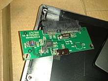
eSATA/eSATAp
The eSATA connector is a more robust SATA connector, intended for connection to external hard drives and SSDs. eSATA's transfer rate (up to 6 Gbit/s) is similar to that of USB 3.0 (up to 5 Gbit/s on current devices; 10 Gbit/s speeds via USB 3.1, announced on 31 July 2013). A device connected by eSATA appears as an ordinary SATA device, giving both full performance and full compatibility associated with internal drives.
eSATA does not supply power to external devices. This is an increasing disadvantage compared to USB. Even though USB 3.0's 4.5 W is sometimes insufficient to power external hard drives, technology is advancing and external drives gradually need less power, diminishing the eSATA advantage. eSATAp (power over eSATA; aka ESATA/USB) is a connector introduced in 2009 that supplies power to attached devices using a new, backward compatible, connector. On a notebook eSATAp usually supplies only 5 V to power a 2.5-inch HDD/SSD; on a desktop workstation it can additionally supply 12 V to power larger devices including 3.5-inch HDD/SSD and 5.25-inch optical drives.
eSATAp support can be added to a desktop machine in the form of a bracket connecting the motherboard SATA, power, and USB resources.
eSATA, like USB, supports hot plugging, although this might be limited by OS drivers and device firmware.
Thunderbolt
Thunderbolt combines PCI Express and Mini DisplayPort into a new serial data interface. Original Thunderbolt implementations have two channels, each with a transfer speed of 10 Gbit/s, resulting in an aggregate unidirectional bandwidth of 20 Gbit/s.[94]
Thunderbolt 2 uses link aggregation to combine the two 10 Gbit/s channels into one bidirectional 20 Gbit/s channel.
Thunderbolt 3 uses the USB-C connector.[95][96][97] Thunderbolt 3 has two physical 20 Gbit/s bi-directional channels, aggregated to appear as a single logical 40 Gbit/s bi-directional channel. Thunderbolt 3 controllers can incorporate a USB 3.1 Gen 2 controller to provide compatibility with USB devices. They are also capable of providing DisplayPort alternate mode over the USB-C connector, making a Thunderbolt 3 port a superset of a USB 3.1 Gen 2 port with DisplayPort alternate mode.
After the specification was made royalty-free and custodianship of the Thunderbolt protocol was transferred from Intel to the USB Implementers' Forum, Thunderbolt 3 has been effectively implemented in the USB4 specification – with compatibility with Thunderbolt 3 optional but encouraged for USB4 products — with Thunderbolt 4 being applied to products that are compatible with USB4's complete feature set.
Interoperability
Various protocol converters are available that convert USB data signals to and from other communications standards.
Security threats
- BadUSB[53], see also USB flash drive#BadUSB
- Intel cpus, from Skylake, allow to take control over them from USB 3.0.[98][99][100]
- USB Killer
- USB flash drives were dangerous for first versions of Windows XP because they were configured by default to execute program shown in Autorun.inf immediately after plugging flash drive in, malware could be automatically activated with usage of that.
See also
- DockPort
- Easy Transfer Cable
- Extensible Host Controller Interface (XHCI)
- LIO Target
- List of device bit rates#Peripheral
- Media Transfer Protocol
- Mobile High-Definition Link
- WebUSB
- USB-C
- Thunderbolt (interface)
References
- "82371FB (PIIX) and 82371SB (PIIX3) PCI ISA IDE Xcelerator" (PDF). Intel. May 1996. Archived from the original (PDF) on 13 March 2016. Retrieved 12 March 2016.
- "USB 'A' Plug Form Factor Revision 1.0" (PDF). USB Implementers Forum. 23 March 2005. p. 1. Archived (PDF) from the original on 19 May 2017. Retrieved 4 June 2017.
Body length is fully 12 mm in width by 4.5 mm in height with no deviations
- "USB deserves more support". Business. Boston Globe Online. Simson. 31 December 1995. Archived from the original on 6 April 2012. Retrieved 12 December 2011.
- Hachman, Mark (4 March 2019). "The new USB4 spec promises a lot: Thunderbolt 3 support, 40Gbps bandwidth, and less confusion". PCWorld. Retrieved 4 March 2019.
- Jan Axelson, USB Complete: The Developer's Guide, Fifth Edition, Lakeview Research LLC, 2015, ISBN 1931448280, pages 1-7
- "Definition of: how to install a PC peripheral". PC. Ziff Davis. Retrieved 17 February 2018.
- "Icon design recommendation for Identifying USB 2.0 Ports on PCs, Hosts and Hubs" (PDF). USB..
- Janssen, Cory. "What is a Universal Serial Bus (USB)?". Techopedia. Archived from the original on 3 January 2014. Retrieved 12 February 2014.
- "Intel Fellow: Ajay V. Bhatt". Intel Corporation. Archived from the original on 4 November 2009.
- Rogoway, Mark (9 May 2009). "Intel ad campaign remakes researchers into rock stars". The Oregonian. Archived from the original on 26 August 2009. Retrieved 23 September 2009.
- Pan, Hui; Polishuk, Paul (eds.). 1394 Monthly Newsletter. Information Gatekeepers. pp. 7–9. GGKEY:H5S2XNXNH99. Archived from the original on 12 November 2012. Retrieved 23 October 2012.
- Johnson, Joel (29 May 2019). "The history of USB, the port that changed everything". Fast Company.
- Seebach, Peter (26 April 2005). "Standards and specs: The ins and outs of USB". IBM. Archived from the original on 10 January 2010. Retrieved 8 September 2012.
- "Eight ways the iMac changed computing". Macworld. 15 August 2008. Archived from the original on 22 December 2011. Retrieved 5 September 2017.
- "Compaq hopes to follow the iMac". Archived from the original on 22 October 2006.
- "The PC Follows iMac's Lead". Business week. 1999. Archived from the original on 23 September 2015.
- Popular Mechanics: Making Connections. Hearst Magazines. February 2001. p. 59. ISSN 0032-4558. Archived from the original on 15 February 2017.
- Universal Serial Bus 3.0 Specification (ZIP). Hewlett-Packard Company Intel Corporation Microsoft Corporation NEC Corporation ST-Ericsson Texas Instruments. 6 June 2011. Archived from the original on 19 May 2014 – via www.usb.org.
"Universal Serial Bus 3.0 Specification" (PDF). 12 November 2008. Retrieved 29 December 2012 – via www.gaw.ru. - "USB 3.0 SuperSpeed gone wild at CES 2010, trumps even your new SSD". 9 January 2010. Archived from the original on 28 June 2011. Retrieved 20 February 2011.
- "USB 3.0 Finally Arrives". 11 January 2010. Archived from the original on 23 February 2011. Retrieved 20 February 2011.
- "SuperSpeed USB 3.0: More Details Emerge". PC world. 6 January 2009. Archived from the original on 24 January 2009.
- "IEC and USB-IF Expand Cooperation to Support Next-Generation High-Speed Data Delivery and Device Charging Applications" (PDF) (Press release). GENEVA, Switzerland and BEAVERTON, Ore., U.S. 8 December 2014. Archived (PDF) from the original on 29 December 2014.
- "4.2.1". Universal Serial Bus Specification (PDF) (Technical report). 1996. p. 29. v1.0. Archived (PDF) from the original on 30 January 2018.
- "USB 2.0 Specification". USB Implementers Forum. Archived from the original on 3 December 2017. Retrieved 28 April 2019.
- "Battery Charging v1.2 Spec and Adopters Agreement". USB Implementers Forum. 7 December 2010. Archived from the original (ZIP) on 6 October 2014. Retrieved 28 April 2019.
- "USB 3.0 Specification Now Available" (PDF) (Press release). San Jose, Calif. 17 November 2008. Archived from the original (PDF) on 31 March 2010. Retrieved 22 June 2010 – via usb.org.
- "USB 3.0 Technology" (PDF). HP. 2012. Archived from the original on 19 February 2015. Retrieved 2 January 2014.
- "USB 3.1 Specification – Language Usage Guidelines from USB-IF" (PDF). Archived (PDF) from the original on 12 March 2016 – via www.usb.org.
- Silvia (5 August 2015). "USB 3.1 Gen 1 & Gen 2 explained". www.msi.org.
- Universal Serial Bus 3.1 Specification. Hewlett-Packard Company Intel Corporation Microsoft Corporation Renesas Corporation ST-Ericsson Texas Instruments. 26 July 2013. Archived from the original (ZIP) on 21 November 2014. Retrieved 19 November 2014 – via www.usb.org.
- "The USB 3.2 Specification released on September 22, 2017 and ECNs". usb.org. 22 September 2017. Retrieved 4 September 2019.
- "USB 3.0 Promoter Group Announces USB 3.2 Update" (PDF) (Press release). Beaverton, OR, USA. 25 July 2017. Retrieved 27 July 2017 – via www.usb.org.
- "USB 3.2 Specification Language Usage Guidelines from USB-IF" (PDF). usb.org. 26 February 2019. Retrieved 4 September 2019.
- Ravencraft, Jeff (19 November 2019). "USB DevDays 2019 – Branding Session" (PDF) (Presentation). USB Implementers Forum. p. 16. Archived from the original (PDF) on 22 March 2020. Retrieved 22 March 2020. Lay summary – USB-IF (2 July 2020).
- "USB Promoter Group USB4 Specification". usb.org. 29 August 2019.
- Bright, Peter (4 March 2019). "Thunderbolt 3 becomes USB4, as Intel's interconnect goes royalty-free". Ars Technica. Retrieved 4 March 2019.
- Grunin, Lori (4 March 2019). "USB4 marries Thunderbolt 3 for faster speeds and smarter transfers". CNET. Retrieved 4 March 2019.
- Brant, Tom (4 March 2019). "Thunderbolt 3 Merges With USB to Become USB4". PC Magazine. Retrieved 4 March 2019.
- "USB Promoter Group USB4 Specification". usb.org. 29 August 2019.
- Peter Bright (26 July 2017). "USB 3.2 will make your cables twice as fast… once you've bought new devices". Ars Technica. Archived from the original on 27 July 2017. Retrieved 27 July 2017.
- "Battery Charging v1.1 Spec and Adopters Agreement". usb.org.
- "Battery Charging v1.2 Spec and Adopters Agreement". usb.org.
- "USB Power Delivery". usb.org.
- Universal Serial Bus Specification Revision 2.0. 11 October 2011. pp. 13, 30, 256. Archived from the original (ZIP) on 28 May 2012. Retrieved 8 September 2012.
- Dan Froelich (20 May 2009). "Isochronous Protocol" (PDF). usb.org. Archived from the original (PDF) on 17 August 2014. Retrieved 21 November 2014.
- "USB Class Codes". 22 September 2018. Archived from the original on 22 September 2018 – via www.usb.org.
- Use class information in the interface descriptors. This base class is defined to use in device descriptors to indicate that class information should be determined from the Interface Descriptors in the device.
- "Universal Serial Bus Test and Measurement Class Specification (USBTMC) Revision 1.0" (PDF). USB Implementers Forum. 14 April 2003. Retrieved 10 May 2018 – via sdpha2.ucsd.edu.
- "Universal Serial Bus Device Class Specification for Device Firmware Upgrade, Version 1.1" (PDF). USB Implementers Forum. 15 October 2004. pp. 8–9. Archived (PDF) from the original on 11 October 2014. Retrieved 8 September 2014.
- "100 Portable Apps for your USB Stick (both for Mac and Win)". Archived from the original on 2 December 2008. Retrieved 30 October 2008.
- "Skype VoIP USB Installation Guide". Archived from the original on 6 July 2014. Retrieved 30 October 2008.
- "PS/2 to USB Keyboard and Mouse Adapter". StarTech.com. Archived from the original on 12 November 2014.
- "Universal Serial Bus Device Class Specification for Device Firmware Upgrade, Version 1.0" (PDF). USB Implementers Forum. 13 May 1999. pp. 7–8. Archived from the original (PDF) on 24 August 2014. Retrieved 8 September 2014.
- "rpms/dfu-util: USB Device Firmware Upgrade tool". fedoraproject.org. 14 May 2014. Retrieved 8 September 2014.
- Karsten Nohl; Sascha Krißler; Jakob Lell (7 August 2014). "BadUSB – On accessories that turn evil" (PDF). srlabs.de. Security Research Labs. Archived from the original (PDF) on 8 August 2014. Retrieved 8 September 2014.
- "USB-IF Announces USB Audio Device Class 3.0 Specification". Business Wire (Press release). Houston, Texas & Beaverton, Oregon. 27 September 2016. Retrieved 4 May 2018.
- "USB Device Class Specifications". www.usb.org. Retrieved 4 May 2018.
- Strong, Laurence (2015). "Why do you need USB Audio Class 2?" (PDF). XMOS.
In applications where streaming latency is important, UAC2 offers up to an 8x reduction over UAC1. ... Each clocking method has pros and cons and best-fit applications.
- "USB Audio 2.0 Drivers". Microsoft Hardware Dev Center. Retrieved 4 May 2018.
ADC-2 refers to the USB Device Class Definition for Audio Devices, Release 2.0.
- Kars, Vincent (May 2011). "USB". The Well-Tempered Computer. Retrieved 7 May 2018.
All operating systems (Win, OSX, and Linux) support USB Audio Class 1 natively. This means you don’t need to install drivers, it is plug&play.
- "Fundamentals of USB Audio". www.xmos.com. XMOS. Retrieved 7 May 2018.
Note that Full Speed USB has a much higher intrinsic latency of 2ms
- "This Just In: Microsoft Launches Native Class 2 USB Audio Support. Wait, What?". Computer Audiophile. Retrieved 7 May 2018.
Class 2 support enables much higher sample rates such as PCM 24 bit / 384 kHz and DSD (DoP) up through DSD256.
- "New USB Audio Class for USB Type-C Digital Headsets". www.synopsys.com. Retrieved 7 May 2018.
- "Announcing Windows 10 Insider Preview Build 14931 for PC". Windows Experience Blog. Retrieved 7 May 2018.
We now have native support for USB Audio 2.0 devices with an inbox class driver! This is an early version of the driver that does not have all features enabled
- Plummer, Gregg (20 September 2017). "Ampliozone: USB Audio Class 2.0 Support in Windows 10, FINALLY!!!!". Ampliozone. Retrieved 7 May 2018.
- "USB Digital Audio". Android Open Source Project. Retrieved 7 May 2018.
Synchronous sub-mode is not commonly used with audio because both host and peripheral are at the mercy of the USB clock.
- "32-bit Atmel Microcontroller Application Note" (PDF). Atmel Corporation. 2011. Archived (PDF) from the original on 6 May 2016. Retrieved 13 April 2016.
- "PCM2906C datasheet" (PDF). Texas Instruments. November 2011.
The PCM2906C employs SpAct™ architecture, TI's unique system that recovers the audio clock from USB packet data.
- Castor-Perry, Kendall (October 2010). "Designing Modern USB Audio Systems". Cypress Semiconductor.
- Castor-Perry, Kendall (2011). "Programmable Clock Generation and Synchronization for USB Audio Systems". Cypress Semiconductor.
Early USB replay interfaces used synchronous mode but acquired a reputation for poor quality of the recovered clock (and resultant poor replay quality). This was primarily due to deficiencies of clocking implementation rather than inherent shortcomings of the approach.
- Kondoh, Hitoshi (20 February 2002). "The D/A diaries: A personal memoir of engineering heartache and triumph" (PDF).
The fact that there is no clock line within the USB cable leads to a thinner cable, which is an advantage. But, no matter how good the crystal oscillators are at the send and receive ends, there will always be some difference between the two...
- "USB 2.0 Documents". www.usb.org. Retrieved 7 May 2018.
- "Our Guide to USB Audio - Why Should I Use it?". Cambridge Audio. Retrieved 7 May 2018.
Synchronous USB DAC is the lowest quality of the three ... Adaptive ... means that there is no continuous, accurate master clock in the DAC, which causes jitter in the audio stream. ... Asynchronous – this is the most complex to implement but it is a huge improvement on the other types.
- Kars, Vincent (July 2012). "USB versus USB". The Well-Tempered Computer. Retrieved 7 May 2018.
Synchronous is not used in a quality DAC as it is very jittery. ... asynchronous is the better of these modes.
- "Low-Jitter USB: Dan Lavry, Michael Goodman, Adaptive, Asynchronous". Headphone Reviews and Discussion - Head-Fi.org. Retrieved 7 May 2018.
Some manufacturers may lead you to believe that Asynchronous USB transfers are superior to Adaptive USB transfers and that therefore you must believe in the asynchronous solution. This no more true than saying that you "must" hold the fork in your left hand. In fact, if you know what you are doing, you will feed yourself with either hand. The issue is really about good engineering practices.
- "USB 2.0 Specification Engineering Change Notice (ECN) #1: Mini-B connector" (PDF). 20 October 2000. Archived (PDF) from the original on 12 April 2015. Retrieved 29 December 2014 – via www.usb.org.
- "USB Cable Length Limitations" (PDF). cablesplususa.com. 3 November 2010. Archived from the original (PDF) on 11 October 2014. Retrieved 2 February 2014.
- "What is the Maximum Length of a USB Cable?". Techwalla.com. Archived from the original on 1 December 2017. Retrieved 18 November 2017.
- "Cables and Long-Haul Solutions". USB 2.0 Frequently Asked Questions. USB Implementers Forum. Archived from the original on 18 January 2011. Retrieved 28 April 2019.
- Axelson, Jan. "USB 3.0 Developers FAQ". Archived from the original on 20 December 2016. Retrieved 20 October 2016.
- "Parameter Values". Battery Charging Specification, Revision 1.2. USB Implementers Forum. 7 December 2010. p. 45. Archived from the original on 28 March 2016. Retrieved 29 March 2016.
- "USB in a NutShell – Chapter 2: Hardware". Beyond Logic.org. Archived from the original on 20 August 2007. Retrieved 25 August 2007.
- Kurt Shuler (31 March 2011). "Interchip Connectivity: HSIC, UniPro, HSI, C2C, LLI... oh my!". Arteris IP. Archived from the original on 19 June 2011. Retrieved 24 June 2011.
- "FireWire vs. USB 2.0" (PDF). QImaging. Archived (PDF) from the original on 11 October 2010. Retrieved 20 July 2010.
- "FireWire vs. USB 2.0 – Bandwidth Tests". Archived from the original on 12 August 2007. Retrieved 25 August 2007.
- "USB 2.0 vs FireWire". Pricenfees. Archived from the original on 16 October 2016. Retrieved 25 August 2007.
- Metz, Cade (25 February 2003). "The Great Interface-Off: FireWire Vs. USB 2.0". PC Magazine. Archived from the original on 30 September 2007. Retrieved 25 August 2007.
- Heron, Robert. "USB 2.0 Versus FireWire". TechTV. Archived from the original on 29 September 2007. Retrieved 25 August 2007.
- "FireWire vs. USB 2.0". USB Ware. Archived from the original on 16 March 2007. Retrieved 19 March 2007.
- Key, Gary (15 November 2005). "Firewire and USB Performance". Archived from the original on 23 April 2008. Retrieved 1 February 2008.
- "802.3, Section 14.3.1.1" (PDF). IEEE. Archived (PDF) from the original on 6 December 2010.
- "Powerbook Explodes After Comcast Plugs in Wrong Cable". Consumerist. 8 March 2010. Archived from the original on 25 June 2010. Retrieved 22 June 2010.
- https://www.usb.org/sites/default/files/midi10.pdf
- "How Thunderbolt Technology Works: Thunderbolt Technology Community". Thunderbolttechnology.net. Archived from the original on 10 February 2014. Retrieved 22 January 2014.
- "One port to rule them all: Thunderbolt 3 and USB Type-C join forces". Archived from the original on 2 June 2015. Retrieved 2 June 2015.
- "Thunderbolt 3 is twice as fast and uses reversible USB-C". Archived from the original on 3 June 2015. Retrieved 2 June 2015.
- Sebastian Anthony (2 June 2015). "Thunderbolt 3 embraces USB Type-C connector, doubles bandwidth to 40 Gbps". Ars Technica. Archived from the original on 9 June 2015. Retrieved 2 June 2015.
- https://www.ptsecurity.com/ww-en/analytics/where-theres-a-jtag-theres-a-way/
- https://www.youtube.com/watch?v=2JCUrG7ERIE
- https://habr.com/ru/company/pt/blog/318744/
Further reading
- Axelson, Jan (1 September 2006). USB Mass Storage: Designing and Programming Devices and Embedded Hosts (1st ed.). Lakeview Research. ISBN 978-1-931-44804-8.
- ——— (1 December 2007). Serial Port Complete: COM Ports, USB Virtual COM Ports, and Ports for Embedded Systems (2nd ed.). Lakeview Research. ISBN 978-1-931-44806-2.
- ——— (2015). USB Complete: The Developer's Guide (5th ed.). Lakeview Research. ISBN 978-1-931448-28-4.
- Hyde, John (February 2001). USB Design by Example: A Practical Guide to Building I/O Devices (2nd ed.). Intel Press. ISBN 978-0-970-28465-5.
- "Debugging USB 2.0 for Compliance: It's Not Just a Digital World" (PDF). Keysight Technologies. Technologies Application Note. Keysight (1382–3).
External links
| Wikimedia Commons has media related to Universal Serial Bus. |
| The Wikibook Serial Programming:USB Technical Manual has a page on the topic of: USB connectors |
- "USB Implementers Forum".
- USB Document Library (USB 3.2, USB 2.0, Wireless USB, USB-C, USB Power Delivery)
- "Universal Host Controller Interface (UHCI)" (PDF). Intel. Cite journal requires
|journal=(help) - "USB 3.0 Standard-A, Standard-B, Powered-B connectors". Pinouts guide. Cite journal requires
|journal=(help) - "Characterization and compliance test". Agilent. Cite journal requires
|journal=(help) - Muller, Henk. "How To Create And Program USB Devices," Electronic Design, July 2012
- An Analysis of Throughput Characteristics of Universal Serial Bus, June 1996, by John Garney
- The unlikely origins of USB, the port that changed everything - Oral history
- USB 2.0 Protocol Engine, October 2010, by Razi Hershenhoren and Omer Reznik
- IEC 62680 (Universal Serial Bus interfaces for data and power):
- IEC 62680-1.1:2015 - Part 1-1: Common components - USB Battery Charging Specification, Revision 1.2
- IEC 62680-1-2:2018 - Part 1-2: Common components - USB Power Delivery specification
- IEC 62680-1-3:2018 - Part 1-3: Common components - USB Type-C™ Cable and Connector Specification
- IEC 62680-1-4:2018 - Part 1-4: Common components - USB Type-C™ Authentication Specification
- IEC 62680-2-1:2015 - Part 2-1: Universal Serial Bus Specification, Revision 2.0
- IEC 62680-2-2:2015 - Part 2-2: Micro-USB Cables and Connectors Specification, Revision 1.01
- IEC 62680-2-3:2015 - Part 2-3: Universal Serial Bus Cables and Connectors Class Document Revision 2.0
- IEC 62680-3-1:2017 - Part 3-1: Universal Serial Bus 3.1 Specification
| Authority control |
|---|
Technical and de facto standards for wired computer buses | |
|---|---|
| General |
|
| Standards |
|
| Storage |
|
| Peripheral |
|
| Audio |
|
| Portable |
|
| Embedded |
|
Interfaces are listed by their speed in the (roughly) ascending order, so the interface at the end of each section should be the fastest. | |
| Key terminology |
| ||||
|---|---|---|---|---|---|
| Flash manufacturers | |||||
| Controllers |
| ||||
| SSD manufacturers |
| ||||
| Interfaces |
| ||||
| Configurations |
| ||||
| Related organizations |
| ||||
| |||||