USB-C
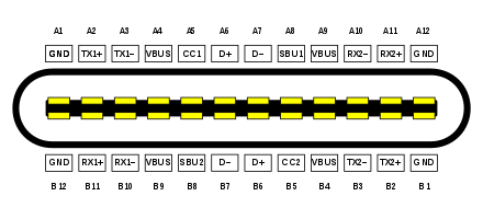
USB-C, formally known as USB Type-C, is a 24-pin USB connector system, which is distinguished by its almost two-fold rotationally-symmetrical connector.[2] (Symmetry is broken, typically by a seam in the outer metal mating surface)
|
| |||
| Type | Digital audio / video / data connector / power | ||
|---|---|---|---|
| Production history | |||
| Designer | USB Implementers Forum | ||
| Designed | 11 August 2014 (published)[1] | ||

The USB Type-C Specification 1.0 was published by the USB Implementers Forum (USB-IF) and was finalized in August 2014.[3] It was developed at roughly the same time as the USB 3.1 specification. In July 2016, it was adopted by the IEC as "IEC 62680-1-3".[4]
A device with a Type-C connector does not necessarily implement USB, USB Power Delivery, or any Alternate Mode: the Type-C connector is common to several technologies while mandating only a few of them.[5][6]
USB 3.2, released in September 2017, replaces the USB 3.1 standard. It preserves existing USB 3.1 SuperSpeed and SuperSpeed+ data modes and introduces two new SuperSpeed+ transfer modes over the USB-C connector using two-lane operation, with data rates of 10 and 20 Gbit/s (1 and ~2.4 GB/s).
Overview
USB-C connectors and cables connect to both hosts and devices, replacing various electrical connectors including USB-B and USB-A, HDMI, DisplayPort and 3.5 mm audio cables and connectors.[7][3]
Name
USB Type-C and USB-C are trademarks of USB Implementers Forum.[8]
Connectors


The 24-pin double-sided connector is slightly larger than the micro-B connector, with a USB-C port measuring 8.4 millimetres (0.33 in) by 2.6 millimetres (0.10 in). Two kinds (genders) of connectors exist, female (receptacle) and male (plug).
Plugs are found on cables and adapters. Receptacles are found on devices and adapters.
Cables
USB 3.1 cables are considered full-featured USB-C cables. They are electronically marked cables that contain a chip with an ID function based on the configuration channel and vendor-defined messages (VDM) from the USB Power Delivery 2.0 specification. Cable length should be ≤2 m for Gen 1 or ≤1 m for Gen 2.[9] The electronic ID chip provides information about product/vendor, cable connectors, USB signalling protocol (2.0, Gen 1, Gen 2), passive/active construction, use of VCONN power, available VBUS current, latency, RX/TX directionality, SOP controller mode, and hardware/firmware version.[6]
USB-C cables that do not have shielded SuperSpeed pairs, sideband use pins, or additional wires for power lines can have increased cable length, up to 4 m. These USB-C cables only support 2.0 speeds and do not support alternate modes.
All USB-C cables must be able to carry a minimum of 3 A current (at 20 V, 60 W) but can also carry high-power 5 A current (at 20 V, 100 W).[10] USB-C to USB-C cables supporting 5A current must contain e-marker chips programmed to identify the cable and its current capabilities. USB Charging ports should also be clearly marked with capable power wattage.[11]
Full-featured USB-C cables that implement USB 3.1 Gen 2 can handle up to 10 Gbit/s data rate at full duplex. They are marked with a SuperSpeed+ (SuperSpeed 10 Gbit/s) logo. There are also cables which can carry only USB 2.0 with up to 480 Mbit/s data rate. There are USB-IF certification programs available for USB-C products and end users are recommended to use USB-IF certified cables.[12]
Devices
Devices may be hosts (DFP: downstream-facing port) or peripherals (UFP: upstream-facing port). Some, such as mobile phones, can take either role depending on what kind is detected on the other end. These types of ports are called Dual-Role-Data (DRD) ports, which was known as USB On-The-Go in the previous specification.[13] When two such devices are connected, the roles are randomly assigned but a swap can be commanded from either end, although there are optional path and role detection methods that would allow devices to select a preference for a specific role. Furthermore, dual-role devices that implement USB Power Delivery may independently and dynamically swap data and power roles using the Data Role Swap or Power Role Swap processes. This allows for charge-through hub or docking station applications where the USB-C device acts as a USB data host while acting as a power consumer rather than a source.[6]
USB-C devices may optionally provide or consume bus power currents of 1.5 A and 3.0 A (at 5 V) in addition to baseline bus power provision; power sources can either advertise increased USB current through the configuration channel, or they can implement the full USB Power Delivery specification using both BMC-coded configuration line and legacy BFSK-coded VBUS line.[6][11]
Connecting an older device to a host with a USB-C receptacle requires a cable or adapter with a USB-A or USB-B plug or receptacle on one end and a USB-C plug on the other end. Legacy adapters (i.e. adapters with a USB-A or USB-B plug) with a USB-C receptacle are "not defined or allowed" by the specification because they can create "many invalid and potentially unsafe" cable combinations.[14]
Modes
Audio Adapter Accessory Mode
A device with a USB-C port may support analog headsets through an audio adapter with a 3.5 mm jack, providing four standard analog audio connections (Left, Right, Microphone, and Ground). The audio adapter may optionally include a USB-C charge-through port to allow 500 mA device charging. The engineering specification states that an analog headset shall not use a USB-C plug instead of a 3.5 mm plug. In other words, headsets with a USB-C plug should always support digital audio (and optionally the accessory mode).[15]
Analog signals use the USB 2.0 differential pairs (Dp and Dn for Right and Left) and the two side-band use pairs for Mic and GND. The presence of the audio accessory is signalled through the configuration channel and VCONN.
Alternate Mode
An Alternate Mode dedicates some of the physical wires in a USB-C 3.1 cable for direct device-to-host transmission of alternate data protocols. The four high-speed lanes, two side-band pins, and (for dock, detachable device and permanent cable applications only) two USB 2.0 data pins and one configuration pin can be used for alternate mode transmission. The modes are configured using vendor-defined messages (VDM) through the configuration channel.
Specifications
USB Type-C Cable and Connector Specification
The USB Type-C specification 1.0 was published by the USB Implementers Forum (USB-IF) and was finalized in August 2014.[3]
It defines requirements for cables and connectors.
- Rev 1.1 was published 2015-04-03[16]
- Rev 1.2 was published 2016-03-25[17]
- Rev 1.3 was published 2017-07-14 (release date included in Rev. 1.4)[18]
- Rev 1.4 was published 2019-03-29[18]
- Rev 2.0 was published 2019-08[19]
Adoption as IEC specification:
- IEC 62680-1-3:2016 (2016-08-17, edition 1.0) "Universal serial bus interfaces for data and power – Part 1-3: Universal Serial Bus interfaces – Common components – USB Type-C cable and connector specification"[20]
- IEC 62680-1-3:2017 (2017-09-25, edition 2.0) "Universal serial bus interfaces for data and power – Part 1-3: Common components – USB Type-C Cable and Connector Specification"[21]
- IEC 62680-1-3:2018 (2018-05-24, edition 3.0) "Universal serial bus interfaces for data and power – Part 1-3: Common components – USB Type-C Cable and Connector Specification"[22]
Receptacles
The receptacle features four power and four ground pins, two differential pairs for high-speed USB data (though they are connected together on devices), four shielded differential pairs for Enhanced SuperSpeed data (two transmit and two receive pairs), two Sideband Use (SBU) pins, and two Configuration Channel (CC) pins.
| Pin | Name | Description |
|---|---|---|
| A1 | GND | Ground return |
| A2 | SSTXp1 | SuperSpeed differential pair #1, TX, positive |
| A3 | SSTXn1 | SuperSpeed differential pair #1, TX, negative |
| A4 | VBUS | Bus power |
| A5 | CC1 | Configuration channel |
| A6 | Dp1 | USB 2.0 differential pair, position 1, positive |
| A7 | Dn1 | USB 2.0 differential pair, position 1, negative |
| A8 | SBU1 | Sideband use (SBU) |
| A9 | VBUS | Bus power |
| A10 | SSRXn2 | SuperSpeed differential pair #4, RX, negative |
| A11 | SSRXp2 | SuperSpeed differential pair #4, RX, positive |
| A12 | GND | Ground return |
| Pin | Name | Description |
|---|---|---|
| B12 | GND | Ground return |
| B11 | SSRXp1 | SuperSpeed differential pair #2, RX, positive |
| B10 | SSRXn1 | SuperSpeed differential pair #2, RX, negative |
| B9 | VBUS | Bus power |
| B8 | SBU2 | Sideband use (SBU) |
| B7 | Dn2 | USB 2.0 differential pair, position 2, negative[lower-alpha 1] |
| B6 | Dp2 | USB 2.0 differential pair, position 2, positive[lower-alpha 1] |
| B5 | CC2 | Configuration channel |
| B4 | VBUS | Bus power |
| B3 | SSTXn2 | SuperSpeed differential pair #3, TX, negative |
| B2 | SSTXp2 | SuperSpeed differential pair #3, TX, positive |
| B1 | GND | Ground return |
Notes
- There is only a single non-SuperSpeed differential pair in the cable. This pin is not connected in the plug/cable.
Plugs
The male connector (plug) has only one high-speed differential pair, and one of the CC pins is replaced by VCONN(CC2), to power electronics in the cable, and the other is used to actually carry the Configuration Channel signals. These signals are used to determine the orientation of the cable, as well as to carry USB Power Delivery communications.

Cables
| Plug 1, USB Type-C | USB Type-C cable | Plug 2, USB Type-C | ||||||
|---|---|---|---|---|---|---|---|---|
| Pin | Name | Wire color | No | Name | Description | 2.0[lower-alpha 1] | Pin | Name |
| Shell | Shield | Braid | Braid | Shield | Cable external braid | ✓ | Shell | Shield |
| A1, B12, B1, A12 |
GND | Tin-plated | 1 | GND_PWRrt1 | Ground for power return | ✓ | A1, B12, B1, A12 |
GND |
| 16 | GND_PWRrt2 | ✗ | ||||||
| A4, B9, B4, A9 |
VBUS | Red | 2 | PWR_VBUS1 | VBUS power | ✓ | A4, B9, B4, A9 |
VBUS |
| 17 | PWR_VBUS2 | ✗ | ||||||
| B5 | VCONN | Yellow |
18 | PWR_VCONN | VCONN power, for powered cables[lower-alpha 2] | ✓ | B5 | VCONN |
| A5 | CC | Blue | 3 | CC | Configuration channel | ✓ | A5 | CC |
| A6 | Dp1 | Green | 4 | UTP_Dp[lower-alpha 3] | Unshielded twisted pair, positive | ✓ | A6 | Dp1 |
| A7 | Dn1 | White | 5 | UTP_Dn[lower-alpha 3] | Unshielded twisted pair, negative | ✓ | A7 | Dn1 |
| A8 | SBU1 | Red | 14 | SBU_A | Sideband use A | ✗ | B8 | SBU2 |
| B8 | SBU2 | Black | 15 | SBU_B | Sideband use B | ✗ | A8 | SBU1 |
| A2 | SSTXp1 | Yellow[lower-alpha 4] | 6 | SDPp1 | Shielded differential pair #1, positive | ✗ | B11 | SSRXp1 |
| A3 | SSTXn1 | Brown[lower-alpha 4] | 7 | SDPn1 | Shielded differential pair #1, negative | ✗ | B10 | SSRXn1 |
| B11 | SSRXp1 | Green[lower-alpha 4] | 8 | SDPp2 | Shielded differential pair #2, positive | ✗ | A2 | SSTXp1 |
| B10 | SSRXn1 | Orange[lower-alpha 4] | 9 | SDPn2 | Shielded differential pair #2, negative | ✗ | A3 | SSTXn1 |
| B2 | SSTXp2 | White[lower-alpha 4] | 10 | SDPp3 | Shielded differential pair #3, positive | ✗ | A11 | SSRXp2 |
| B3 | SSTXn2 | Black[lower-alpha 4] | 11 | SDPn3 | Shielded differential pair #3, negative | ✗ | A10 | SSRXn2 |
| A11 | SSRXp2 | Red[lower-alpha 4] | 12 | SDPp4 | Shielded differential pair #4, positive | ✗ | B2 | SSTXp2 |
| A10 | SSRXn2 | Blue[lower-alpha 4] | 13 | SDPn4 | Shielded differential pair #4, negative | ✗ | B3 | SSTXn2 |
| ||||||||
Related USB-IF specifications
USB Type-C Locking Connector Specification
The USB Type-C Locking Connector Specification was published 2016-03-09. It defines the mechanical requirements for USB-C plug connectors and the guidelines for the USB-C receptacle mounting configuration to provide a standardized screw lock mechanism for USB-C connectors and cables.[23]
USB Type-C Port Controller Interface Specification
The USB Type-C Port Controller Interface Specification was published 2017-10-01. It defines a common interface from a USB-C Port Manager to a simple USB-C Port Controller.[24]
USB Type-C Authentication Specification
Adopted as IEC specification:
- IEC 62680-1-4:2018 (2018-04-10) "Universal Serial Bus interfaces for data and power - Part 1-4: Common components - USB Type-C™ Authentication Specification"[25]
USB 2.0 Billboard Device Class Specification
USB 2.0 Billboard Device Class is defined to communicate the details of supported Alternate Modes to the computer host OS. It provides user readable strings with product description and user support information. Billboard messages can be used to identify incompatible connections made by users. They are not required to negotiate Alternate Modes and only appear when negotiation fails between the host (source) and device (sink).
USB Audio Device Class 3.0 Specification
USB Audio Device Class 3.0 defines powered digital audio headsets with a USB-C plug.[6] The standard supports the transfer of both digital and analog audio signals over the USB port.[26]
USB Power Delivery Specification
While it is not necessary for USB-C compliant devices to implement USB Power Delivery, for USB-C DRP/DRD (Dual-Role-Power/Data) ports, USB Power Delivery introduces commands for altering a port's power or data role after the roles have been established when a connection is made.[27]
USB 3.2 Specification
USB 3.2, released in September 2017, replaces the USB 3.1 standard. It preserves existing USB 3.1 SuperSpeed and SuperSpeed+ data modes and introduces two new SuperSpeed+ transfer modes over the USB-C connector using two-lane operation, doubling the data rates to 10 and 20 Gbit/s (1 and ~2.4 GB/s).
Alternate Mode partner specifications
As of 2018, five system-defined Alternate Mode partner specifications exist. Additionally, vendors may support proprietary modes for use in dock solutions. Alternate Modes are optional; USB-C features and devices are not required to support any specific Alternate Mode. The USB Implementers Forum is working with its Alternate Mode partners to make sure that ports are properly labelled with respective logos.[28]
| Logo | Name | Date | Protocol |
|---|---|---|---|
| DisplayPort Alternate Mode | Published in September 2014 | DisplayPort 1.4[29][30] | |
| Mobile High-Definition Link (MHL) Alternate Mode | Announced in November 2014[31] | MHL 1.0, 2.0, 3.0 and superMHL 1.0[32][33][34][35] | |
| Thunderbolt Alternate Mode | Announced in June 2015[36] | Thunderbolt 3 (also carries DisplayPort 1.2 or DisplayPort 1.4)[36][37][38][39] | |
| HDMI Alternate Mode | Announced in September 2016[40] | HDMI 1.4b[41][42][43][44] | |
| VirtualLink Alternate Mode | Announced in July 2018[45] | VirtualLink 1.0 (not yet standardized)[46] |
Other protocols like Ethernet[47] have been proposed.
All Thunderbolt 3 controllers both support "Thunderbolt Alternate Mode" and "DisplayPort Alternate Mode".[48] Because Thunderbolt can encapsulate DisplayPort data, every Thunderbolt controller can either output DisplayPort signals directly over "DisplayPort Alternative Mode" or encapsulated within Thunderbolt in "Thunderbolt Alternate Mode". Low cost peripherals mostly connect via "DisplayPort Alternate Mode" while some docking stations tunnel DisplayPort over Thunderbolt.[49]
The USB SuperSpeed protocol is similar to DisplayPort and PCIe/Thunderbolt, in using packetized data transmitted over differential LVDS lanes with embedded clock using comparable bit rates, so these Alternate Modes are easier to implement in the chipset.[29]
Alternate Mode hosts and sinks can be connected with either regular full-featured USB-C cables, or with converter cables or adapters:
- USB 3.1 Type-C to Type-C full-featured cable
- DisplayPort, Mobile High-Definition Link (MHL), HDMI and Thunderbolt (20 Gbit/s, or 40 Gbit/s with cable length up to 0.5 m) Alternate Mode USB-C ports can be interconnected with standard passive full-featured USB Type-C cables. These cables are only marked with standard "trident" SuperSpeed USB logo (for Gen 1 cables) or the SuperSpeed+ USB 10 Gbit/s logo (for Gen 2 cables) on both ends.[50] Cable length should be 2.0 m or less for Gen 1 and 1.0 m or less for Gen 2.
- Thunderbolt Type-C to Type-C active cable
- Thunderbolt 3 (40 Gbit/s) Alternate Mode with cables longer than 0.5 m requires active USB-C cables that are certified and electronically marked for high-speed Thunderbolt 3 transmission, similarly to high-power 5 A cables.[36][39] These cables are marked with a Thunderbolt logo on both ends. They do not support USB 3 backwards compatibility, only USB 2 or Thunderbolt. Cables can be marked for both Thunderbolt and 5 A power delivery at the same time.[51]
- USB 3.1 Type-C adapter cable (plug) or adapter (socket)
- These cables or adapters contain a valid DisplayPort, HDMI, or MHL plug/socket marked with the logo of the required Alternate Mode, and a USB-C plug with a "trident" SuperSpeed 10 Gbit/s logo on the other end. Cable length should be 0.15 m or less .
Active cables/adapters contain powered ICs to amplify/equalise the signal for extended length cables, or to perform active protocol conversion. The adapters for video Alt Modes may allow conversion from native video stream to other video interface standards (e.g., DisplayPort, HDMI, VGA or DVI).
Using full-featured USB-C cables for Alternate Mode connections provides some benefits. Alternate Mode does not employ USB 2.0 lanes and the configuration channel lane, so USB 2.0 and USB Power Delivery protocols are always available. In addition, DisplayPort and MHL Alternate Modes can transmit on one, two, or four SuperSpeed lanes, so two of the remaining lanes may be used to simultaneously transmit USB 3.1 data.[52]
| Mode | USB 3.1 Type-C cable[lower-alpha 1] | Adapter cable or adapter | Construction | ||||||||||
|---|---|---|---|---|---|---|---|---|---|---|---|---|---|
| USB | DisplayPort | Thunderbolt | superMHL | HDMI | HDMI | DVI-D | Component video | ||||||
| 3.1 | 1.2 | 1.4 | 20 Gbit/s | 40 Gbit/s | 1.4b | 1.4b | 2.0b | single-link | dual-link | (YPbPr, VGA/DVI-A) | |||
| DisplayPort | Yes | Yes | No | Passive | |||||||||
| Optional | Yes | Yes | Yes | Active | |||||||||
| Thunderbolt | Yes[lower-alpha 3] | Yes[lower-alpha 3] | Yes | Yes[lower-alpha 4] | No | Passive | |||||||
| Optional | Optional | Yes | Yes | Yes | Yes | Active | |||||||
| MHL | Yes | Yes | Yes | No | Yes | No | No | Passive | |||||
| Optional | Yes | Yes | Active | ||||||||||
| HDMI | Yes | Yes | No | Yes | No | No | Passive | ||||||
| Optional | Yes | Active | |||||||||||
- USB 2.0 and USB Power Delivery are available at all times in a Type-C cable
- Is only available in Thunderbolt 3 DisplayPort mode.
- Thunderbolt 3 40 Gbit/s passive cables are only possible <0.5 m due to limitations of current cable technology.
USB-C receptacle pin usage in different modes
The diagrams below depict the pins of a USB-C socket in different use cases.
USB 2.0/1.1
A simple USB 2.0/1.1 device mates using one pair of D+/D− pins. Hence, the source (host) does not require any connection management circuitry, and therefore USB-C is backward compatible with even the oldest USB devices. VBUS and GND provide 5 V up to 500 mA of current. However, to connect a USB 2.0/1.1 device to a USB-C host, use of Rd[53] on the CC pins is required, as the source (host) will not supply VBUS until a connection is detected through the CC pins.
| GND | TX1+ | TX1− | VBUS | CC1 | D+ | D− | SBU1 | VBUS | RX2− | RX2+ | GND |
| GND | RX1+ | RX1− | VBUS | SBU2 | D− | D+ | CC2 | VBUS | TX2− | TX2+ | GND |
USB Power Delivery
USB Power Delivery uses one of CC1, CC2 pins for power negotiation up to 20 V at 5 A (or whatever less the source can provide). It is transparent to any data transmission mode, and can therefore be used together with any of them as long as the CC pins are not clobbered.
| GND | TX1+ | TX1− | VBUS | CC1 | D+ | D− | SBU1 | VBUS | RX2− | RX2+ | GND |
| GND | RX1+ | RX1− | VBUS | SBU2 | D− | D+ | CC2 | VBUS | TX2− | TX2+ | GND |
USB 3.0/3.1/3.2
In the USB 3.0/3.1/3.2 mode, two or four high speed links are used in TX/RX pairs to provide 5 to 10, or 10 to 20 Gbit/s throughput respectively. One of the CC pins is used to negotiate the mode.
VBUS and GND provide 5 V up to 900 mA, in accordance with the USB 3.1 specification. A specific USB-C mode may also be entered, where 5 V at either 1.5 A or 3 A is provided.[54] A third alternative is to establish a Power Delivery contract.
In single-lane mode, only the differential pairs closest to the CC pin are used for data transmission. For dual-lane data transfers, all four differential pairs are in use.
The D+/D− link for USB 2.0/1.1 is typically not used when USB 3.x connection is active, but devices like hubs open simultaneous 2.0 and 3.x uplinks in order to allow operation of both type devices connected to it. Other devices may have fallback mode to 2.0, in case the 3.x connection fails.
| GND | TX1+ | TX1− | VBUS | CC1 | D+ | D− | SBU1 | VBUS | RX2− | RX2+ | GND |
| GND | RX1+ | RX1− | VBUS | SBU2 | D− | D+ | CC2 | VBUS | TX2− | TX2+ | GND |
Alternate Mode
In the Alternate Mode one of up to four high speed links are used in whatever direction is needed. SBU1, SBU2 provide an additional lower speed link. If two high speed links remain unused, then a USB 3.0/3.1 link can be established concurrently to the Alternate Mode.[30] One of the CC pins is used to perform all the negotiation. An additional low band bidirectional channel (other than SBU) may share that CC pin as well.[30][41] USB 2.0 is also available through D+/D− pins.
In regard to power, the devices are supposed to negotiate a Power Delivery contract before an alternate mode is entered.[55]
| GND | TX1+ | TX1− | VBUS | CC1 | D+ | D− | SBU1 | VBUS | RX2− | RX2+ | GND |
| GND | RX1+ | RX1− | VBUS | SBU2 | D− | D+ | CC2 | VBUS | TX2− | TX2+ | GND |
Debug Accessory Mode
The external device test system signals to the target system to enter debug accessory mode via CC1 and CC2 both being pulled down with an Rn resistor value or pulled up as Rp resistor value from the test plug (Rp and Rn specified in Type-C spec).
After entering debug accessory mode, optional orientation detection via the CC1 and CC2 is done via setting CC1 as a pullup of Rd resistance and CC2 pulled to ground via Ra resistance (From the test system type-c plug). While optional, orientation detection is required if USB Power Delivery communication is to remain functional.
In this mode, all digital circuits are disconnected from the connector, and 14 underlined pins can be used to expose debug related signals (e.g. JTAG interface). USB IF requires for certification that security and privacy consideration and precaution has been taken and that the user has actually requested that debug test mode be performed.
| GND | TX1+ | TX1− | VBUS | CC1 | D+ | D− | SBU1 | VBUS | RX2− | RX2+ | GND |
| GND | RX1+ | RX1− | VBUS | SBU2 | D− | D+ | CC2 | VBUS | TX2− | TX2+ | GND |
If a reversible Type-C cable is required but Power Delivery support is not, the test plug will need to be arranged as below, with CC1 and CC2 both being pulled down with an Rn resistor value or pulled up as Rp resistor value from the test plug:
| GND | TS1 | TS2 | VBUS | CC1 | TS6 | TS7 | TS5 | VBUS | TS4 | TS3 | GND |
| GND | TS3 | TS4 | VBUS | TS5 | TS7 | TS6 | CC2 | VBUS | TS2 | TS1 | GND |
This mirroring of test signals will only provide 7 test signals for debug usage instead of 14, but with the benefit of minimising extra parts count for orientation detection.
Audio Adapter Accessory Mode
In this mode, all digital circuits are disconnected from the connector, and certain pins become reassigned for analog outputs or inputs. The mode, if supported, is entered when both CC pins are shorted to GND. D− and D+ become audio output left L and right R, respectively. The SBU pins become a microphone pin MIC, and the analog ground AGND, the latter being a return path for both outputs and the microphone. Nevertheless, the MIC and AGND pins must have automatic swap capability, for two reasons: firstly, the USB-C plug may be inserted either side; secondly, there is no agreement, which TRRS rings shall be GND and MIC, so devices equipped with a headphone jack with microphone input must be able to perform this swap anyway.[56]
This mode also allows concurrent charging of a device exposing the analog audio interface (through VBUS and GND), however only at 5 V and 500 mA, as CC pins are unavailable for any negotiation.
| GND | TX1+ | TX1− | VBUS | CC1 | R | L | MIC | VBUS | RX2− | RX2+ | GND |
| GND | RX1+ | RX1− | VBUS | AGND | L | R | CC2 | VBUS | TX2− | TX2+ | GND |
Plug insertions detection is performed by the TRRS plug's physical plug detection switch. On plug insertions, this will pull down both CC and VCONN in the plug (CC1 and CC2 in the receptacle). This resistance must be less than 800 ohms which is the minimum "Ra" resistance specified in the USB Type-C specification). This is essentially a direct connection to USB digital ground.
| TRRS socket | Analog audio signal | USB Type-C male plug |
|---|---|---|
| Tip | L | D− |
| Ring 1 | R | D+ |
| Ring 2 | Microphone/ground | SBU1 or SBU2 |
| Sleeve | Microphone/ground | SBU2 or SBU1 |
| DETECT1 | Plug presence detection switch | CC, VCONN |
| DETECT2 | Plug presence detection switch | GND |
Software support
- Android from version 6.0 onwards works with USB 3.1 and USB-C.[57]
- Chrome OS, starting with the Chromebook Pixel 2015, supports USB 3.1, USB-C, alternate modes, power delivery, and USB Dual-Role support.[58]
- FreeBSD released the Extensible Host Controller Interface, supporting USB 3.0, with release 8.2[59]
- iOS from version 12.1 (iPad Pro 3rd generation only) onwards works with USB-C.
- NetBSD began supporting USB 3.0 with release 7.2[60]
- Linux has supported USB 3.0 since kernel version 2.6.31 and USB version 3.1 since kernel version 4.6.
- OpenBSD began supporting USB 3.0 in version 5.7[61]
- OS X Yosemite (macOS version 10.10.2), starting with the MacBook Retina early 2015, supports USB 3.1, USB-C, alternate modes, and power delivery.[62]
- Windows 8.1 added USB-C and billboard support in an update.[63]
- Windows 10 and Windows 10 Mobile support USB 3.1, USB-C, alternate modes, billboard device class, power delivery and USB Dual-Role.[64][65]
Hardware support

USB-C devices
An increasing number of motherboards, notebooks, tablet computers, smartphones, hard disk drives, USB hubs and other devices released from 2014 onwards feature USB-C receptacles. However, further adoption of USB-C is limited by the comparatively high cost of USB-C cables and connectors.[66]
Video output
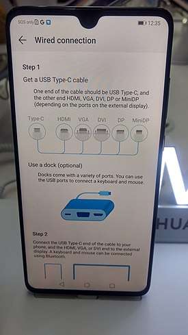
Currently, DisplayPort is the most widely implemented alternate mode, and is used to provide video output on devices that do not have standard-size DisplayPort or HDMI ports, such as smartphones and laptops. A USB-C multiport adapter converts the device's native video stream to DisplayPort/HDMI/VGA, allowing it to be displayed on an external display, such as a television set or computer monitor.
It is also used on USB-C docks designed to connect a device to a power source, external display, USB hub, and optional extra (such as a network port) with a single cable. These functions are sometimes implemented directly into the display instead of a separate dock[67], meaning a user connects their device to the display via USB-C with no other connections required.
Examples of devices that support DisplayPort Alternate Mode over USB-C include: MacBook, Chromebook Pixel, Surface Book 2, Samsung Galaxy TabPro S/Tab S4, iPad Pro (3rd generation), BlackBerry Key2, Essential Phone, HTC 10/U Ultra/U11/U12+, Huawei Mate 10/20/30, LG V20/V30/V40*/V50, OnePlus 7/7T, Razer Phone, ROG Phone/II, Samsung Galaxy S8/S9/S10, Sony Xperia 1/5, Microsoft Lumia 950, HP Elite x3 etc.[68][69][70]
High-power charging
Examples of devices that support high-power charging according to the USB Power Delivery specification include: MacBook, Chromebook Pixel, Surface Book 2, Dell Venue 10 Pro, Lenovo ThinkPad X1, Samsung Galaxy TabPro S, Samsung Galaxy Tab S4, iPad Pro, Nintendo Switch, Nexus 5X/6P, Google Pixel/2/3/4, ROG Phone, BlackBerry Key2, Essential Phone, HTC 10/U Ultra, LG G5/G6, Moto Z, Nokia 8, Razer Phone, Samsung Galaxy S8/S9, Samsung Galaxy Note 8/Note 9,Sony Xperia XZ1/XZ2, Apple iPhone 8/X etc.
Compatibility issues
Power issues with cables
Many cables claiming to support USB-C are actually not compliant to the standard. Using these cables would have a potential consequence of damaging devices that they are connected to.[71][72][73] There are reported cases of laptops being destroyed due to the use of non-compliant cables.[74]
Some non-compliant cables with a USB-C connector on one end and a legacy USB-A plug or Micro-B receptacle on the other end incorrectly terminate the Configuration Channel (CC) with a 10kΩ pullup to VBUS instead of the specification mandated 56 kΩ pullup,[75] causing a device connected to the cable to incorrectly determine the amount of power it is permitted to draw from the cable. Cables with this issue may not work properly with certain products, including Apple and Google products, and may even damage power sources such as chargers, hubs, or PC USB ports.[76][77]
When a defective USB-C cable or power source is used, the voltage seen by a USB-C device can be different from the voltage expected by the device. This may result in an overvoltage on the VBUS pin. Also due to the fine pitch of the USB-C receptacle, the VBUS pin from the cable may contact with the CC pin of the USB-C receptacle resulting in a short-to-VBUS electrical issue due to the fact that the VBUS pin is rated up to 20V while the CC pins are rated up to 5.5V. To overcome these issues, USB Type-C port protection must be used between USB-C connector and USB-C Power Delivery controller.[78]
Compatibility with audio adapters
On devices that have omitted the 3.5 mm audio jack, the USB-C port can be used to connect wired accessories such as headphones.
There are primarily two types of USB-C adapters (active adapters with DACs, passive adapters without DACs) and two modes of audio output from devices (phones without onboard DACs that send out digital audio, phones with onboard DACs that send out analog audio).[79][80]
When an active set of USB-C headphones or adapter is used, digital audio is sent through the USB-C port. The conversion by the DAC and amplifier is done inside of the headphones or adapter, instead of on the phone. The sound quality is dependent on the headphones/adapter's DAC. Active adapters with a built-in DAC have near-universal support for devices that output digital and analog audio, adhering to the Audio Device Class 3.0 and Audio Adapter Accessory Mode specifications.
Examples of such active adapters include external USB sound cards/DACs that do not require special drivers,[81] and USB-C to 3.5 mm headphone jack adapters by Apple, Google, Essential, Razer, HTC.[82]
On the other hand, when a passive set of USB-C headphones or adapter is used, analog audio is sent through the USB-C port. The conversion by the DAC and amplifier is done on the phone; the headphones or adapter simply passthrough the signal. The sound quality is dependent on the phone's onboard DAC. Passive adapters without a built-in DAC are only compatible with devices that output analog audio, adhering to the Audio Adapter Accessory Mode specification.
| Supported mode | Specification | Devices | USB-C adapters with DACs (active adapters) | USB-C adapters without DACs (passive adapters) |
|---|---|---|---|---|
| Digital audio output | Audio Device Class 3.0 (digital audio) | Google Pixel 2, HTC U11, Essential Phone, Razer Phone etc. |
✓ Digital-to-analog conversion by adapter |
✗ Incompatible (conversion required) |
| Analog audio output | Audio Device Class 3.0 (digital audio) Audio Adapter Accessory Mode (analog audio) |
Moto Z2 Force, Sony Xperia XZ2, Huawei P20 Pro, LeEco, Xiaomi phones etc. |
✓ Digital-to-analog conversion by adapter |
✓ Analog passthrough (no conversion) |
Compatibility with other fast charging technology
In 2016, Benson Leung, an engineer at Google, pointed out that Quick Charge 2.0 and 3.0 technologies developed by Qualcomm are not compatible with the USB-C standard.[83] Qualcomm responded that it is possible to make fast charge solutions fit the voltage demands of USB-C and that there are no reports of problems; however, it did not address the standard compliance issue at that time.[84] Later in the year, Qualcomm released Quick Charge 4 technology, which cited – as an advancement over previous generations – "USB Type-C and USB PD compliant".[85]
See also
- Thunderbolt 3
- USB hardware#Host and device interface receptacles
References
- Universal Serial Bus Type-C Cable and Connector Specification Revision 1.3 (14 July 2017), Revision History, page 14.
- Hruska, Joel (13 March 2015). "USB-C vs. USB 3.1: What's the difference?". ExtremeTech. Retrieved 9 April 2015.
- Howse, Brett (12 August 2014). "USB Type-C Connector Specifications Finalized". Retrieved 28 December 2014.
- "IEC - News > News log 2016". www.iec.ch.
- "USB Type-C Cable and Connector : Language Usage Guidelines from USB-IF" (PDF). Usb.org. Retrieved 15 December 2018.
- "USB Type-C Overview" (PDF). usb.org. USB-IF. 20 October 2016. Archived from the original (PDF) on 20 December 2016.
- Ngo, Dong. "USB Type-C: One cable to connect them all". CNET. Retrieved 18 June 2015.
- "USB Type-C® Cable and Connector Specification". USB Implementers Forum, Inc. Retrieved 19 December 2019.
- Universal Serial Bus Type-C Cable and Connector Specification Revision 1.2 (25 March 2016), table 3–1, page 27.
- "USB 3.0 Promoter Group Announces USB Type-C Connector Ready for Production" (PDF). 12 August 2014.
- "USB Power Delivery" (PDF). usb.org. USB-IF. 20 October 2016. Archived from the original (PDF) on 16 August 2017. Retrieved 3 January 2018.
- "USB Compliance and Certification" (PDF). usb.org. USB-IF. 20 October 2016. Archived from the original (PDF) on 20 December 2016.
- "Transition existing products from USB 2.0 OTG to USB Type-C" (PDF).
- Universal Serial Bus Type-C Cable and Connector Specification Revision 1.1 (3 April 2015), section 2.2, page 20.
- Universal Serial Bus Type-C Cable and Connector Specification Release 1.3 (14 July 2017), section A.1, page 213.
- "USB Type-C Specification Release 1.1" (PDF). GitHub. 13 July 2015.
- "USB Type-C Connectors and Cable Assemblies Compliance Document, v1.2 | USB-IF". usb.org.
- "USB Type-C(TM) Cable and Connector Specification Revision 1.4, March 29, 2019" (PDF).
- "Universal Serial Bus Type-C Cable and Connector Specification, September 21, 2019" (PDF).
- "IEC 62680-1-3:2016 | IEC Webstore | energy, multimedia, cable, USB, LVDC". webstore.iec.ch.
- "IEC 62680-1-3:2017 | IEC Webstore | energy, multimedia, cable, USB, LVDC". webstore.iec.ch.
- "IEC 62680-1-3:2018 | IEC Webstore | energy, multimedia, cable, USB, LVDC". webstore.iec.ch.
- "USB Type-C(TM) Locking Connector Specification | USB-IF". www.usb.org.
- "USB Type-C(TM) Port Controller Interface Specification | USB-IF". www.usb.org.
- "IEC 62680-1-4:2018 | IEC Webstore". webstore.iec.ch.
- Shilov, Anton. "USB-IF Publishes Audio over USB Type-C Specifications".
- Universal Serial Bus Type-C Cable and Connector Specification Release 1.3 (14 July 2017), section 4.5.2, page 144.
- Cunningham, Andrew (9 January 2015). "USB 3.1 and Type-C: The only stuff at CES that everyone is going to use | Ars Technica UK". ArsTechnica.co.uk. Retrieved 18 June 2015.
- "VESA® Brings DisplayPort™ to New USB Type-C Connector". DisplayPort. 22 September 2014. Retrieved 18 June 2015.
- "DisplayPort Alternate Mode on USB-C - Technical Overview" (PDF). usb.org. USB-IF. 20 October 2016. Archived from the original (PDF) on 20 December 2016.
- "MHL® – Expand Your World". MHLTech.org. Retrieved 18 June 2015.
- "MHL Alternate Mode reference design for superMHL over USB Type-C". AnandTech.com. 15 March 2016. Retrieved 18 June 2015.
- "MHL Releases Alternate Mode for New USB Type-C Connector". MHLTech.org. MHLTech.org. 17 November 2014. Retrieved 18 June 2015.
- "MHL Alternate Mode over USB Type-C to support superMHL". www.mhltech.org. www.mhltech.org. 6 January 2015. Retrieved 15 November 2016.
- "MHL Alt Mode: Optimizing Consumer Video Transmission" (PDF). usb.org. MHL, LLC. 18 November 2015. Archived from the original (PDF) on 14 September 2016.
- "Thunderbolt 3 – The USB-C That Does It All | Thunderbolt Technology Community". Thunderbolttechnology.net. Retrieved 18 June 2015.
- "One port to rule them all: Thunderbolt 3 and USB Type-C join forces". Retrieved 2 June 2015.
- "Thunderbolt 3 is twice as fast and uses reversible USB-C". Retrieved 2 June 2015.
- Anthony, Sebastian (2 June 2015). "Thunderbolt 3 embraces USB Type-C connector, doubles bandwidth to 40Gbps". Ars Technica UK.
- "HDMI Press Release: HDMI Releases Alternate Mode for USB Type-C™ Connector". hdmi.org.
- "HDMI LLC - HDMI Over USB Type-C" (PDF). usb.org. HDMI LLC. 20 October 2016. Archived from the original (PDF) on 18 February 2017.
- "HDMI Alt Mode for USB Type-C Announced". anandtech.com.
- "A new standard will allow your USB-C devices to connect to HDMI". neowin.net.
- "HDMI Alt Mode for USB Type-C™ Connector". hdmi.org.
- "New Open Industry Standard Introduced for Connecting Next-Generation VR Headsets to PCs, Other Devices". GlobeNewswire News Room. 17 July 2018.
- Smith, Ryan (17 July 2018). "VirtualLink USB-C Alt Mode Announced: Standardized Connector for VR Headsets". AnandTech. Retrieved 21 August 2018.
- "[802.3_DIALOG] USB-C Ethernet Alternate Mode". ieee. 26 March 2015.
- "TECHNOLOGY BRIEF Thunderbolt™ 3" (PDF). 21 September 2018.
- "Node Pro". 21 September 2018.
- "USB Logo Usage Guidelines" (PDF). usb.org. USB-IF. 11 March 2016. Archived from the original (PDF) on 20 December 2016.
- "CalDigit USB-C Cable". 21 September 2018.
- "VESA® Brings DisplayPort™ to New USB Type-C Connector | VESA". www.vesa.org. Retrieved 11 December 2016.
- Termination Resistors Required for the USB Type-C Connector – KBA97180
- Universal Serial Bus Type-C Cable and Connector Specification Revision 1.3 (14 July 2017), section 2.4, page 26.
- Universal Serial Bus Type-C Cable and Connector Specification Revision 1.3 (14 July 2017), section 5.1.2, page 203.
- Universal Serial Bus Type-C Cable and Connector Specification Revision 1.3 (14 July 2017), section A, page 213.
- "Android – Marshmallow". Retrieved 12 October 2015.
- "Charge your Chromebook Pixel (2015)". Retrieved 31 October 2015.
- "FreeBSD 8.2 Release Notes". www.freebsd.org. 22 April 2011. Retrieved 5 February 2018.
- "NetBSD 7.2 Released". Retrieved 14 January 2019.
- "OpenBSD 5.7". Retrieved 27 June 2019.
- "Using the USB-C port and adapters on your MacBook (Retina, 12-inch, Early 2015) - Apple Support". Support.Apple.com. 28 May 2015. Retrieved 18 June 2015.
- Microsoft. "Update for USB Type-C billboard support and Kingston thumb drive is enumerated incorrectly in Windows". Retrieved 8 December 2015.
- Microsoft. "Windows support for USB Type-C connectors". Microsoft MSDN. Retrieved 30 September 2015.
- "USB Dual Role Driver Stack Architecture - Windows drivers". docs.microsoft.com.
- Burke, Steve (25 March 2019). "Why USB 3.1 Type-C Isn't on More Cases & Cable Factory Tour in Dongguan, China". Gamers Nexus. Retrieved 26 June 2019.
- "DisplayPort over USB-C". DisplayPort.
- "DisplayPort USB Özelliğine Sahip Telefonlar - Epey". www.epey.com.
- "Search | Device Specs | PhoneDB - The Largest Phone Specs Database". phonedb.net.
- "SlimPort". www.slimportconnect.com.
- Mills, Chris. "A Google Engineer Is Publicly Shaming Crappy USB-C Cables".
- Opam, Kwame (5 November 2015). "A Google engineer is testing USB Type-C cables so you don't have to". The Verge.
- "Be careful about which USB-C cables you buy off the Internet". TechnoBuffalo. 16 November 2015.
- Bohn, Dieter (4 February 2016). "Laptops are getting destroyed by cheap USB-C cables". The Verge.
- Universal Serial Bus Type-C Cable and Connector Specification Revision 1.1 (3 April 2015), page 60, table 3–13, note 1.
- Kif Leswing (5 November 2015). "Google Engineer Reviews Defective USB Cables on Amazon - Fortune". Fortune.
- "In response to the Type-C cable discussions". OnePlus Community.
- "TCPP01-M12 Type-C Port Protection" (PDF).
- "USB-C audio: Everything you need to know". Android Central. 2 May 2018.
- "Bring back the headphone jack: Why USB-C audio still doesn't work". PCWorld. 10 September 2018.
- T, Nick. "Android 5.0 Lollipop supports USB DAC audio devices, we go ears-on". Phone Arena.
- Schoon, Ben (1 November 2018). "Hands-on: Apple's new USB-C headphone adapter is your cheapest option for analog audio on Pixel".
- "Google engineer warns USB-C, Qualcomm Quick Charge are incompatible - ExtremeTech". 25 April 2016.
- "Qualcomm says it's fine to fast-charge your phone over USB-C". Engadget.
- "Qualcomm Quick Charge 4: Five minutes of charging for five hours of battery life". Qualcomm. 17 November 2016.
External links
| Wikimedia Commons has media related to USB-C. |
- The Universal Serial Bus Type-C Cable and Connector Specification is included in a set of USB documents which can be downloaded from USB.org.