American wire gauge
American wire gauge (AWG), also known as the Brown & Sharpe wire gauge, is a logarithmic stepped standardized wire gauge system used since 1857, predominantly in North America, for the diameters of round, solid, nonferrous, electrically conducting wire. Dimensions of the wires are given in ASTM standard B 258.[1] The cross-sectional area of each gauge is an important factor for determining its current-carrying ampacity.
Increasing gauge numbers denote decreasing wire diameters, which is similar to many other non-metric gauging systems such as British Standard Wire Gauge (SWG), but unlike IEC 60228, the metric wire-size standard used in most parts of the world. This gauge system originated in the number of drawing operations used to produce a given gauge of wire. Very fine wire (for example, 30 gauge) required more passes through the drawing dies than 0 gauge wire did. Manufacturers of wire formerly had proprietary wire gauge systems; the development of standardized wire gauges rationalized selection of wire for a particular purpose.
The AWG tables are for a single, solid and round conductor. The AWG of a stranded wire is determined by the cross-sectional area of the equivalent solid conductor. Because there are also small gaps between the strands, a stranded wire will always have a slightly larger overall diameter than a solid wire with the same AWG.
AWG is also commonly used to specify body piercing jewelry sizes (especially smaller sizes), even when the material is not metallic.[2]
Formulae
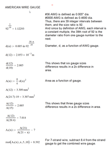
By definition, No. 36 AWG is 0.005 inches in diameter, and No. 0000 is 0.46 inches in diameter. The ratio of these diameters is 1:92, and there are 40 gauge sizes from No. 36 to No. 0000, or 39 steps. Because each successive gauge number increases cross sectional area by a constant multiple, diameters vary geometrically. Any two successive gauges (e.g., A & B ) have diameters in the ratio (dia. B ÷ dia. A) of (approximately 1.12293), while for gauges two steps apart (e.g., A, B, & C), the ratio of the C to A is about 1.122932 = 1.26098. The diameter of a No. n AWG wire is determined, for gauges smaller than 00 (36 to 0), according to the following formula:


(see below for gauges larger than No. 0 (i.e., No. 00, No. 000, No. 0000 ).)
or equivalently:

The gauge can be calculated from the diameter using [3]

and the cross-section area is
- ,

The standard ASTM B258 - 02(2008) Standard Specification for Standard Nominal Diameters and Cross-Sectional Areas of AWG Sizes of Solid Round Wires Used as Electrical Conductors defines the ratio between successive sizes to be the 39th root of 92, or approximately 1.1229322.[4] ASTM B 258-02 also dictates that wire diameters should be tabulated with no more than 4 significant figures, with a resolution of no more than 0.0001 inches (0.1 mils) for wires larger than No. 44 AWG, and 0.00001 inches (0.01 mils) for wires No. 45 AWG and smaller.
Sizes with multiple zeros are successively larger than No. 0 and can be denoted using "number of zeros/0", for example 4/0 for 0000. For an m/0 AWG wire, use n = −(m − 1) = 1 − m in the above formulas. For instance, for No. 0000 or 4/0, use n = −3.
Rules of thumb
The sixth power of 39√92 is very close to 2,[5] which leads to the following rules of thumb:
- When the cross-sectional area of a wire is doubled, the AWG will decrease by 3. (E.g. two No. 14 AWG wires have about the same cross-sectional area as a single No. 11 AWG wire.) This doubles the conductance.
- When the diameter of a wire is doubled, the AWG will decrease by 6. (E.g. No. 2 AWG is about twice the diameter of No. 8 AWG.) This quadruples the cross-sectional area and the conductance.
- A decrease of ten gauge numbers, for example from No. 12 to No. 2, multiplies the area and weight by approximately 10, and reduces the electrical resistance (and increases the conductance) by a factor of approximately 10.
- For the same cross section, aluminum wire has a conductivity of approximately 61% of copper, so an aluminum wire has nearly the same resistance as a copper wire smaller by 2 AWG sizes, which has 62.9% of the area.
- A solid round 18 AWG wire is about 1 mm in diameter.
- An approximation for the resistance of copper wire may be expressed as follows:
Approximate resistance of copper wire[6]:27 AWG mΩ/ft mΩ/m AWG mΩ/ft mΩ/m AWG mΩ/ft mΩ/m AWG mΩ/ft mΩ/m 0 0.1 0.32 10 1 3.2 20 10 32 30 100 320 1 0.125 0.4 11 1.25 4 21 12.5 40 31 125 400 2 0.16 0.5 12 1.6 5 22 16 50 32 160 500 3 0.2 0.64 13 2 6.4 23 20 64 33 200 640 4 0.25 0.8 14 2.5 8 24 25 80 34 250 800 5 0.32 1 15 3.2 10 25 32 100 35 320 1000 6 0.4 1.25 16 4 12.5 26 40 125 36 400 1250 7 0.5 1.6 17 5 16 27 50 160 37 500 1600 8 0.64 2 18 6.4 20 28 64 200 38 640 2000 9 0.8 2.5 19 8 25 29 80 250 39 800 2500
Tables of AWG wire sizes
The table below shows various data including both the resistance of the various wire gauges and the allowable current (ampacity) based on a copper conductor with plastic insulation. The diameter information in the table applies to solid wires. Stranded wires are calculated by calculating the equivalent cross sectional copper area. Fusing current (melting wire) is estimated based on 25 °C (77 °F) ambient temperature. The table below assumes DC, or AC frequencies equal to or less than 60 Hz, and does not take skin effect into account. "Turns of wire per unit length" is the reciprocal of the conductor diameter; it is therefore an upper limit for wire wound in the form of a helix (see solenoid), based on uninsulated wire.
| AWG | Diameter | Turns of wire, without insulation | Area | Copper wire | ||||||||||
|---|---|---|---|---|---|---|---|---|---|---|---|---|---|---|
| Resistance/length[7] | Ampacity,[8] at 20 °C insulation material temperature rating, or for single unbundled wires in equipment for 16 AWG and smaller[9] |
Fusing current[10][11] | ||||||||||||
| 60 °C | 75 °C | 90 °C | Preece[12][13][14][15] | Onderdonk[16][15] | ||||||||||
| (in) | (mm) | (per in) | (per cm) | (kcmil) | (mm2) | (mΩ/m[lower-alpha 1]) | (mΩ/ft[lower-alpha 2]) | (A) | ~10 s | 1 s | 32 ms | |||
| 0000 (4/0) | 0.4600[lower-alpha 3] | 11.684[lower-alpha 3] | 2.17 | 0.856 | 212 | 107 | 0.1608 | 0.04901 | 195 | 230 | 260 | 3.2 kA | 33 kA | 182 kA |
| 000 (3/0) | 0.4096 | 10.405 | 2.44 | 0.961 | 168 | 85.0 | 0.2028 | 0.06180 | 165 | 200 | 225 | 2.7 kA | 26 kA | 144 kA |
| 00 (2/0) | 0.3648 | 9.266 | 2.74 | 1.08 | 133 | 67.4 | 0.2557 | 0.07793 | 145 | 175 | 195 | 2.3 kA | 21 kA | 115 kA |
| 0 (1/0) | 0.3249 | 8.251 | 3.08 | 1.21 | 106 | 53.5 | 0.3224 | 0.09827 | 125 | 150 | 170 | 1.9 kA | 16 kA | 91 kA |
| 1 | 0.2893 | 7.348 | 3.46 | 1.36 | 83.7 | 42.4 | 0.4066 | 0.1239 | 110 | 130 | 145 | 1.6 kA | 13 kA | 72 kA |
| 2 | 0.2576 | 6.544 | 3.88 | 1.53 | 66.4 | 33.6 | 0.5127 | 0.1563 | 95 | 115 | 130 | 1.3 kA | 10.2 kA | 57 kA |
| 3 | 0.2294 | 5.827 | 4.36 | 1.72 | 52.6 | 26.7 | 0.6465 | 0.1970 | 85 | 100 | 115 | 1.1 kA | 8.1 kA | 45 kA |
| 4 | 0.2043 | 5.189 | 4.89 | 1.93 | 41.7 | 21.2 | 0.8152 | 0.2485 | 70 | 85 | 95 | 946 A | 6.4 kA | 36 kA |
| 5 | 0.1819 | 4.621 | 5.50 | 2.16 | 33.1 | 16.8 | 1.028 | 0.3133 | 795 A | 5.1 kA | 28 kA | |||
| 6 | 0.1620 | 4.115 | 6.17 | 2.43 | 26.3 | 13.3 | 1.296 | 0.3951 | 55 | 65 | 75 | 668 A | 4.0 kA | 23 kA |
| 7 | 0.1443 | 3.665 | 6.93 | 2.73 | 20.8 | 10.5 | 1.634 | 0.4982 | 561 A | 3.2 kA | 18 kA | |||
| 8 | 0.1285 | 3.264 | 7.78 | 3.06 | 16.5 | 8.37 | 2.061 | 0.6282 | 40 | 50 | 55 | 472 A | 2.5 kA | 14 kA |
| 9 | 0.1144 | 2.906 | 8.74 | 3.44 | 13.1 | 6.63 | 2.599 | 0.7921 | 396 A | 2.0 kA | 11 kA | |||
| 10 | 0.1019 | 2.588 | 9.81 | 3.86 | 10.4 | 5.26 | 3.277 | 0.9989 | 30 | 35 | 40 | 333 A | 1.6 kA | 8.9 kA |
| 11 | 0.0907 | 2.305 | 11.0 | 4.34 | 8.23 | 4.17 | 4.132 | 1.260 | 280 A | 1.3 kA | 7.1 kA | |||
| 12 | 0.0808 | 2.053 | 12.4 | 4.87 | 6.53 | 3.31 | 5.211 | 1.588 | 20 | 25 | 30 | 235 A | 1.0 kA | 5.6 kA |
| 13 | 0.0720 | 1.828 | 13.9 | 5.47 | 5.18 | 2.62 | 6.571 | 2.003 | 198 A | 798 A | 4.5 kA | |||
| 14 | 0.0641 | 1.628 | 15.6 | 6.14 | 4.11 | 2.08 | 8.286 | 2.525 | 15 | 20 | 25 | 166 A | 633 A | 3.5 kA |
| 15 | 0.0571 | 1.450 | 17.5 | 6.90 | 3.26 | 1.65 | 10.45 | 3.184 | 140 A | 502 A | 2.8 kA | |||
| 16 | 0.0508 | 1.291 | 19.7 | 7.75 | 2.58 | 1.31 | 13.17 | 4.016 | 18 | 117 A | 398 A | 2.2 kA | ||
| 17 | 0.0453 | 1.150 | 22.1 | 8.70 | 2.05 | 1.04 | 16.61 | 5.064 | 99 A | 316 A | 1.8 kA | |||
| 18 | 0.0403 | 1.024 | 24.8 | 9.77 | 1.62 | 0.823 | 20.95 | 6.385 | 10 | 14 | 16 | 83 A | 250 A | 1.4 kA |
| 19 | 0.0359 | 0.912 | 27.9 | 11.0 | 1.29 | 0.653 | 26.42 | 8.051 | — | — | — | 70 A | 198 A | 1.1 kA |
| 20 | 0.0320 | 0.812 | 31.3 | 12.3 | 1.02 | 0.518 | 33.31 | 10.15 | 5 | 11 | — | 58.5 A | 158 A | 882 A |
| 21 | 0.0285 | 0.723 | 35.1 | 13.8 | 0.810 | 0.410 | 42.00 | 12.80 | — | — | — | 49 A | 125 A | 700 A |
| 22 | 0.0253 | 0.644 | 39.5 | 15.5 | 0.642 | 0.326 | 52.96 | 16.14 | 3 | 7 | — | 41 A | 99 A | 551 A |
| 23 | 0.0226 | 0.573 | 44.3 | 17.4 | 0.509 | 0.258 | 66.79 | 20.36 | — | — | — | 35 A | 79 A | 440 A |
| 24 | 0.0201 | 0.511 | 49.7 | 19.6 | 0.404 | 0.205 | 84.22 | 25.67 | 2.1 | 3.5 | — | 29 A | 62 A | 348 A |
| 25 | 0.0179 | 0.455 | 55.9 | 22.0 | 0.320 | 0.162 | 106.2 | 32.37 | — | — | — | 24 A | 49 A | 276 A |
| 26 | 0.0159 | 0.405 | 62.7 | 24.7 | 0.254 | 0.129 | 133.9 | 40.81 | 1.3 | 2.2 | — | 20 A | 39 A | 218 A |
| 27 | 0.0142 | 0.361 | 70.4 | 27.7 | 0.202 | 0.102 | 168.9 | 51.47 | — | — | — | 17 A | 31 A | 174 A |
| 28 | 0.0126 | 0.321 | 79.1 | 31.1 | 0.160 | 0.0810 | 212.9 | 64.90 | 0.83 | 1.4 | — | 14 A | 24 A | 137 A |
| 29 | 0.0113 | 0.286 | 88.8 | 35.0 | 0.127 | 0.0642 | 268.5 | 81.84 | — | — | — | 12 A | 20 A | 110 A |
| 30 | 0.0100 | 0.255 | 99.7 | 39.3 | 0.101 | 0.0509 | 338.6 | 103.2 | 0.52 | 0.86 | — | 10 A | 15 A | 86 A |
| 31 | 0.00893 | 0.227 | 112 | 44.1 | 0.0797 | 0.0404 | 426.9 | 130.1 | — | — | — | 9 A | 12 A | 69 A |
| 32 | 0.00795 | 0.202 | 126 | 49.5 | 0.0632 | 0.0320 | 538.3 | 164.1 | 0.32 | 0.53 | — | 7 A | 10 A | 54 A |
| 33 | 0.00708 | 0.180 | 141 | 55.6 | 0.0501 | 0.0254 | 678.8 | 206.9 | — | — | — | 6 A | 7.7 A | 43 A |
| 34 | 0.00630 | 0.160 | 159 | 62.4 | 0.0398 | 0.0201 | 856.0 | 260.9 | 0.18 | 0.3 | — | 5 A | 6.1 A | 34 A |
| 35 | 0.00561 | 0.143 | 178 | 70.1 | 0.0315 | 0.0160 | 1079 | 329.0 | — | — | — | 4 A | 4.8 A | 27 A |
| 36 | 0.00500[lower-alpha 3] | 0.127[lower-alpha 3] | 200 | 78.7 | 0.0250 | 0.0127 | 1361 | 414.8 | — | — | — | 4 A | 3.9 A | 22 A |
| 37 | 0.00445 | 0.113 | 225 | 88.4 | 0.0198 | 0.0100 | 1716 | 523.1 | — | — | — | 3 A | 3.1 A | 17 A |
| 38 | 0.00397 | 0.101 | 252 | 99.3 | 0.0157 | 0.00797 | 2164 | 659.6 | — | — | — | 3 A | 2.4 A | 14 A |
| 39 | 0.00353 | 0.0897 | 283 | 111 | 0.0125 | 0.00632 | 2729 | 831.8 | — | — | — | 2 A | 1.9 A | 11 A |
| 40 | 0.00314 | 0.0799 | 318 | 125 | 0.00989 | 0.00501 | 3441 | 1049 | — | — | — | 1 A | 1.5 A | 8.5 A |
- or, equivalently, Ω/km
- or, equivalently, Ω/kft
- Exactly, by definition
In the North American electrical industry, conductors larger than 4/0 AWG are generally identified by the area in thousands of circular mils (kcmil), where 1 kcmil = 0.5067 mm2. The next wire size larger than 4/0 has a cross section of 250 kcmil. A circular mil is the area of a wire one mil in diameter. One million circular mils is the area of a circle with 1000 mil (1 inch) diameter. An older abbreviation for one thousand circular mils is MCM.
Stranded wire AWG sizes
AWG gauges are also used to describe stranded wire. The AWG gauge of a stranded wire represents the sum of the cross-sectional areas of the individual strands; the gaps between strands are not counted. When made with circular strands, these gaps occupy about 25% of the wire area, thus requiring the overall bundle diameter to be about 13% larger than a solid wire of equal gauge.
Stranded wires are specified with three numbers, the overall AWG size, the number of strands, and the AWG size of a strand. The number of strands and the AWG of a strand are separated by a slash. For example, a 22 AWG 7/30 stranded wire is a 22 AWG wire made from seven strands of 30 AWG wire.
As indicated in the Formulas and Rules of Thumb sections above, differences in AWG translate directly into ratios of diameter or area. This property can be employed to easily find the AWG of a stranded bundle by measuring the diameter and count of its strands. (This only applies to bundles with circular strands of identical size.) To find the AWG of 7-strand wire with equal strands, subtract 8.4 from the AWG of a strand. Similarly, for 19-strand subtract 12.7, and for 37 subtract 15.6. See the Mathcad worksheet illustration of this straightforward application of the formula.
Measuring strand diameter is often easier and more accurate than attempting to measure bundle diameter and packing ratio. Such measurement can be done with a wire gauge go-no-go tool such as a Starrett 281 or Mitutoyo 950-202, or with a caliper or micrometer.
Nomenclature and abbreviations in electrical distribution
Alternative ways are commonly used in the electrical industry to specify wire sizes as AWG.
- 4 AWG (proper)
- #4 (the number sign is used as an abbreviation for “number”)
- No. 4 (No. is used as an abbreviation for “number”)
- No. 4 AWG
- 4 ga. (abbreviation for “gauge”)
- 000 AWG (proper for large sizes)
- 3/0 (common for large sizes) Pronounced "three-aught"
- 3/0 AWG
- #000
The industry also bundles common wire for use in mains electricity distribution in homes and businesses, identifying a bundle's wire size followed by the number of wires in the bundle.
- #14/2 (also written “14-2”) is a nonmetallic (NM) sheathed bundle (-B) of three solid 14 AWG wires having a bare ground in the middle of two insulated conductors. The insulation surrounding the two conductors is white and black, for neutral and “hot” (electrified) respectively. This sheath for 14 AWG cable is usually white when used for NM-B wiring intended for electrical distribution in a dry location, although older wire may be black. #14 wire is used mainly in lighting circuits with a 15-ampere circuit breaker.
- #12/2 is a nonmetallic sheathed bundle of three solid 12 AWG wires having a bare ground in the middle of two insulated conductors in a flat-shaped NM-B yellow-colored sheath. The color is a North American industry standard for cables made since 2003, and aids identification. It is always used for countertop appliance outlets in kitchens, and often for outlets in bathrooms (for high-wattage hair dryers) and other rooms.
- #10/3 with ground (also written “10-3 w/gnd”) is a nonmetallic sheathed bundle of four solid 10 AWG wires having a bare ground and three insulated conductors twisted into a round-shaped NM-B orange-colored sheath. The insulated conductors are black, white, and red, usually supplying both 120 and 240 volts for clothes dryers. Some cables of this type may be flat to save copper.
- #8 and larger cables are now insulated in black, with 6/3 for 50-amp electric ranges in kitchens, and 0/2 (two black-insulated #0 AWG wires, plus ground) for the main 200-amp cable from the weatherhead and electricity meter to the main breaker panel.
14/3 and 12/3 cables are also available, used mainly between three-way (two-location) switches, and to have separate wall controls for ceiling fans and their attached light fixtures, or to have one half of a duplex outlet switched and the other always on.
12/2 and 14/2 can also be used for the rare 240-volt-only 15- or 20-amp plug by clearly marking the white wire red or black, since there is no neutral wire. Two conductor cable is available with black and red conductors only for this purpose; the outer sheath is likewise red.
277/480-volt cable is identical to 120/240, except that neutral is grey and hot is yellow (plus an optional orange, used as the red is). The higher voltage, used only in large non-residential buildings, allows more than twice as much electrical power (in watts) to be drawn through the same gauge of wire.
UF-B cable is “underground feeder” cable, which regardless of wire gauge has a solid waterproof grey sheath completely surrounding and filling the space between the conductors, which still have their individual colors. Other types of armored or metallic cable (types AC and MC) have an aluminum casing that may be used as a ground conductor, for which it is not necessary to calculate an equivalent wire gauge.
All new cables are marked as being “with ground” or “w/gnd”, since installation of ungrounded cables has been prohibited by electrical codes for decades. The ground wire is typically the same gauge as the others, despite not being intended to carry large amounts of current for more than a few seconds in the event of a short circuit.
Pronunciation
AWG is colloquially referred to as gauge and the zeros in large wire sizes are referred to as aught /ˈɔːt/. Wire sized 1 AWG is referred to as "one gauge" or "No. 1" wire; similarly, smaller diameters are pronounced "x gauge" or "No. X" wire, where x is the positive integer AWG number. Consecutive AWG wire sizes larger than No. 1 wire are designated by the number of zeros:
- No. 0, typically written 1/0 and is referred to as "one aught" wire
- No. 00, typically written 2/0 and is referred to as "two aught" wire
- No. 000, typically written 3/0 and is referred to as "three aught" wire,
and so on.
See also
- Wire gauge comparison chart
- IEC 60228, the metric wire-size standard used in most parts of the world.
- Brown & Sharpe
- Circular mil, Electrical industry standard for wires larger than 4/0.
- Standard Wire Gauge (SWG), the British imperial standard BS3737, superseded by the metric.
- Stubs Iron Wire Gauge
- Jewelry wire gauge
- Body jewelry sizes
- Electrical wiring
- Number 8 wire, a term used in the New Zealand vernacular
References
- "ASTM B258 - 14 Standard Specification for Standard Nominal Diameters and Cross-Sectional Areas of AWG Sizes of Solid Round Wires Used as Electrical Conductors". West Conshohocken: ASTM International. Archived from the original on 22 July 2014. Retrieved 22 March 2015.(subscription required)
- SteelNavel.com Body Piercing Jewelry Size Reference — illustrating the different ways that size is measured on different kinds of jewelry
- The logarithm to the base 92 can be computed using any other logarithm, such as common or natural logarithm, using log92x = (log x)/(log 92).
- ASTM Standard B 258-02, page 4
- The result is roughly 2.0050, or one-quarter of one percent higher than 2
- Copper Wire Tables (Technical report). Circular of the Bureau of Standards No.31 (3d ed.). United States Department of Commerce. October 1, 1914.
-
Figure for solid copper wire at 68 °F, (Not in accordance to NEC Codebook 2014 Ch. 9, Table 8) computed based on 100% IACS conductivity of 58.0 MS/m, which agrees with multiple sources:
- Mark Lund, PowerStream Inc., American Wire Gauge table and AWG Electrical Current Load Limits, retrieved 2008-05-02 (although the ft/m conversion seems slightly erroneous)
- Belden Master Catalog, 2006, although data from there for gauges 35 and 37–40 seems obviously wrong.
- NFPA 70 National Electrical Code 2014 Edition Archived 2008-10-15 at the Wayback Machine. Table 310.15(B)(16) (formerly Table 310.16) page 70-161, "Allowable ampacities of insulated conductors rated 0 through 2000 volts, 60°C through 90°C, not more than three current-carrying conductors in raceway, cable, or earth (directly buried) based on ambient temperature of 30°C." Extracts from NFPA 70 do not represent the full position of NFPA and the original complete Code must be consulted. In particular, the maximum permissible overcurrent protection devices may set a lower limit.
- Reference Data for Engineers: Radio, Electronics, Computer and Communications 7th Ed Table 11 "Recommended Current Ratings (Continuous Duty) for electronic equipment and chassis wiring" page 49-16
- Computed using equations from H. Wayne Beaty; Donald G. Fink, eds. (2007), The Standard Handbook for Electrical Engineers (15th ed.), McGraw Hill, pp. 4–25, ISBN 978-0-07-144146-9
- Douglas Brooks (December 1998), "Fusing Current: When Traces Melt Without a Trace" (PDF), Printed Circuit Design, 15 (12): 53
- W. H. Preece (1883), "On the Heating Effects of Electric Currents", Proceedings of the Royal Society (36): 464–471
- W. H. Preece (1887), "On the Heating Effects of Electric Currents", Proceedings of the Royal Society, II (43): 280–295
- W. H. Preece (1888), "On the Heating Effects of Electric Currents", Proceedings of the Royal Society, III (44): 109–111
- Douglas G, Brooks; Johannes Adam (29 June 2015), "Who Were Preece and Onderdonk?", Printed Circuit Design and Fab
- E. R. Stauffacher (June 1928), "Short-time Current Carrying Capacity of Copper Wire" (PDF), General Electric Review, 31 (6)
Further reading
- Donald G. Fink and H. Wayne Beaty, Standard Handbook for Electrical Engineers, Eleventh Edition,McGraw-Hill, New York, 1978, ISBN 0-07-020974-X, page 4-18 and table 4-11.
- File:Gauge Chart.pdf
- How to use a Brown and Sharpe wire gauge.