Fracture mechanics
Fracture mechanics is the field of mechanics concerned with the study of the propagation of cracks in materials. It uses methods of analytical solid mechanics to calculate the driving force on a crack and those of experimental solid mechanics to characterize the material's resistance to fracture.

| Part of a series on | |||||||
| Continuum mechanics | |||||||
|---|---|---|---|---|---|---|---|
|
Laws
|
|||||||
|
|||||||
In modern materials science, fracture mechanics is an important tool used to improve the performance of mechanical components. It applies the physics of stress and strain behavior of materials, in particular the theories of elasticity and plasticity, to the microscopic crystallographic defects found in real materials in order to predict the macroscopic mechanical behavior of those bodies. Fractography is widely used with fracture mechanics to understand the causes of failures and also verify the theoretical failure predictions with real life failures. The prediction of crack growth is at the heart of the damage tolerance mechanical design discipline.
There are three ways of applying a force to enable a crack to propagate:
- Mode I – Opening mode (a tensile stress normal to the plane of the crack),
- Mode II – Sliding mode (a shear stress acting parallel to the plane of the crack and perpendicular to the crack front), and
- Mode III – Tearing mode (a shear stress acting parallel to the plane of the crack and parallel to the crack front).
Motivation
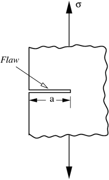
The processes of material manufacture, processing, machining, and forming may introduce flaws in a finished mechanical component. Arising from the manufacturing process, interior and surface flaws are found in all metal structures. Not all such flaws are unstable under service conditions. Fracture mechanics is the analysis of flaws to discover those that are safe (that is, do not grow) and those that are liable to propagate as cracks and so cause failure of the flawed structure. Despite these inherent flaws, it is possible to achieve through damage tolerance analysis the safe operation of a structure. Fracture mechanics as a subject for critical study has barely been around for a century and thus is relatively new.[1][2]
Fracture mechanics should attempt to provide quantitative answers to the following questions:[2]
- What is the strength of the component as a function of crack size?
- What crack size can be tolerated under service loading, i.e. what is the maximum permissible crack size?
- How long does it take for a crack to grow from a certain initial size, for example the minimum detectable crack size, to the maximum permissible crack size?
- What is the service life of a structure when a certain pre-existing flaw size (e.g. a manufacturing defect) is assumed to exist?
- During the period available for crack detection how often should the structure be inspected for cracks?
Linear elastic fracture mechanics
Griffith's criterion

Fracture mechanics was developed during World War I by English aeronautical engineer A. A. Griffith – thus the term Griffith crack – to explain the failure of brittle materials.[3] Griffith's work was motivated by two contradictory facts:
- The stress needed to fracture bulk glass is around 100 MPa (15,000 psi).
- The theoretical stress needed for breaking atomic bonds of glass is approximately 10,000 MPa (1,500,000 psi).
A theory was needed to reconcile these conflicting observations. Also, experiments on glass fibers that Griffith himself conducted suggested that the fracture stress increases as the fiber diameter decreases. Hence the uniaxial tensile strength, which had been used extensively to predict material failure before Griffith, could not be a specimen-independent material property. Griffith suggested that the low fracture strength observed in experiments, as well as the size-dependence of strength, was due to the presence of microscopic flaws in the bulk material.
To verify the flaw hypothesis, Griffith introduced an artificial flaw in his experimental glass specimens. The artificial flaw was in the form of a surface crack which was much larger than other flaws in a specimen. The experiments showed that the product of the square root of the flaw length () and the stress at fracture () was nearly constant, which is expressed by the equation:


An explanation of this relation in terms of linear elasticity theory is problematic. Linear elasticity theory predicts that stress (and hence the strain) at the tip of a sharp flaw in a linear elastic material is infinite. To avoid that problem, Griffith developed a thermodynamic approach to explain the relation that he observed.
The growth of a crack, the extension of the surfaces on either side of the crack, requires an increase in the surface energy. Griffith found an expression for the constant in terms of the surface energy of the crack by solving the elasticity problem of a finite crack in an elastic plate. Briefly, the approach was:

- Compute the potential energy stored in a perfect specimen under a uniaxial tensile load.
- Fix the boundary so that the applied load does no work and then introduce a crack into the specimen. The crack relaxes the stress and hence reduces the elastic energy near the crack faces. On the other hand, the crack increases the total surface energy of the specimen.
- Compute the change in the free energy (surface energy − elastic energy) as a function of the crack length. Failure occurs when the free energy attains a peak value at a critical crack length, beyond which the free energy decreases as the crack length increases, i.e. by causing fracture. Using this procedure, Griffith found that

where is the Young's modulus of the material and is the surface energy density of the material. Assuming and gives excellent agreement of Griffith's predicted fracture stress with experimental results for glass.


Griffith's criterion has been used by Johnson, Kendall and Roberts also in application to adhesive contacts.[4] Recently, it was shown that direct application of the Griffith criterion to a single numerical "cell" leads to a very robust formulation of the Boundary Element Method.[5]
For materials highly deformed before crack propagation, the linear elastic fracture mechanics formulation is no longer applicable and an adapted model is necessary to describe the stress and displacement field close to crack tip, such as on fracture of soft materials.
Irwin's modification

Griffith's work was largely ignored by the engineering community until the early 1950s. The reasons for this appear to be (a) in the actual structural materials the level of energy needed to cause fracture is orders of magnitude higher than the corresponding surface energy, and (b) in structural materials there are always some inelastic deformations around the crack front that would make the assumption of linear elastic medium with infinite stresses at the crack tip highly unrealistic. [6]
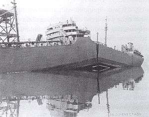
Griffith's theory provides excellent agreement with experimental data for brittle materials such as glass. For ductile materials such as steel, although the relation still holds, the surface energy (γ) predicted by Griffith's theory is usually unrealistically high. A group working under G. R. Irwin[7] at the U.S. Naval Research Laboratory (NRL) during World War II realized that plasticity must play a significant role in the fracture of ductile materials.

In ductile materials (and even in materials that appear to be brittle[8]), a plastic zone develops at the tip of the crack. As the applied load increases, the plastic zone increases in size until the crack grows and the elastically strained material behind the crack tip unloads. The plastic loading and unloading cycle near the crack tip leads to the dissipation of energy as heat. Hence, a dissipative term has to be added to the energy balance relation devised by Griffith for brittle materials. In physical terms, additional energy is needed for crack growth in ductile materials as compared to brittle materials.
Irwin's strategy was to partition the energy into two parts:
- the stored elastic strain energy which is released as a crack grows. This is the thermodynamic driving force for fracture.
- the dissipated energy which includes plastic dissipation and the surface energy (and any other dissipative forces that may be at work). The dissipated energy provides the thermodynamic resistance to fracture. Then the total energy is

where is the surface energy and is the plastic dissipation (and dissipation from other sources) per unit area of crack growth.

The modified version of Griffith's energy criterion can then be written as

For brittle materials such as glass, the surface energy term dominates and . For ductile materials such as steel, the plastic dissipation term dominates and . For polymers close to the glass transition temperature, we have intermediate values of between 2 and 1000 .


Stress intensity factor
Another significant achievement of Irwin and his colleagues was to find a method of calculating the amount of energy available for fracture in terms of the asymptotic stress and displacement fields around a crack front in a linear elastic solid.[7] This asymptotic expression for the stress field in mode I loading is related to the stress intensity factor KI following:[9]

where σij are the Cauchy stresses, r is the distance from the crack tip, θ is the angle with respect to the plane of the crack, and fij are functions that depend on the crack geometry and loading conditions. Irwin called the quantity K the stress intensity factor. Since the quantity fij is dimensionless, the stress intensity factor can be expressed in units of .

When a rigid line inclusion is considered, a similar asymptotic expression for the stress fields is obtained.
Strain energy release
Irwin was the first to observe that if the size of the plastic zone around a crack is small compared to the size of the crack, the energy required to grow the crack will not be critically dependent on the state of stress (the plastic zone) at the crack tip.[6] In other words, a purely elastic solution may be used to calculate the amount of energy available for fracture.
The energy release rate for crack growth or strain energy release rate may then be calculated as the change in elastic strain energy per unit area of crack growth, i.e.,

where U is the elastic energy of the system and a is the crack length. Either the load P or the displacement u are constant while evaluating the above expressions.
Irwin showed that for a mode I crack (opening mode) the strain energy release rate and the stress intensity factor are related by:

where E is the Young's modulus, ν is Poisson's ratio, and KI is the stress intensity factor in mode I. Irwin also showed that the strain energy release rate of a planar crack in a linear elastic body can be expressed in terms of the mode I, mode II (sliding mode), and mode III (tearing mode) stress intensity factors for the most general loading conditions.
Next, Irwin adopted the additional assumption that the size and shape of the energy dissipation zone remains approximately constant during brittle fracture. This assumption suggests that the energy needed to create a unit fracture surface is a constant that depends only on the material. This new material property was given the name fracture toughness and designated GIc. Today, it is the critical stress intensity factor KIc, found in the plane strain condition, which is accepted as the defining property in linear elastic fracture mechanics.
Crack tip plastic zone
In theory the stress at the crack tip where the radius is nearly zero, would tend to infinity. This would be considered a stress singularity, which is not possible in real-world applications. For this reason, in numerical studies in the field of fracture mechanics, it is often appropriate to represent cracks as round tipped notches, with a geometry dependent region of stress concentration replacing the crack-tip singularity.[9] In actuality, the stress concentration at the tip of a crack within real materials has been found to have a finite value but larger than the nominal stress applied to the specimen. An equation giving the stresses near a crack tip is given below:[10]

The stress near the crack tip, , is dependent on the nominal applied stress, and a correction factor, (which depends on the geometry of the specimen), and is inversely dependent on the radial distance () from the crack tip. Nevertheless, there must be some sort of mechanism or property of the material that prevents such a crack from propagating spontaneously. The assumption is, the plastic deformation at the crack tip effectively blunts the crack tip. This deformation depends primarily on the applied stress in the applicable direction (in most cases, this is the y-direction of a regular Cartesian coordinate system), the crack length, and the geometry of the specimen.[11] To estimate how this plastic deformation zone extended from the crack tip, Irwin equated the yield strength of the material to the far-field stresses of the y-direction along the crack (x direction) and solved for the effective radius. From this relationship, and assuming that the crack is loaded to the critical stress intensity factor, Irwin developed the following expression for the idealized radius of the zone of plastic deformation at the crack tip:


Models of ideal materials have shown that this zone of plasticity is centered at the crack tip.[12] This equation gives the approximate ideal radius of the plastic zone deformation beyond the crack tip, which is useful to many structural scientists because it gives a good estimate of how the material behaves when subjected to stress. In the above equation, the parameters of the stress intensity factor and indicator of material toughness, , and the yield stress, , are of importance because they illustrate many things about the material and its properties, as well as about the plastic zone size. For example, if is high, then it can be deduced that the material is tough, whereas if is high, one knows that the material is more ductile. The ratio of these two parameters is important to the radius of the plastic zone. For instance, if is small, then the squared ratio of to is large, which results in a larger plastic radius. This implies that the material can plastically deform, and, therefore, is tough.[11] This estimate of the size of the plastic zone beyond the crack tip can then be used to more accurately analyze how a material will behave in the presence of a crack.


The same process as described above for a single event loading also applies and to cyclic loading. If a crack is present in a specimen that undergoes cyclic loading, the specimen will plastically deform at the crack tip and delay the crack growth. In the event of an overload or excursion, this model changes slightly to accommodate the sudden increase in stress from that which the material previously experienced. At a sufficiently high load (overload), the crack grows out of the plastic zone that contained it and leaves behind the pocket of the original plastic deformation. Now, assuming that the overload stress is not sufficiently high as to completely fracture the specimen, the crack will undergo further plastic deformation around the new crack tip, enlarging the zone of residual plastic stresses. This process further toughens and prolongs the life of the material because the new plastic zone is larger than what it would be under the usual stress conditions. This allows the material to undergo more cycles of loading. This idea can be illustrated further by the graph of Aluminum with a center crack undergoing overloading events.[13]
Fracture toughness tests
Limitations
But a problem arose for the NRL researchers because naval materials, e.g., ship-plate steel, are not perfectly elastic but undergo significant plastic deformation at the tip of a crack. One basic assumption in Irwin's linear elastic fracture mechanics is small scale yielding, the condition that the size of the plastic zone is small compared to the crack length. However, this assumption is quite restrictive for certain types of failure in structural steels though such steels can be prone to brittle fracture, which has led to a number of catastrophic failures.
Linear-elastic fracture mechanics is of limited practical use for structural steels and Fracture toughness testing can be expensive.
Crack growth
In general, the initiation and continuation of crack growth is dependent on several factors, such as bulk material properties, body geometry, crack geometry, loading distribution, loading rate, load magnitude, environmental conditions, time effects (such as viscoelasticity or viscoplasticity), and microstructure.[14] In this section, let's consider cracks that grow straight-ahead from the application of a load resulting in a single mode of fracture.
Crack path initiation
As cracks grow, energy is transmitted to the crack tip at an energy release rate , which is a function of the applied load, the crack length (or area), and the geometry of the body.[15] In addition, all solid materials have an intrinsic energy release rate , where is referred to as the "fracture energy" or "fracture toughness" of the material.[15] A crack will grow if the following condition is met


depends on a myriad of factors, such as temperature (in a directly proportional manner, i.e., the colder the material, the lower the fracture toughness, and vice versa), the existence of a plane strain or a plane stress loading state, surface energy characteristics, loading rate, microstructure, impurities (especially voids), heat treatment history, and the direction of crack growth.[15]
Crack growth stability

In addition, as cracks grow in a body of material, the material's resistance to fracture increases (or remains constant).[15] The resistance a material has to fracture can be captured by the energy release rate required to propagate a crack, , which is a function of crack length . is dependent on material geometry and microstructure.[15] The plot of vs is called the resistance curve, or R-curve.

For brittle materials, is a constant value equal to . For other materials, increases with increasing , and it may or may not reach a steady state value.[15]


The following condition must be met in order for a crack with length to advance a small crack length:


Then, the condition for stable crack growth is:

Conversely, the condition for unstable crack growth is:

Predicting crack paths
In the prior section, only straight-ahead crack growth from the application of load resulting in a single mode of fracture was considered. However, this is clearly an idealization; in real-world systems, mixed-mode loading (some combination of Mode-I, Mode-II, and Mode-III loading) is applied. In mixed-mode loading, cracks will generally not advance straight ahead.[15] Several theories have been proposed to explain crack kinking and crack propagation in mixed-mode loading, and two are highlighted below.


Maximum hoop stress theory
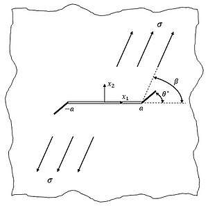
Consider a crack of length housed in an infinite planar body subjected to mixed Mode-I and Mode-II loadings via uniform tension , where is the angle between the original crack plane and the direction of applied tension and is the angle between the original crack plane and the direction of kinking crack growth. Sih, Paris, and Erdogan showed that the stress intensity factors far from the crack tips in this planar loading geometry are simply and .[16] Additionally, Erdogan and Sih[17] postulated the following for this system:


- Crack extension begins at the crack tip
- Crack extension initiates in the plane perpendicular to the direction of greatest tension
- The "maximum stress criterion" is satisfied, i.e., , where is the critical stress intensity factor (and is dependent on fracture toughness )


This postulation implies that the crack begins to extend from its tip in the direction along which the hoop stress is maximum.[17] In other words, the crack begins to extend from its tip in the direction that satisfies the following conditions:

- and .


The hoop stress is written as

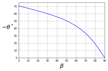
where and are taken with respect to a polar coordinate system oriented at the original crack tip.[17] The direction of crack extension and the envelope of failure (plot of ) are determined by satisfying the postulated criteria. For pure Mode-II loading, is calculated to be .[17]


Maximum hoop stress theory predicts the angle of crack extension in experimental results quite accurately and provides a lower bound to the envelope of failure.[15]
Maximum energy release rate criterion


Consider a crack of length housed in an infinite planar body subjected to a state of constant Mode-I and Mode-II stress applied infinitely far away. Under this loading, the crack will kink with a kink length at an angle with respect to the original crack. Wu[18] postulated that the crack kinks will propagate at a critical angle that maximizes energy release rate defined below. Wu defines and to be the strain energies stored in the specimens containing the straight crack and the kinked crack (or Z-shaped crack), respectively.[18] The energy release rate that is generated when the tips of the straight crack begin to kink is defined as


Thus, the crack will kink and propagate at a critical angle that satisfies the following maximum energy release rate criterion:


is unable to be expressed as a closed-form function, but it can be well approximated though numerical simulation.[18]

For crack in pure Mode-II loading, is calculated to be , which compares well with the maximum hoop stress theory.[18]


Anisotropy
Other factors can also influence the direction of crack growth, such as far-field material deformation (e.g., necking), the presence of micro-separations from defects, the application of compression, the presence of an interface between two heterogeneous materials or material phases, and material anisotropy, to name a few.[14]
In anisotropic materials, the fracture toughness changes as orientation within the material changes. The fracture toughness of an anisotropic material can be defined as , where is some measure of orientation.[15] Therefore, a crack will grow at an orientation angle when the following conditions are satisfied


- and


The above can be considered as a statement of the maximum energy release rate criterion for anisotropic materials.[15]
Crack path stability
The above criteria for predicting crack path (namely the maximum hoop stress theory and the maximum energy release rate criterion) all have the implication that is satisfied at the crack tip as the crack extends with a continuously (or smoothly) turning path. This is often called the criterion of local symmetry.[19]

If a crack path proceeds with a discontinuously sharp change in direction, then may not necessarily coincide with the initial direction of the kinked crack path. But, after such a crack kink has been initiated, then the crack extends so that is satisfied.[19]
Consider a semi-infinite crack in an asymmetric state of loading. A kink propagates from the end of this crack to a point where the coordinate system is aligned with the pre-extended crack tip. Cotterell and Rice applied the criterion of local symmetry to deduce a first-order form of the stress intensity factors for the kinked crack tip and a first order form of the kinked crack path.[19]


| Cotterell and Rice[19]: First-Order Form of the Stress Intensity Factors for the Kinked Crack Tip and First-Order Form of the Kinked Crack Path |
|---|
| First, Cotterell and Rice[19] showed that the stress intensity factors for the extended kinked crack tip are to first order
where and are the tractions on the extended kinked crack from the origin to . Using the stress field on the -axis from the Williams solution,[20] the tractions and can be written to first order as where and are the stress intensity factors for the pre-extended crack tip, , and corresponds to the value of the local stress acting parallel to the pre-extended crack tip, called the stress. For instance, for a straight crack under uniaxial normal stress .[19] Substituting the tractions into the stress intensity factors and then imposing the criterion of local symmetry at the tip of the extending kinking crack leads to the following integral equation of the crack path where can be considered as a normalized stress and can be considered as the initial angle of crack growth, which is necessarily small (so the small angle approximation can be applied). The solution for the crack path is |


The solution for the crack path is


For small values of , the solution for the crack path reduces to the following series expansion


| Crack Path Parameters |
|---|
| where and are the stress intensity factors for the pre-extended crack tip |
| where corresponds to the value of the local stress acting parallel to the pre-extended crack tip, called the stress |
| is the complementary error function |

When , the crack continuously turns further and further away from its initial path with increasing slope as it extends. This is considered as directionally unstable kinked crack growth.[19] When , the crack path continuously extends its initial path. This is considered as neutrally stable kinked crack growth.[19] When , the crack continuously turns away from its initial path with decreasing slope and tends to a steady path of zero slope as it extends. This is considered as directionally stable kinked crack growth.[19]


These theoretical results agree well (for ) with the crack paths observed experimentally by Radon, Leevers, and Culver in experiments on PMMA sheets biaxially loaded with stress normal to the crack and parallel to the crack.[21][22] In this work, the stress is calculated as .[19]


Since the work by Cotterell and Rice was published, it has been found that positive stress cannot be the only indicator for directional instability of kinked crack extension. Support for this claim comes from Melin, who showed that crack growth is directionally unstable for all values of stress in a periodic (regularly-spaced) array of cracks.[23] Furthermore, the kinked crack path and its directional stability cannot be correctly predicted by only considering local effects about the crack edge, as Melin showed through a critical analysis of the Cotterell and Rice solution towards predicting the full kinked crack path arising from a constant remote stress .[24]

Elastic–plastic fracture mechanics
Most engineering materials show some nonlinear elastic and inelastic behavior under operating conditions that involve large loads. In such materials the assumptions of linear elastic fracture mechanics may not hold, that is,
- the plastic zone at a crack tip may have a size of the same order of magnitude as the crack size
- the size and shape of the plastic zone may change as the applied load is increased and also as the crack length increases.
Therefore, a more general theory of crack growth is needed for elastic-plastic materials that can account for:
- the local conditions for initial crack growth which include the nucleation, growth, and coalescence of voids (decohesion) at a crack tip.
- a global energy balance criterion for further crack growth and unstable fracture.
CTOD
Historically, the first parameter for the determination of fracture toughness in the elasto-plastic region was the crack tip opening displacement (CTOD) or "opening at the apex of the crack" indicated. This parameter was determined by Wells during the studies of structural steels, which due to the high toughness could not be characterized with the linear elastic fracture mechanics model. He noted that, before the fracture happened, the walls of the crack were leaving and that the crack tip, after fracture, ranged from acute to rounded off due to plastic deformation. In addition, the rounding of the crack tip was more pronounced in steels with superior toughness.
There are a number of alternative definitions of CTOD. The two most common definitions, CTOD is the displacement at the original crack tip and the 90 degree intercept. The latter definition was suggested by Rice and is commonly used to infer CTOD in finite element models of such. Note that these two definitions are equivalent if the crack tip blunts in a semicircle.
Most laboratory measurements of CTOD have been made on edge-cracked specimens loaded in three-point bending. Early experiments used a flat paddle-shaped gage that was inserted into the crack; as the crack opened, the paddle gage rotated, and an electronic signal was sent to an x-y plotter. This method was inaccurate, however, because it was difficult to reach the crack tip with the paddle gage. Today, the displacement V at the crack mouth is measured, and the CTOD is inferred by assuming the specimen halves are rigid and rotate about a hinge point (the crack tip).
R-curve
An early attempt in the direction of elastic-plastic fracture mechanics was Irwin's crack extension resistance curve, Crack growth resistance curve or R-curve. This curve acknowledges the fact that the resistance to fracture increases with growing crack size in elastic-plastic materials. The R-curve is a plot of the total energy dissipation rate as a function of the crack size and can be used to examine the processes of slow stable crack growth and unstable fracture. However, the R-curve was not widely used in applications until the early 1970s. The main reasons appear to be that the R-curve depends on the geometry of the specimen and the crack driving force may be difficult to calculate.[6]
J-integral
In the mid-1960s James R. Rice (then at Brown University) and G. P. Cherepanov independently developed a new toughness measure to describe the case where there is sufficient crack-tip deformation that the part no longer obeys the linear-elastic approximation. Rice's analysis, which assumes non-linear elastic (or monotonic deformation theory plastic) deformation ahead of the crack tip, is designated the J-integral.[25] This analysis is limited to situations where plastic deformation at the crack tip does not extend to the furthest edge of the loaded part. It also demands that the assumed non-linear elastic behavior of the material is a reasonable approximation in shape and magnitude to the real material's load response. The elastic-plastic failure parameter is designated JIc and is conventionally converted to KIc using Equation (3.1) of the Appendix to this article. Also note that the J integral approach reduces to the Griffith theory for linear-elastic behavior.
The mathematical definition of J-integral is as follows:

where
- is an arbitrary path clockwise around the apex of the crack,
- is the density of strain energy,
- are the components of the vectors of traction,
- are the components of the displacement vectors,
- is an incremental length along the path , and
- and are the stress and strain tensors.


Cohesive zone models
When a significant region around a crack tip has undergone plastic deformation, other approaches can be used to determine the possibility of further crack extension and the direction of crack growth and branching. A simple technique that is easily incorporated into numerical calculations is the cohesive zone model method which is based on concepts proposed independently by Barenblatt[26] and Dugdale[27] in the early 1960s. The relationship between the Dugdale-Barenblatt models and Griffith's theory was first discussed by Willis in 1967.[28] The equivalence of the two approaches in the context of brittle fracture was shown by Rice in 1968.[25] Interest in cohesive zone modeling of fracture has been reignited since 2000 following the pioneering work on dynamic fracture by Xu and Needleman,[29] and Camacho and Ortiz.[30]
Failure Assessment Diagram (FAD)
The Failure Assessment Diagram (FAD) is a common elastic-plastic analysis method.[31] One primary advantage of this method is its simplicity. A failure locus is defined for the material using basic mechanical properties. A factor of safety can be calculated by determining ratios of the applied stress to the yield strength and applied stress intensity to the fracture toughness, and then comparing these ratios to the failure locus.
Transition flaw size
Let a material have a yield strength and a fracture toughness in mode I . Based on fracture mechanics, the material will fail at stress . Based on plasticity, the material will yield when . These curves intersect when . This value of is called as transition flaw size ., and depends on the material properties of the structure. When the , the failure is governed by plastic yielding, and when the failure is governed by fracture mechanics. The value of for engineering alloys is 100 mm and for ceramics is 0.001 mm. If we assume that manufacturing processes can give rise to flaws in the order of micrometers, then, it can be seen that ceramics are more likely to fail by fracture, whereas engineering alloys would fail by plastic deformation.


Crack tip constraint under large scale yielding
Under small-scale yielding conditions, a single parameter (e.g., K, J, or CTOD) characterizes crack tip conditions and can be used as a geometry-independent fracture criterion. Single-parameter fracture mechanics breaks down in the presence of excessive plasticity, and when the fracture toughness depends on the size and geometry of the test specimen. The theories used for large scale yielding is not very standardized. The following theories and approaches are commonly used among researchers in this field.
J-Q Theory
By using FEM, one can establish a parameter Q to modify the stress field for a better solution when the plastic zone is growing. The new stress field is: where for and 0 if not. Q usually takes values from −3 to +2. A negative value greatly changes the geometry of the plastic zone.


The J-Q-M theory includes another parameter, the mismatch parameter, which is used for welds to make up for the change in toughness of the weld metal (WM), base metal (BM) and heat affected zone (HAZ). This value is interpreted to the formula in a similar way as the Q-parameter, and the two are usually assumed to be independent of each other.
T-term effects
As an alternative to J-Q theory, a parameter T can be used. This only changes the normal stress in the x-direction (and the z-direction in the case of plane strain). T does not require the use of FEM but is derived from constraint. It can be argued that T is limited to LEFM, but, as the plastic zone change due to T never reaches the actual crack surface (except on the tip), its validity holds true not only under small-scale yielding. The parameter T also significantly influences on the fracture initiation in brittle materials using maximum tangential strain fracture criterion, as found by the researchers at Texas A&M University.[32] It is found that both parameter T and Poisson's ratio of the material play important roles in the prediction of the crack propagation angle and the mixed mode fracture toughness of the materials.
Engineering applications
The following information is needed for a fracture mechanics prediction of failure:
- Applied load
- Residual stress
- Size and shape of the part
- Size, shape, location, and orientation of the crack
Usually not all of this information is available and conservative assumptions have to be made.
Occasionally post-mortem fracture-mechanics analyses are carried out. In the absence of an extreme overload, the causes are either insufficient toughness (KIc) or an excessively large crack that was not detected during routine inspection.
Appendix: mathematical relations
Griffith's criterion
For the simple case of a thin rectangular plate with a crack perpendicular to the load, the energy release rate, , becomes:
- (1.1)

where is the applied stress, is half the crack length, and is the Young’s modulus, which for the case of plane strain should be divided by the plate stiffness factor . The strain energy release rate can physically be understood as: the rate at which energy is absorbed by growth of the crack.

However, we also have that:
- (1.2)

If ≥ , this is the criterion for which the crack will begin to propagate.

Irwin's modifications
Eventually a modification of Griffith’s solids theory emerged from this work; a term called stress intensity replaced strain energy release rate and a term called fracture toughness replaced surface weakness energy. Both of these terms are simply related to the energy terms that Griffith used:
- (2.1)

and
- (for plane stress) (2.2)

- (for plane strain) (2.3)

where is the stress intensity, the fracture toughness, and is Poisson’s ratio. It is important to recognize the fact that fracture parameter has different values when measured under plane stress and plane strain


Fracture occurs when . For the special case of plane strain deformation, becomes and is considered a material property. The subscript I arises because of the different ways of loading a material to enable a crack to propagate. It refers to so-called "mode I" loading as opposed to mode II or III:

The expression for in equation 2.1 will be different for geometries other than the center-cracked infinite plate, as discussed in the article on the stress intensity factor. Consequently, it is necessary to introduce a dimensionless correction factor, Y, in order to characterize the geometry. This correction factor, also often referred to as the geometric shape factor, is given by empirically determined series and accounts for the type and geometry of the crack or notch. We thus have:
- (2.4)

where Y is a function of the crack length and width of sheet given, for a sheet of finite width W containing a through-thickness crack of length 2a, by:
- (2.5)

For a sheet of finite width W containing a through-thickness edge crack of length a, the geometric shape factor is obtained as: [9]
- (2.6)

Elasticity and plasticity
Since engineers became accustomed to using KIc to characterise fracture toughness, a relation has been used to reduce JIc to it:
- where for plane stress and for plane strain (3.1)


The remainder of the mathematics employed in this approach is interesting, but is probably better summarised in external pages due to its complex nature.
Fracture Mechanism Maps
The fracture-mechanism map is a way of diagram plotted by empirical data of fracture with homologous temperature T/Tm on the horizontal axis, where Tm is the melting temperature, and normalized tensile stress σn/E on the vertical axis, where σn is the nominal stress and E is Young’s modulus. This map represents the dominant fracture mechanism in a material, with contours of time-to-fracture and strain-to-fracture. by comparing mechanisms with the smallest value of time-to-fracture which is the one leading the most quickly to failure. [33]
Micromechanism of fracture
Cleavage
At sufficiently low temperature, cleavage usually dominates the fracture for most crystalline solids because the temperature limits the plasticity of the material and makes it brittle. Generally, cleavage is controlled by nucleation and propagation of cracks either of which can determine the stress at which the specimen fails.[34]
Ductile fracture at low temperature
Ductile fracture requires holes nucleate at inclusion which concentrates stress. Applied stress and plastic strain make holes grow and when, eventually, they are large enough coarsening happens and the material fails.
Transgranular creep fracture
This mechanism happens when the temperature is above 0.3Tm and is the adaptation of low temperature ductile fracture but follows the strain-rate power law in which the creep stabilizes the flow and thereby postpone the coalescence of holes.
Intergranular creep fracture
At low stress, fracture mechanism transfer from transgranular to intergranular which depends on voids and cracks grow at grain boundaries. This regime is determined by diffusion and power-law creep because small voids grow by diffusion at the grain boundary but the space between voids is controlled by deformation creep.
Diffusion fracture
At very low stresses and high temperatures, the diffusion field dominates growing voids and power-law creep is negligible.
Rupture
At very high temperatures, the high rates of recovery relieve the stress at inclusion and suppress the nucleation of internal voids. Therefore, with no other fracture mechanism intervenes, deformation continues until the cross-section area becomes zero.[35]
See also
- AFGROW – Fracture mechanics and fatigue crack growth analysis software
- Concrete fracture analysis – Study of the fracture mechanics of concrete
- Earthquake – Shaking of the surface of the earth caused by a sudden release of energy in the crust
- Fatigue – Weakening of a material caused by varying applied loads
- Fault (geology) – Fracture or discontinuity in rock across which there has been displacement
- Notch (engineering)
- Peridynamics, a numerical method to solve fracture mechanics problems
- Shock (mechanics) – Sudden transient acceleration
- Strength of materials – Behavior of solid objects subject to stresses and strains
- Stress corrosion cracking – The growth of cracks in a corrosive environment
- Structural fracture mechanics – Field of structural engineering concerned with load-carrying structures with one or more failed or damaged components
References
- T.L. Anderson (1995). Fracture Mechanics: Fundamentals and Applications. CRC Press. ISBN 978-0849316562.
- H.L. Ewalds; R.J.H. Wanhill (1984). Fracture Mechanics. Edward Arnold and Delftse Uitgevers Maatschappij. ISBN 978-0-7131-3515-2.
- Griffith, A. A. (1921), "The phenomena of rupture and flow in solids" (PDF), Philosophical Transactions of the Royal Society of London, A, 221 (582–593): 163–198, Bibcode:1921RSPTA.221..163G, doi:10.1098/rsta.1921.0006, archived from the original (PDF) on 2006-10-16.
- Johnson, K. L.; Kendall, K.; Roberts, A. D. (1971-09-08). "Surface energy and the contact of elastic solids". Proc. R. Soc. Lond. A. 324 (1558): 301–313. Bibcode:1971RSPSA.324..301J. doi:10.1098/rspa.1971.0141. ISSN 0080-4630.
- Popov, Valentin L.; Pohrt, Roman; Li, Qiang (2017-09-01). "Strength of adhesive contacts: Influence of contact geometry and material gradients". Friction. 5 (3): 308–325. doi:10.1007/s40544-017-0177-3. ISSN 2223-7690.
- E. Erdogan (2000) Fracture Mechanics, International Journal of Solids and Structures, 37, pp. 171–183.
- Irwin G (1957), Analysis of stresses and strains near the end of a crack traversing a plate, Journal of Applied Mechanics 24, 361–364.
- Orowan, E., 1949. Fracture and strength of solids. Reports on Progress in Physics XII, 185–232.
- Liu, M.; et al. (2015). "An improved semi-analytical solution for stress at round-tip notches" (PDF). Engineering Fracture Mechanics. 149: 134–143. doi:10.1016/j.engfracmech.2015.10.004.
- Alireza Bagher Shemirani; Haeri, H. (2017), "A review paper about experimental investigations on failure behaviour of non-persistent joint", Geomechanics and Engineering, 13 (4): 535–570, doi:10.12989/gae.2017.13.4.535
- Weisshaar, Terry (July 28, 2011). Aerospace Structures- an Introduction to Fundamental Problems. West Lafayette, IN: Purdue University.
- "Crack Tip Plastic Zone Size". Handbook for Damage Tolerant Design. LexTech, Inc. Retrieved 20 November 2016.
- "Retardation". Handbook for Damage Tolerant Design. LexTech, Inc. Retrieved 20 November 2016.
- Broberg, K. B. (1999). Cracks and fracture. San Diego: Academic Press. ISBN 0121341305. OCLC 41233349.
- Zehnder, Alan T. (2012). "Fracture Mechanics". Lecture Notes in Applied and Computational Mechanics. 62. doi:10.1007/978-94-007-2595-9. ISBN 978-94-007-2594-2. ISSN 1613-7736.
- Sih, G. C.; Paris, P. C.; Erdogan, F. (1962). "Crack-Tip, Stress-Intensity Factors for Plane Extension and Plate Bending Problems". Journal of Applied Mechanics. 29 (2): 306. Bibcode:1962JAM....29..306S. doi:10.1115/1.3640546.
- Erdogan, F.; Sih, G. C. (1963). "On the Crack Extension in Plates Under Plane Loading and Transverse Shear". Journal of Basic Engineering. 85 (4): 519. doi:10.1115/1.3656897.
- Wu, Chien H. (1978-07-01). "Maximum-energy-release-rate criterion applied to a tension-compression specimen with crack". Journal of Elasticity. 8 (3): 235–257. doi:10.1007/BF00130464. ISSN 1573-2681.
- Cotterell, B.; Rice, J.R. (1980-04-01). "Slightly curved or kinked cracks". International Journal of Fracture. 16 (2): 155–169. doi:10.1007/BF00012619. ISSN 1573-2673.
- Williams, M. L. (1957). "N/A". Journal of Applied Mechanics. 24: 109–114.
- Radon, J.C.; Leevers, P.S.; Culver, L.E. (1976). "Fracture trajectories in a biaxially stressed plate". J. Mech. Phys. Solids. 24 (6): 381–395. Bibcode:1976JMPSo..24..381L. doi:10.1016/0022-5096(76)90010-7.
- Radon, J.C.; Leevers, P.S.; Culver, L.E. "Fracture Toughness of PMMA Under Biaxial Stress". Fracture. 3: 1113–1118.
- Melin, Solveig (1983-09-01). "Why do cracks avoid each other?". International Journal of Fracture. 23 (1): 37–45. doi:10.1007/BF00020156. ISSN 1573-2673.
- Melin, S. (2002-04-01). "The influence of the T-stress on the directional stability of cracks". International Journal of Fracture. 114 (3): 259–265. doi:10.1023/A:1015521629898. ISSN 1573-2673.
- Rice, J. R. (1968), "A path independent integral and the approximate analysis of strain concentration by notches and cracks" (PDF), Journal of Applied Mechanics, 35 (2): 379–386, Bibcode:1968JAM....35..379R, CiteSeerX 10.1.1.1023.7604, doi:10.1115/1.3601206.
- Barenblatt, G. I. (1962), "The mathematical theory of equilibrium cracks in brittle fracture", Advances in Applied Mechanics, 7: 55–129, doi:10.1016/s0065-2156(08)70121-2, ISBN 9780120020072
- Dugdale, D. S. (1960), "Yielding of steel sheets containing slits", Journal of the Mechanics and Physics of Solids, 8 (2): 100–104, Bibcode:1960JMPSo...8..100D, doi:10.1016/0022-5096(60)90013-2
- Willis, J. R. (1967), "A comparison of the fracture criteria of Griffith and Barenblatt", Journal of the Mechanics and Physics of Solids, 15 (3): 151–162, Bibcode:1967JMPSo..15..151W, doi:10.1016/0022-5096(67)90029-4.
- Xu, X.P.; Needleman, A. (1994), "Numerical simulations of fast crack growth in brittle solids", Journal of the Mechanics and Physics of Solids, 42 (9): 1397–1434, Bibcode:1994JMPSo..42.1397X, doi:10.1016/0022-5096(94)90003-5
- Camacho, G. T.; Ortiz, M. (1996), "Computational modelling of impact damage in brittle materials", International Journal of Solids and Structures, 33 (20–22): 2899–2938, doi:10.1016/0020-7683(95)00255-3
- "Fracture Mechanics".
- Mirsayar, M. M., "Mixed mode fracture analysis using extended maximum tangential strain criterion", Materials & Design, 2015, doi:10.1016/j.matdes.2015.07.135.
- Ashby, M. F.; Gandhi, C.; Taplin, D. M. R. (1 May 1979). "Overview No. 3 Fracture-mechanism maps and their construction for f.c.c. metals and alloys". Acta Metallurgica. 27 (5): 699. doi:10.1016/0001-6160(79)90105-6. ISSN 0001-6160.
- Griffith, Alan Arnold; Taylor, Geoffrey Ingram (1 January 1921). "VI. The phenomena of rupture and flow in solids". Philosophical Transactions of the Royal Society of London. Series A, Containing Papers of a Mathematical or Physical Character. 221 (582–593): 163–198. doi:10.1098/rsta.1921.0006.
- Teirlinck, D.; Zok, F.; Embury, J. D.; Ashby, M. F. (1 May 1988). "Fracture mechanism maps in stress space". Acta Metallurgica. 36 (5): 1213–1228. doi:10.1016/0001-6160(88)90274-X. ISSN 0001-6160.
Bibliography
- Buckley, C.P. "Material Failure", Lecture Notes (2005), University of Oxford.
Further reading
- Davidge, R.W., Mechanical Behavior of Ceramics, Cambridge Solid State Science Series, (1979)
- Demaid, Adrian, Fail Safe, Open University (2004)
- Green, D., An Introduction to the Mechanical Properties of Ceramics, Cambridge Solid State Science Series, Eds. Clarke, D.R., Suresh, S., Ward, I.M. (1998)
- Lawn, B.R., Fracture of Brittle Solids, Cambridge Solid State Science Series, 2nd Edn. (1993)
- Farahmand, B., Bockrath, G., and Glassco, J. (1997) Fatigue and Fracture Mechanics of High-Risk Parts, Chapman & Hall. ISBN 978-0-412-12991-9.
- Chen, X., Mai, Y.-W., Fracture Mechanics of Electromagnetic Materials: Nonlinear Field Theory and Applications, Imperial College Press, (2012)
- A.N. Gent, W.V. Mars, In: James E. Mark, Burak Erman and Mike Roland, Editor(s), Chapter 10 – Strength of Elastomers, The Science and Technology of Rubber, Fourth edition, Academic Press, Boston, 2013, pp. 473–516, ISBN 9780123945846, 10.1016/B978-0-12-394584-6.00010-8
- Zehnder, Alan. Fracture Mechanics, SpringerLink, (2012).
External links
- AFGROW web site AFGROW application web site
- Fracture Mechanics on eFunda site
- Nonlinear Fracture Mechanics Notes by Prof. John Hutchinson, Harvard University
- Notes on Fracture of Thin Films and Multilayers by Prof. John Hutchinson, Harvard University
- Fracture Mechanics by Prof. Piet Schreurs, TU Eindhoven, Netherlands
- Fracturemechanics.org by Dr. Bob McGinty, Mercer University
- Fracture mechanics course notes by Prof. Rui Huang, Univ. of Texas
- Application of Fracture Mechanics on keytometals.com