Aliasing
In signal processing and related disciplines, aliasing is an effect that causes different signals to become indistinguishable (or aliases of one another) when sampled. It also often refers to the distortion or artifact that results when a signal reconstructed from samples is different from the original continuous signal.


Aliasing can occur in signals sampled in time, for instance digital audio, and is referred to as temporal aliasing. It can also occur in spatially sampled signals (e.g. moiré patterns in digital images); this type of aliasing is called spatial aliasing.
Aliasing is generally avoided by applying low pass filters or anti-aliasing filters (AAF) to the input signal before sampling and when converting a signal from a higher to a lower sampling rate. Suitable reconstruction filtering should then be used when restoring the sampled signal to the continuous domain or converting a signal from a lower to a higher sampling rate. For spatial anti-aliasing, the types of anti-aliasing include fast sample anti-aliasing (FSAA), multisample anti-aliasing, and supersampling.
Description

When a digital image is viewed, a reconstruction is performed by a display or printer device, and by the eyes and the brain. If the image data is processed in some way during sampling or reconstruction, the reconstructed image will differ from the original image, and an alias is seen.
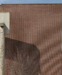
An example of spatial aliasing is the moiré pattern observed in a poorly pixelized image of a brick wall. Spatial anti-aliasing techniques avoid such poor pixelizations. Aliasing can be caused either by the sampling stage or the reconstruction stage; these may be distinguished by calling sampling aliasing prealiasing and reconstruction aliasing postaliasing.[1]
Temporal aliasing is a major concern in the sampling of video and audio signals. Music, for instance, may contain high-frequency components that are inaudible to humans. If a piece of music is sampled at 32000 samples per second (Hz), any frequency components at or above 16000 Hz (the Nyquist frequency for this sampling rate) will cause aliasing when the music is reproduced by a digital-to-analog converter (DAC). To prevent this, an anti-aliasing filter is used to remove components above the Nyquist frequency prior to sampling.
In video or cinematography, temporal aliasing results from the limited frame rate, and causes the wagon-wheel effect, whereby a spoked wheel appears to rotate too slowly or even backwards. Aliasing has changed its apparent frequency of rotation. A reversal of direction can be described as a negative frequency. Temporal aliasing frequencies in video and cinematography are determined by the frame rate of the camera, but the relative intensity of the aliased frequencies is determined by the shutter timing (exposure time) or the use of a temporal aliasing reduction filter during filming.[2]
Like the video camera, most sampling schemes are periodic; that is, they have a characteristic sampling frequency in time or in space. Digital cameras provide a certain number of samples (pixels) per degree or per radian, or samples per mm in the focal plane of the camera. Audio signals are sampled (digitized) with an analog-to-digital converter, which produces a constant number of samples per second. Some of the most dramatic and subtle examples of aliasing occur when the signal being sampled also has periodic content.
Bandlimited functions
Actual signals have a finite duration and their frequency content, as defined by the Fourier transform, has no upper bound. Some amount of aliasing always occurs when such functions are sampled. Functions whose frequency content is bounded (bandlimited) have an infinite duration in the time domain. If sampled at a high enough rate, determined by the bandwidth, the original function can, in theory, be perfectly reconstructed from the infinite set of samples.
Bandpass signals
Sometimes aliasing is used intentionally on signals with no low-frequency content, called bandpass signals. Undersampling, which creates low-frequency aliases, can produce the same result, with less effort, as frequency-shifting the signal to lower frequencies before sampling at the lower rate. Some digital channelizers[3] exploit aliasing in this way for computational efficiency. See Sampling (signal processing), Nyquist rate (relative to sampling), and Filter bank.
Sampling sinusoidal functions
Sinusoids are an important type of periodic function, because realistic signals are often modeled as the summation of many sinusoids of different frequencies and different amplitudes (for example, with a Fourier series or transform). Understanding what aliasing does to the individual sinusoids is useful in understanding what happens to their sum.
When sampling a function at frequency fs (intervals 1/fs), the following functions yield identical sets of samples: {sin(2π( f+Nfs) t + φ), N = 0, ±1, ±2, ±3,...}. A frequency spectrum of the samples produces equally strong responses at all those frequencies. Without collateral information, the frequency of the original function is ambiguous. So the functions and their frequencies are said to be aliases of each other. Noting the trigonometric identity:
we can write all the alias frequencies as positive values: fN( f ) | f+N fs| .

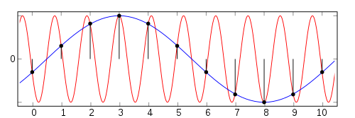
For example, here a plot depicts a set of samples with parameter fs = 1, and two different sinusoids that could have produced the samples. Nine cycles of the red sinusoid and one cycle of the blue sinusoid span an interval of 10 samples. The corresponding number of cycles per sample are fred = 0.9fs and fblue = 0.1fs. So the N = −1 alias of fred is fblue (and vice versa).
Aliasing matters when one attempts to reconstruct the original waveform from its samples. The most common reconstruction technique produces the smallest of the fN( f ) frequencies. So it is usually important that f0( f ) be the unique minimum. A necessary and sufficient condition for that is fs/2 > | f |, where fs/2 is commonly called the Nyquist frequency of a system that samples at rate fs. In our example, the Nyquist condition is satisfied if the original signal is the blue sinusoid ( f = fblue). But if f = fred = 0.9fs, the usual reconstruction method will produce the blue sinusoid instead of the red one.
Folding
In the example above, fred and fblue are symmetrical around the frequency fs/2. And in general, as f increases from 0 to fs/2, f−1( f ) decreases from fs to fs/2. Similarly, as f increases from fs/2 to fs, f−1( f ) continues decreasing from fs/2 to 0.
A graph of amplitude vs frequency for a single sinusoid at frequency 0.6 fs and some of its aliases at 0.4 fs, 1.4 fs, and 1.6 fs would look like the 4 black dots in the first figure below. The red lines depict the paths (loci) of the 4 dots if we were to adjust the frequency and amplitude of the sinusoid along the solid red segment (between fs/2 and fs). No matter what function we choose to change the amplitude vs frequency, the graph will exhibit symmetry between 0 and fs. This symmetry is commonly referred to as folding, and another name for fs/2 (the Nyquist frequency) is folding frequency. Folding is often observed in practice when viewing the frequency spectrum of real-valued samples, such as the second figure below.
 The black dots are aliases of each other. The solid red line is an example of amplitude varying with frequency. The dashed red lines are the corresponding paths of the aliases. |
 The Fourier transform of music sampled at 44100 samples/sec exhibits symmetry (called "folding") around the Nyquist frequency (22050 Hz). |
 Graph of frequency aliasing, showing folding frequency and periodicity. Frequencies above fs/2 have an alias below fs/2, whose value is given by this graph. |

Complex sinusoids
Complex sinusoids are waveforms whose samples are complex numbers, and the concept of negative frequency is necessary to distinguish them. In that case, the frequencies of the aliases are given by just: fN( f ) = f + N fs. Therefore, as f increases from fs/2 to fs, f−1( f ) goes from –fs/2 up to 0. Consequently, complex sinusoids do not exhibit folding. Complex samples of real-valued sinusoids have zero-valued imaginary parts and do exhibit folding.
Sample frequency

When the condition fs/2 > f is met for the highest frequency component of the original signal, then it is met for all the frequency components, a condition called the Nyquist criterion. That is typically approximated by filtering the original signal to attenuate high frequency components before it is sampled. These attenuated high frequency components still generate low-frequency aliases, but typically at low enough amplitudes that they do not cause problems. A filter chosen in anticipation of a certain sample frequency is called an anti-aliasing filter.
The filtered signal can subsequently be reconstructed, by interpolation algorithms, without significant additional distortion. Most sampled signals are not simply stored and reconstructed. But the fidelity of a theoretical reconstruction (via the Whittaker–Shannon interpolation formula) is a customary measure of the effectiveness of sampling.
Historical usage
Historically the term aliasing evolved from radio engineering because of the action of superheterodyne receivers. When the receiver shifts multiple signals down to lower frequencies, from RF to IF by heterodyning, an unwanted signal, from an RF frequency equally far from the local oscillator (LO) frequency as the desired signal, but on the wrong side of the LO, can end up at the same IF frequency as the wanted one. If it is strong enough it can interfere with reception of the desired signal. This unwanted signal is known as an image or alias of the desired signal.
Angular aliasing
Aliasing occurs whenever the use of discrete elements to capture or produce a continuous signal causes frequency ambiguity.
Spatial aliasing, particular of angular frequency, can occur when reproducing a light field[4] or sound field with discrete elements, as in 3D displays or wave field synthesis of sound.
This aliasing is visible in images such as posters with lenticular printing: if they have low angular resolution, then as one moves past them, say from left-to-right, the 2D image does not initially change (so it appears to move left), then as one moves to the next angular image, the image suddenly changes (so it jumps right) – and the frequency and amplitude of this side-to-side movement corresponds to the angular resolution of the image (and, for frequency, the speed of the viewer's lateral movement), which is the angular aliasing of the 4D light field.
The lack of parallax on viewer movement in 2D images and in 3-D film produced by stereoscopic glasses (in 3D films the effect is called "yawing", as the image appears to rotate on its axis) can similarly be seen as loss of angular resolution, all angular frequencies being aliased to 0 (constant).
More examples
Online audio example
The qualitative effects of aliasing can be heard in the following audio demonstration. Six sawtooth waves are played in succession, with the first two sawtooths having a fundamental frequency of 440 Hz (A4), the second two having fundamental frequency of 880 Hz (A5), and the final two at 1760 Hz (A6). The sawtooths alternate between bandlimited (non-aliased) sawtooths and aliased sawtooths and the sampling rate is 22.05 kHz. The bandlimited sawtooths are synthesized from the sawtooth waveform's Fourier series such that no harmonics above the Nyquist frequency are present.
The aliasing distortion in the lower frequencies is increasingly obvious with higher fundamental frequencies, and while the bandlimited sawtooth is still clear at 1760 Hz, the aliased sawtooth is degraded and harsh with a buzzing audible at frequencies lower than the fundamental.
Direction finding
A form of spatial aliasing can also occur in antenna arrays or microphone arrays used to estimate the direction of arrival of a wave signal, as in geophysical exploration by seismic waves. Waves must be sampled more densely than two points per wavelength, or the wave arrival direction becomes ambiguous.[5]
See also
| Wikimedia Commons has media related to Aliasing. |
Notes
Citations
- Mitchell, Don P.; Netravali, Arun N. (August 1988). Reconstruction filters in computer-graphics (PDF). ACM SIGGRAPH International Conference on Computer Graphics and Interactive Techniques. 22. pp. 221–228. doi:10.1145/54852.378514. ISBN 0-89791-275-6.
- Tessive, LLC (2010)."Time Filter Technical Explanation"
- harris, frederic j. (Aug 2006). Multirate Signal Processing for Communication Systems. Upper Saddle River, NJ: Prentice Hall PTR. ISBN 978-0-13-146511-4.
- The (New) Stanford Light Field Archive
- Flanagan, James L., "Beamwidth and useable bandwidth of delay-steered microphone arrays", AT&T Tech. J., 1985, 64, pp. 983–995
Further reading
- Pharr, Matt; Humphreys, Greg. (28 June 2010). Physically Based Rendering: From Theory to Implementation. Morgan Kaufmann. ISBN 978-0-12-375079-2. Chapter 7 (Sampling and reconstruction). Retrieved 3 March 2013.
- Aliasing by a sampling oscilloscope on YouTube by Tektronix Application Engineer
- Anti-Aliasing Filter Primer by La Vida Leica, discusses its purpose and effect on recorded images
- Interactive examples demonstrating the aliasing effect