Superheterodyne receiver
A superheterodyne receiver, often shortened to superhet, is a type of radio receiver that uses frequency mixing to convert a received signal to a fixed intermediate frequency (IF) which can be more conveniently processed than the original carrier frequency. It was invented by US engineer Edwin Armstrong in 1918 during World War I.[1] Virtually all modern radio receivers use the superheterodyne principle.
History
Heterodyne
Early Morse code radio broadcasts were produced using an alternator connected to a spark gap. The output signal was at a carrier frequency defined by the physical construction of the gap, modulated by the alternating current signal from the alternator. Since the output of the alternator was generally in the audible range, this produces an audible amplitude modulated (AM) signal. Simple radio detectors filtered out the high-frequency carrier, leaving the modulation, which was passed on to the user's headphones as an audible signal of dots and dashes.
In 1904, Ernst Alexanderson introduced the Alexanderson alternator, a device that directly produced radio frequency output with higher power and much higher efficiency than the older spark gap systems. In contrast to the spark gap, however, the output from the alternator was a pure carrier wave at a selected frequency. When detected on existing receivers, the dots and dashes would normally be inaudible, or "supersonic". Due to the filtering effects of the receiver, these signals generally produced a click or thump, which were audible but made determining dot or dash difficult.
In 1905, Canadian inventor Reginald Fessenden came up with the idea of using two Alexanderson alternators operating at closely spaced frequencies to broadcast the signals, instead of one. The receiver would then receive both signals, and as part of the detection process, only the beat frequency would exit the receiver. By selecting two carriers close enough that the beat frequency was audible, the resulting Morse code could once again be easily heard even in simple receivers. For instance, if the two alternators operated at frequencies 3 kHz apart, the output in the headphones would be dots or dashes of 3 kHz tone, making them easily audible.
Fessenden coined the term "heterodyne," meaning "generated by a difference" (in frequency), to describe this system. The word is derived from the Greek roots hetero- "different", and -dyne "power".
Regeneration
Morse code was widely used in the early days of radio because it was easy both to produce the signal as well as receive it. Because the output from the amplifier does not have to closely match the original modulation of the received signal, in contrast to voice broadcasts, any number of simple amplification systems could be used. One was due to an interesting side-effect of the construction of early triode amplifier tubes. If both the plate (anode) and grid are connected to resonant circuits tuned to the same frequency, stray capacitive coupling between the grid and the plate will cause the amplifier to go into oscillation if the stage gain is much more than unity.
In 1913, Edwin Howard Armstrong described a receiver system that used this effect to produce audible Morse code output using a single triode. The output of the anode, the output signal after amplification, was connected back to the input through a "tickler", causing feedback that drove input signals well beyond unity. This caused the output to oscillate at a chosen frequency with great amplification. When the original signal cut off at the end of the dot or dash, the oscillation decayed again and the sound disappeared after a short delay.
Armstrong referred to this concept as a regenerative receiver, and it immediately became one of the most widely used systems of its era. Many radio systems of the 1920s were based on the regenerative principle, and it continued to be used in specialized roles into the 1940s, for instance in the IFF Mark II.
RDF
There was one role where the regenerative system was not suitable, even for Morse code sources, and that was the task of radio direction finding, or RDF.
The regenerative system was highly non-linear, amplifying any signal above a certain threshold by a huge amount, sometimes so large it caused it to turn into a transmitter (which was the entire concept behind IFF). In RDF, the strength of the signal is used to determine the location of the transmitter, so one requires linear amplification to allow the strength of the original signal, often very weak, to be accurately measured.
To address this need, RDF systems of the era used triodes operating below unity. To get a usable signal from such a system, tens or even hundreds of triodes had to be used, connected together anode-to-grid. These amplifiers drew enormous amounts of power and required a team of maintenance engineers to keep them running. Nevertheless, the strategic value of direction finding on weak signals was so high that the British Admiralty felt the high cost was justified.
Superheterodyne
Although a number of researchers discovered the superheterodyne concept, filing patents only months apart (see below), Armstrong is often credited with the concept. He came across it while considering better ways to produce RDF receivers. He had concluded that moving to higher "short wave" frequencies would make RDF more useful and was looking for practical means to build a linear amplifier for these signals. At the time, short wave was anything above about 500 kHz, beyond any existing amplifier's capabilities.
It had been noticed that when a regenerative receiver went into oscillation, other nearby receivers would start picking up other stations as well. Armstrong (and others) eventually deduced that this was caused by a "supersonic heterodyne" between the station's carrier frequency and the regenerative receiver's oscillation frequency. When the first receiver began to oscillate at high outputs, its signal would flow back out through the antenna to be received on any nearby receiver. On that receiver, the two signals mixed just as they did in the original heterodyne concept, producing an output that is the difference in frequency between the two signals.
For instance, consider a lone receiver that was tuned to a station at 300 kHz. If a second receiver is set up nearby and set to 400 kHz with high gain, it will begin to give off a 400 kHz signal that will be received in the first receiver. In that receiver, the two signals will mix to produce four outputs, one at the original 300 kHz, another at the received 400 kHz, and two more, the difference at 100 kHz and the sum at 700 kHz. This is the same effect that Fessenden had proposed, but in his system the two frequencies were deliberately chosen so the beat frequency was audible. In this case, all of the frequencies are well beyond the audible range, and thus "supersonic", giving rise to the name superheterodyne.
Armstrong realized that this effect was a potential solution to the "short wave" amplification problem, as the "difference" output still retained its original modulation, but on a lower carrier frequency. In the example above, one can amplify the 100 kHz beat signal and retrieve the original information from that, the receiver does not have to tune in the higher 300 kHz original carrier. By selecting an appropriate set of frequencies, even very high-frequency signals could be "reduced" to a frequency that could be amplified by existing systems.
For instance, to receive a signal at 1500 kHz, far beyond the range of efficient amplification at the time, one could set up an oscillator at, for example, 1560 kHz. Armstrong referred to this as the "local oscillator" or LO. As its signal was being fed into a second receiver in the same device, it did not have to be powerful, generating only enough signal to be roughly similar in strength to that of the received station.[lower-alpha 1] When the signal from the LO mixes with the station's, one of the outputs will be the heterodyne difference frequency, in this case, 60 kHz. He termed this resulting difference the "intermediate frequency" often abbreviated to "IF".
In December 1919, Major E. H. Armstrong gave publicity to an indirect method of obtaining short-wave amplification, called the super-heterodyne. The idea is to reduce the incoming frequency, which may be, for example 1,500,000 cycles (200 meters), to some suitable super-audible frequency that can be amplified efficiently, then passing this current through an intermediate frequency amplifier, and finally rectifying and carrying on to one or two stages of audio frequency amplification.[2]
The "trick" to the superheterodyne is that by changing the LO frequency you can tune in different stations. For instance, to receive a signal at 1300 kHz, one could tune the LO to 1360 kHz, resulting in the same 60 kHz IF. This means the amplifier section can be tuned to operate at a single frequency, the design IF, which is much easier to do efficiently.
Development
Armstrong put his ideas into practice, and the technique was soon adopted by the military. It was less popular when commercial radio broadcasting began in the 1920s, mostly due to the need for an extra tube (for the oscillator), the generally higher cost of the receiver, and the level of skill required to operate it. For early domestic radios, tuned radio frequency receivers (TRF) were more popular because they were cheaper, easier for a non-technical owner to use, and less costly to operate. Armstrong eventually sold his superheterodyne patent to Westinghouse, who then sold it to Radio Corporation of America (RCA), the latter monopolizing the market for superheterodyne receivers until 1930.[4]
Early superheterodyne receivers used IFs as low as 20 kHz, often based on the self-resonance of iron-core transformers. This made them extremely susceptible to image frequency interference, but at the time, the main objective was sensitivity rather than selectivity. Using this technique, a small number of triodes could do the work that formerly required dozens of triodes.
In the 1920s, commercial IF filters looked very similar to 1920s audio interstage coupling transformers, had similar construction and were wired up in an almost identical manner, and so they were referred to as "IF transformers". By the mid-1930s superheterodynes were using much higher intermediate frequencies, (typically around 440–470 kHz), with tuned coils similar in construction to the aerial and oscillator coils. The name "IF transformer" was retained and is still used today. Modern receivers typically use a mixture of ceramic resonator or SAW (surface-acoustic wave) resonators as well as traditional tuned-inductor IF transformers.
By the 1930s, improvements in vacuum tube technology rapidly eroded the TRF receiver's cost advantages, and the explosion in the number of broadcasting stations created a demand for cheaper, higher-performance receivers.
The development of the tetrode vacuum tube containing a screen grid led to a multi-element tube in which the mixer and oscillator functions could be combined, first used in the so-called autodyne mixer. This was rapidly followed by the introduction of tubes specifically designed for superheterodyne operation, most notably the pentagrid converter. By reducing the tube count, this further reduced the advantage of preceding receiver designs.
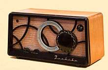
By the mid-1930s, commercial production of TRF receivers was largely replaced by superheterodyne receivers. By the 1940s the vacuum-tube superheterodyne AM broadcast receiver was refined into a cheap-to-manufacture design called the "All American Five", because it uses five vacuum tubes: usually a converter (mixer/local oscillator), an IF amplifier, a detector/audio amp, audio power amp, and a rectifier. From this time, the superheterodyne design was used for virtually all commercial radio and TV receivers.
Patent battles
French engineer Lucien Lévy filed a patent application for the superheterodyne principle in August 1917 with brevet n° 493660.[5] Armstrong also filed his patent in 1917.[6][7][8] Levy filed his original disclosure about seven months before Armstrong's.[9] German inventor Walter H. Schottky also filed a patent in 1918.[5]
At first the US recognised Armstrong as the inventor, and his US Patent 1,342,885 was issued on 8 June 1920.[9] After various changes and court hearings Lévy was awarded US patent No 1,734,938 that included seven of the nine claims in Armstrong's application, while the two remaining claims were granted to Alexanderson of GE and Kendall of AT&T.[9]
Principle of operation
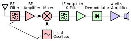
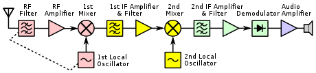
The diagram at right shows the block diagram of a typical single-conversion superheterodyne receiver. The diagram has blocks that are common to superheterodyne receivers,[10] with only the RF amplifier being optional.
The antenna collects the radio signal. The tuned RF stage with optional RF amplifier provides some initial selectivity; it is necessary to suppress the image frequency (see below), and may also serve to prevent strong out-of-passband signals from saturating the initial amplifier. A local oscillator provides the mixing frequency; it is usually a variable frequency oscillator which is used to tune the receiver to different stations. The frequency mixer does the actual heterodyning that gives the superheterodyne its name; it changes the incoming radio frequency signal to a higher or lower, fixed, intermediate frequency (IF). The IF band-pass filter and amplifier supply most of the gain and the narrowband filtering for the radio. The demodulator extracts the audio or other modulation from the IF radio frequency. The extracted signal is then amplified by the audio amplifier.
Circuit description
To receive a radio signal, a suitable antenna is required. The output of the antenna may be very small, often only a few microvolts. The signal from the antenna is tuned and may be amplified in a so-called radio frequency (RF) amplifier, although this stage is often omitted. One or more tuned circuits at this stage block frequencies that are far removed from the intended reception frequency. To tune the receiver to a particular station, the frequency of the local oscillator is controlled by the tuning knob (for instance). Tuning of the local oscillator and the RF stage may use a variable capacitor, or varicap diode.[11] The tuning of one (or more) tuned circuits in the RF stage must track the tuning of the local oscillator.
Local oscillator and mixer
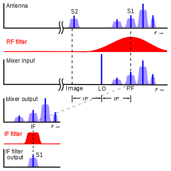
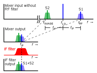
The signal is then fed into a circuit where it is mixed with a sine wave from a variable frequency oscillator known as the local oscillator (LO). The mixer uses a non-linear component to produce both sum and difference beat frequencies signals,[12] each one containing the modulation contained in the desired signal. The output of the mixer may include the original RF signal at fRF, the local oscillator signal at fLO, and the two new heterodyne frequencies fRF + fLO and fRF − fLO. The mixer may inadvertently produce additional frequencies such as third- and higher-order intermodulation products. Ideally, the IF bandpass filter removes all but the desired IF signal at fIF. The IF signal contains the original modulation (transmitted information) that the received radio signal had at fRF.
The frequency of the local oscillator fLO is set so the desired reception radio frequency fRF mixes to fIF. There are two choices for the local oscillator frequency because the dominant mixer products are at fRF ± fLO. If the local oscillator frequency is less than the desired reception frequency, it is called low-side injection (fIF = fRF − fLO); if the local oscillator is higher, then it is called high-side injection (fIF = fLO − fRF).
The mixer will process not only the desired input signal at fRF, but also all signals present at its inputs. There will be many mixer products (heterodynes). Most other signals produced by the mixer (such as due to stations at nearby frequencies) can be filtered out in the IF tuned amplifier; that gives the superheterodyne receiver its superior performance. However, if fLO is set to fRF + fIF, then an incoming radio signal at fLO + fIF will also produce a heterodyne at fIF; the frequency fLO + fIF is called the image frequency and must be rejected by the tuned circuits in the RF stage. The image frequency is 2 fIF higher (or lower) than the desired frequency fRF, so employing a higher IF frequency fIF increases the receiver's image rejection without requiring additional selectivity in the RF stage.
To suppress the unwanted image, the tuning of the RF stage and the LO may need to "track" each other. In some cases, a narrow-band receiver can have a fixed tuned RF amplifier. In that case, only the local oscillator frequency is changed. In most cases, a receiver's input band is wider than its IF center frequency. For example, a typical AM broadcast band receiver covers 510 kHz to 1655 kHz (a roughly 1160 kHz input band) with a 455 kHz IF frequency; an FM broadcast band receiver covers 88 MHz to 108 MHz band with a 10.7 MHz IF frequency. In that situation, the RF amplifier must be tuned so the IF amplifier does not see two stations at the same time. If the AM broadcast band receiver LO were set at 1200 kHz, it would see stations at both 745 kHz (1200−455 kHz) and 1655 kHz. Consequently, the RF stage must be designed so that any stations that are twice the IF frequency away are significantly attenuated. The tracking can be done with a multi-section variable capacitor or some varactors driven by a common control voltage. An RF amplifier may have tuned circuits at both its input and its output, so three or more tuned circuits may be tracked. In practice, the RF and LO frequencies need to track closely but not perfectly.[13][14]
In many superheterodyne receivers the same stage is used as both the local oscillator and the mixer, to save cost, power and size. This is called a converter. In vacuum tube receivers, a single pentagrid converter tube would oscillate and also provide signal amplification as well as frequency shifting.[15]
IF amplifier
The stages of an intermediate frequency amplifier ("IF amplifier" or "IF strip") are tuned to a fixed frequency that does not change as the receiving frequency changes. The fixed frequency simplifies optimization of the IF amplifier.[10] The IF amplifier is selective around its center frequency fIF. The fixed center frequency allows the stages of the IF amplifier to be carefully tuned for best performance (this tuning is called "aligning" the IF amplifier). If the center frequency changed with the receiving frequency, then the IF stages would have had to track their tuning. That is not the case with the superheterodyne.
Typically, the IF center frequency fIF is chosen to be less than the desired reception frequency fRF. The choice has some performance advantages. First, it is easier and less expensive to get high selectivity at a lower frequency. For the same bandwidth, a tuned circuit at a lower frequency needs a lower Q. Stated another way, for the same filter technology, a higher center frequency will take more IF filter stages to achieve the same selectivity bandwidth. Second, it is easier and less expensive to get high gain at a lower frequency. When used at high frequencies, many amplifiers show a constant gain–bandwidth product (dominant pole) characteristic. If an amplifier has a gain–bandwidth product of 100 MHz, then it would have a voltage gain of 100 at 1 MHz but only 10 at 10 MHz. If the IF amplifier needed a voltage gain of 10,000, then it would need only two stages with an IF at 1 MHz but four stages at 10 MHz.
Usually the intermediate frequency is lower than the reception frequency fRF, but in some modern receivers (e.g. scanners and spectrum analyzers) a higher IF frequency is used to minimize problems with image rejection or gain the benefits of fixed-tuned stages. The Rohde & Schwarz EK-070 VLF/HF receiver covers 10 kHz to 30 MHz.[16] It has a band switched RF filter and mixes the input to a first IF of 81.4 MHz. The first LO frequency is 81.4 to 111.4 MHz, so the primary images are far away. The first IF stage uses a crystal filter with a 12 kHz bandwidth. There is a second frequency conversion (making a triple-conversion receiver) that mixes the 81.4 MHz first IF with 80 MHz to create a 1.4 MHz second IF. Image rejection for the second IF is not a major problem because the first IF provides adequate image rejection and the second mixer is fixed tuned.
To avoid interference to receivers, licensing authorities will avoid assigning common IF frequencies to transmitting stations. Standard intermediate frequencies used are 455 kHz for medium-wave AM radio, 10.7 MHz for broadcast FM receivers, 38.9 MHz (Europe) or 45 MHz (US) for television, and 70 MHz for satellite and terrestrial microwave equipment. To avoid tooling costs associated with these components, most manufacturers then tended to design their receivers around a fixed range of frequencies offered, which resulted in a worldwide de facto standardization of intermediate frequencies.
In early superhets, the IF stage was often a regenerative stage providing the sensitivity and selectivity with fewer components. Such superhets were called super-gainers or regenerodynes.[17] Another circuit added to the intermediate frequency chain is the Q multiplier.
IF bandpass filter
The IF stage includes a filter and/or multiple tuned circuits to achieve the desired selectivity. This filtering must have a band pass equal to or less than the frequency spacing between adjacent broadcast channels. Ideally a filter would have a high attenuation to adjacent channels, but maintain a flat response across the desired signal spectrum in order to retain the quality of the received signal. This may be obtained using one or more dual tuned IF transformers, a quartz crystal filter, or a multipole ceramic crystal filter.[18]
In the case of television receivers, no other technique was able to produce the precise bandpass characteristic needed for vestigial sideband reception, such as that used in the NTSC system first approved by the US in 1941. By the 1980s, multi-component capacitor-inductor filters had been replaced with precision electromechanical surface acoustic wave (SAW) filters. Fabricated by precision laser milling techniques, SAW filters are cheaper to produce, can be made to extremely close tolerances, and are very stable in operation.
Demodulator
The received signal is now processed by the demodulator stage where the audio signal (or other baseband signal) is recovered and then further amplified. AM demodulation requires the simple rectification of the RF signal (so-called envelope detection), and a simple RC low pass filter to remove remnants of the intermediate frequency.[19] FM signals may be detected using a discriminator, ratio detector, or phase-locked loop. Continuous wave and single sideband signals require a product detector using a so-called beat frequency oscillator, and there are other techniques used for different types of modulation.[20] The resulting audio signal (for instance) is then amplified and drives a loudspeaker.
When so-called high-side injection has been used, where the local oscillator is at a higher frequency than the received signal (as is common), then the frequency spectrum of the original signal will be reversed. This must be taken into account by the demodulator (and in the IF filtering) in the case of certain types of modulation such as single sideband.
Multiple conversion
To overcome obstacles such as image response, some receivers use multiple successive stages of frequency conversion and multiple IFs of different values. A receiver with two frequency conversions and IFs is called a dual conversion superheterodyne, and one with three IFs is called a triple conversion superheterodyne.
The main reason that this is done is that with a single IF there is a tradeoff between low image response and selectivity. The separation between the received frequency and the image frequency is equal to twice the IF frequency, so the higher the IF, the easier it is to design an RF filter to remove the image frequency from the input and achieve low image response. However, the higher the IF, the more difficult it is to achieve high selectivity in the IF filter. At shortwave frequencies and above, the difficulty in obtaining sufficient selectivity in the tuning with the high IFs needed for low image response impacts performance. To solve this problem two IF frequencies can be used, first converting the input frequency to a high IF to achieve low image response, and then converting this frequency to a low IF to achieve good selectivity in the second IF filter. To improve tuning, a third IF can be used.
For example, for a receiver that can tune from 500 kHz to 30 MHz, three frequency converters might be used.[10] With a 455 kHz IF it is easy to get adequate front end selectivity with broadcast band (under 1600 kHz) signals. For example, if the station being received is on 600 kHz, the local oscillator can be set to 1055 kHz, giving an image on (-600+1055=) 455 kHz. But a station on 1510 kHz could also potentially produce an image at (1510-1055=) 455 kHz and so cause image interference. However, because 600 kHz and 1510 kHz are so far apart, it is easy to design the front end tuning to reject the 1510 kHz frequency.
However at 30 MHz, things are different. The oscillator would be set to 30.455 MHz to produce a 455 kHz IF, but a station on 30.910 would also produce a 455 kHz beat, so both stations would be heard at the same time. But it is virtually impossible to design an RF tuned circuit that can adequately discriminate between 30 MHz and 30.91 MHz, so one approach is to "bulk downconvert" whole sections of the shortwave bands to a lower frequency, where adequate front-end tuning is easier to arrange.
For example, the ranges 29 MHz to 30 MHz; 28 MHz to 29 MHz etc. might be converted down to 2 MHz to 3 MHz, there they can be tuned more conveniently. This is often done by first converting each "block" up to a higher frequency (typically 40 MHz) and then using a second mixer to convert it down to the 2 MHz to 3 MHz range. The 2 MHz to 3 MHz "IF" is basically another self-contained superheterodyne receiver, most likely with a standard IF of 455 kHz.
Modern designs
Microprocessor technology allows replacing the superheterodyne receiver design by a software defined radio architecture, where the IF processing after the initial IF filter is implemented in software. This technique is already in use in certain designs, such as very low-cost FM radios incorporated into mobile phones, since the system already has the necessary microprocessor.
Radio transmitters may also use a mixer stage to produce an output frequency, working more or less as the reverse of a superheterodyne receiver.
Advantages and disadvantages
Superheterodyne receivers have essentially replaced all previous receiver designs. The development of modern semiconductor electronics negated the advantages of designs (such as the regenerative receiver) that used fewer vacuum tubes. The superheterodyne receiver offers superior sensitivity, frequency stability and selectivity. Compared with the tuned radio frequency receiver (TRF) design, superhets offer better stability because a tuneable oscillator is more easily realized than a tuneable amplifier. Operating at a lower frequency, IF filters can give narrower passbands at the same Q factor than an equivalent RF filter. A fixed IF also allows the use of a crystal filter[10] or similar technologies that cannot be tuned. Regenerative and super-regenerative receivers offered a high sensitivity, but often suffer from stability problems making them difficult to operate.
Although the advantages of the superhet design are overwhelming, there are a few drawbacks that need to be tackled in practice.
Image frequency (fIMAGE)


One major disadvantage to the superheterodyne receiver is the problem of image frequency. In heterodyne receivers, an image frequency is an undesired input frequency equal to the station frequency plus (or minus) twice the intermediate frequency. The image frequency results in two stations being received at the same time, thus producing interference. Image frequencies can be eliminated by sufficient attenuation on the incoming signal by the RF amplifier filter of the superheterodyne receiver.

For example, an AM broadcast station at 580 kHz is tuned on a receiver with a 455 kHz IF. The local oscillator is tuned to 580 + 455 = 1035 kHz. But a signal at 580 + 455 + 455 = 1490 kHz is also 455 kHz away from the local oscillator; so both the desired signal and the image, when mixed with the local oscillator, will appear at the intermediate frequency. This image frequency is within the AM broadcast band. Practical receivers have a tuning stage before the converter, to greatly reduce the amplitude of image frequency signals; additionally, broadcasting stations in the same area have their frequencies assigned to avoid such images.
The unwanted frequency is called the image of the wanted frequency, because it is the "mirror image" of the desired frequency reflected . A receiver with inadequate filtering at its input will pick up signals at two different frequencies simultaneously: the desired frequency and the image frequency. Any noise or random radio station at the image frequency can interfere with reception of the desired signal.

Early Autodyne receivers typically used IFs of only 150 kHz or so, as it was difficult to maintain reliable oscillation if higher frequencies were used. As a consequence, most Autodyne receivers needed quite elaborate antenna tuning networks, often involving double-tuned coils, to avoid image interference. Later superhets used tubes specially designed for oscillator/mixer use, which were able to work reliably with much higher IFs, reducing the problem of image interference and so allowing simpler and cheaper aerial tuning circuitry.
Sensitivity to the image frequency can be minimized only by (1) a filter that precedes the mixer or (2) a more complex mixer circuit [21] that suppresses the image. In most receivers, this is accomplished by a bandpass filter in the RF front end. In many tunable receivers, the bandpass filter is tuned in tandem with the local oscillator.
Image rejection is an important factor in choosing the intermediate frequency of a receiver. The farther apart the bandpass frequency and the image frequency are, the more the bandpass filter will attenuate any interfering image signal. Since the frequency separation between the bandpass and the image frequency is , a higher intermediate frequency improves image rejection. It may be possible to use a high enough first IF that a fixed-tuned RF stage can reject any image signals.

The ability of a receiver to reject interfering signals at the image frequency is measured by the image rejection ratio. This is the ratio (in decibels) of the output of the receiver from a signal at the received frequency, to its output for an equal-strength signal at the image frequency.
Local oscillator radiation
It is difficult to keep stray radiation from the local oscillator below the level that a nearby receiver can detect. The receiver's local oscillator can act like a low-power CW transmitter. Consequently, there can be mutual interference in the operation of two or more superheterodyne receivers in close proximity.
In intelligence operations, local oscillator radiation gives a means to detect a covert receiver and its operating frequency. The method was used by MI-5 during Operation RAFTER.[22] This same technique is also used in radar detector detectors used by traffic police in jurisdictions where radar detectors are illegal.
A method of significantly reducing the local oscillator radiation from the receiver's antenna is to use an RF amplifier between the receiver's antenna and its mixer stage.
Local oscillator sideband noise
Local oscillators typically generate a single frequency signal that has negligible amplitude modulation but some random phase modulation. Either of these impurities spreads some of the signal's energy into sideband frequencies. That causes a corresponding widening of the receiver's frequency response, which would defeat the aim to make a very narrow bandwidth receiver such as to receive low-rate digital signals. Care needs to be taken to minimize oscillator phase noise, usually by ensuring that the oscillator never enters a non-linear mode.
Terminology
- First detector, second detector
- The mixer tube or transistor is sometimes called the first detector, while the demodulator that extracts the modulation from the IF signal is called the second detector. In a dual-conversion superhet there are two mixers, so the demodulator is called the third detector.
- RF front end
- Refers to all the components of the receiver up to and including the mixer; all the parts that process the signal at the original incoming radio frequency. In the block diagram above the RF front end components are colored red.
Notes
- Although, in practice, LOs tend to be relatively strong signals.
See also
- H2X radar
- Automatic gain control
- Demodulator
- Direct conversion receiver
- VFO
- Single sideband modulation (demodulation)
- Tuned radio frequency receiver
- Reflex receiver
- Optical heterodyne detection
- Superheterodyne transmitter
References
- Armstrong, Edwin H. (February 1921). "A new system of short wave amplification". Proc. IRE. New York: Institute of Radio Engineers. 9 (1): 3–11. doi:10.1109/jrproc.1921.220092. Retrieved 22 October 2013.
- Leutz, C. R. (December 1922), "Notes on a Super-Heterodyne", QST, Hartford, CT: American Radio Relay League, VI (5): 11–14, p. 11
- Malanowski, Gregory (2011). The Race for Wireless: How Radio Was Invented (or Discovered?). Authorhouse. p. 69. ISBN 1463437501.
- Katz, Eugenii. "Edwin Howard Armstrong". History of electrochemistry, electricity, and electronics. Eugenii Katz homepage, Hebrew Univ. of Jerusalem. Archived from the original on 2009-10-22. Retrieved 2008-05-10.
- Koster 2016.
- Howarth 2017, p. 12.
- "The History of Amateur Radio". Luxorion date unknown. Retrieved 19 January 2011.
- Sarkar, Tapan K.; Mailloux, Robert J.; Oliner, Arthur A.; Salazar-Palma, Magdalena; Sengupta, Dipak L. (2006), History of Wireless, John Wiley and Sons, ISBN 0-471-71814-9, p 110?
- Klooster 2009, p. 414.
- Carr, Joseph J. (2002), RF Components and Circuits, Newnes, Chapter 3, ISBN 978-0-7506-4844-8
- Radio-frequency electronics: circuits and applications By Jon B. Hagen -p.58 l. 12. Cambridge University Press, 1996 - Technology & Engineering. Retrieved 17 January 2011.
- The art of electronics. Cambridge University Press. 2006. p. 886. Retrieved 17 January 2011.
- Terman, Frederick Emmons (1943), Radio Engineers' Handbook, New York: McGraw-Hill. Pages 649–652 describes design procedure for tracking with a pad capacitor in the Chebyshev sense.
- Rohde, Ulrich L.; Bucher, T. T. N. (1988), Communications Receivers: Principles & Design, New York: McGraw-Hill, ISBN 0-07-053570-1. Pages 155–160 discuss frequency tracking. Pages 160–164 discuss image rejection and include an RF filter design that puts transmission zeros at both the local oscillator frequency and the unwanted image frequency.
- F. Langford Smith, Radiotron Designer's Handbook Third Edition, RCA, 1940, page 102
- Rohde & Bucher 1988, pp. 44–55
- http://www.qsl.net/wd4nka/TEXTS/REGENf~1.HTM A Three Tube Regenerodyne Receiver retrieved January 27, 2018
- "Crystal filter types". QSL RF Circuit Design Ideas Date unknown. Retrieved 17 January 2011.
- "Reception of Amplitude Modulated Signals - AM Demodulation" (PDF). BC Internet education 6/14/2007. Retrieved 17 January 2011.
- "Basic Radio Theory". TSCM Handbook Ch.5 date unknown. Retrieved 17 January 2011.
- United States Patent 7227912: Receiver with mirror frequency suppression by Wolfdietrich Georg Kasperkovitz, 2002/2007
- Wright, Peter (1987), Spycatcher: The Candid Autobiography of a Senior Intelligence Officer, Penguin Viking, ISBN 0-670-82055-5
Sources
- Howarth, Richard J. (2017-05-27), Dictionary of Mathematical Geosciences: With Historical Notes, Springer, ISBN 978-3-319-57315-1, retrieved 2017-10-22
- Klooster, John W. (2009), Icons of Invention: The Makers of the Modern World from Gutenberg to Gates, ABC-CLIO, ISBN 978-0-313-34743-6, retrieved 2017-10-22
- Koster, John (3 December 2016), "Radio Lucien Lévy", Vintage Radio Web, retrieved 2017-10-22
Further reading
- Whitaker, Jerry (1996). The Electronics Handbook. CRC Press. p. 1172. ISBN 0-8493-8345-5.
- US 706740, Fessenden, Reginald A., "Wireless Signaling", published September 28, 1901, issued August 12, 1902
- US 1050441, Fessenden, Reginald A., "Electric Signaling Apparatus", published July 27, 1905, issued January 14, 1913
- US 1050728, Fessenden, Reginald A., "Method of Signaling", published August 21, 1906, issued January 14, 1913
- Witts, Alfred T. (1936). The Superheterodyne Receiver (2nd ed.). London: Sir Isaac Pitman & Sons.
External links
| Wikimedia Commons has media related to Superheterodyne circuits. |
- http://ethw.org/Superheterodyne_Receiver
- Douglas, Alan (November 1990). "Who Invented the Superheterodyne?". Proceedings of the Radio Club of America. 64 (3): 123–142.. An article giving the history of the various inventors working on the superheterodyne method.
- Hogan, John L., Jr. (September 1915). "Developments of the Heterodyne Receiver". Proceedings of the IRE. 3 (3): 249–260. doi:10.1109/jrproc.1915.216679.
- Champeix (March–April 1979). "Qui a Inventé le Superhétérodyne?". La Liaison des Transmissions (in French). 116.
Champeix (April–May 1979). "Qui a Inventé le Superhétérodyne?". La Liaison des Transmissions (in French). 117. Raises Paul Laüt published six months before Lévy; Étienne published the memo. - Schottky, Walter H. (October 1926). "On the Origin of the Super-Heterodyne Method". Proceedings of the I.R.E. 14 (5): 695–698. doi:10.1109/JRPROC.1926.221074. ISSN 0731-5996.
- Morse, A. M. (July 31, 1925). "needed". Electrician. Describes English efforts.
- 29F(2d)953. Armstrong v. Lévy, decided Dec. 3, 1928 http://www.leagle.com/decision/192898229F2d953_1614/ARMSTRONG%20v.%20LEVY
- An in-depth introduction to superheterodyne receivers
- Superheterodyne receivers from microwaves101.com
- Multipage tutorial describing the superheterodyne receiver and its technology
| Authority control |
|
|---|